
Watlow Power Series microprocessor based SCR power controller
Phase angle control controls the conduction angle of SCR within the power cycle (0-180 °), achieving extremely fast continuous power regulation response (cycle level), supporting soft start/current limiting noise (RFI), high harmonic pollution, transformer coupling load, and nonlinear loads that require precise temperature control
The DC contactor mode has only 0%/100% output, triggering threshold of 2.0V/3.5V (voltage), 5.0mA/8.0mA (current), and simple control. It is suitable for heating scenarios without power regulation capability and only requires on-off control (such as insulation)
3. Alarm system and security protection
Alarm type and triggering conditions:
Suggestions for handling the triggering conditions of alarm identification
[Open] If the heater has an open circuit of 20% or more power and the current is ≤ 2A, check the wiring and resistance value of the heater
[tol] If the load tolerance current exceeds the range of [tol_] - [tol –] (above 20% power), check for heater aging or short circuit, and adjust the tolerance threshold
[` OT] Heat sink overheating Heat sink temperature>factory set value ([sd Ç `]) Clean the heat sink, optimize chassis cooling, check the fan
[line] Line voltage loss, zero crossing signal loss, voltage<1/2 of reference voltage, polarity error. Check the power supply wiring and voltage, and view the specific fault type through the diagnostic menu ([diAg])
[p bal] Phase imbalance. If the difference in three-phase current exceeds the set value (ldif), check the three-phase load and wiring to ensure phase balance
[Dog] Communication watchdog timeout without communication ([` seC] parameter setting) Check the communication wiring and parameters to confirm that the main device is normal
Flexibility of alarm configuration:
Global mode: Set all alarms to "Standard (Std)/Locked (Lat)/Silent (Sil)/Locked+Silent (LaSI)" through the [glblbl] parameter.
Individual configuration: When [glbl] is set to "Off", each alarm type can be configured separately to meet different security level requirements.
Relay status: Select the "power on (alC)" or "power off (alO)" of the relay when the alarm is triggered through the [a | lgc] parameter, and the default power off trigger is triggered (safer, avoiding missed reporting in case of power loss).
4. Communication and signal retransmission
Modbus RTU communication:
Hardware interface: RS-232 (single device) or RS-485 (multiple devices, up to 247 units, requiring repeaters), isolated design to prevent interference.
Core parameters: device address (1-247), baud rate (1200/2400/4800/9600/19200bps), data format (8N1, fixed), watchdog timeout (0-9999 seconds, 0 disabled).
Register function: Supports reading input/output values (such as [` In], [` Out]), configuration parameters (such as control algorithms, alarm modes), diagnostic information (such as error codes), and can read up to 32 registers at a time.
Signal Retransmit:
Applicable conditions: Both heater diagnosis and retransmission functions (marked with "1" and "1" in the model) need to be selected simultaneously.
Configuration steps:
Select the retransmission type ([type]): current ([CUr]) or power ([Hua]).
Select the retransmission phase/region (phas/one), three-phase equipment only supports single region.
Scaling range: If 4-20mA corresponds to 50-250A current, [Cur_]=50 and [Cur -]=250 need to be set.
Accuracy guarantee: current retransmission resolution of 5 μ A, voltage retransmission resolution of 2.5mV, temperature stability of 100ppm/° C.
Installation and wiring specifications
(1) Preparation before installation
Environmental assessment:
Temperature: Ensure that the maximum temperature inside the chassis is ≤ 50 ° C (reference record), and additional cooling equipment (such as fans and eddy current coolers) is required if it exceeds this limit.
Space: Vertical installation, with 9 inches (228.6mm) of space reserved at the top/bottom to achieve the "chimney effect" heat dissipation; When multiple units are installed in parallel, the spacing should be ≥ 305mm (12 inches) to avoid thermal stacking.
Pollution: Avoid corrosive gases, oil mist, and high dust environments. If unavoidable, protective enclosures (IP54 or above) should be installed.
Tools and accessories:
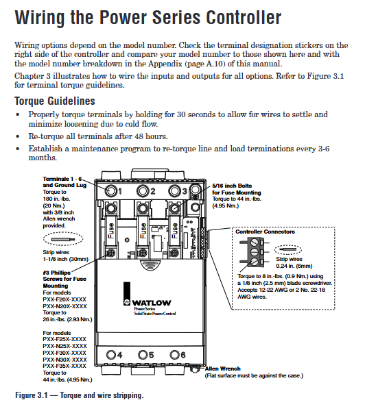
Installation tools: Phillips # 3 screwdriver, 3/8-inch hex wrench (terminal torque), torque wrench (180 in lbs range).
Essential accessories: semiconductor fuses (matched by model, such as 65A controller with 100A fuses), grounding wires (with the same specifications as power lines), shielding wires (for communication and signal retransmission).
(2) Detailed installation steps
1. Panel installation (N20-F30 model)
Process panel cuts according to dimensions of 55mm × 55mm (± 0.5mm), with a panel thickness of 1.5-9.7mm.
Fixed mounting plate: Use 4 # 10-1/4 inch screws (provided by the user) to secure the mounting plate to the panel with a torque of 8-10 in lbs.
Install controller: Align the positioning pin on the controller heat sink with the key slot on the mounting plate, push in and press down until the buckle is securely fastened, and confirm that there is no looseness.
- OMRON
- ABB
- General Electric
- EMERSON
- Honeywell
- HIMA
- ALSTOM
- Rolls-Royce
- MOTOROLA
- Rockwell
- Siemens
- Woodward
- YOKOGAWA
- FOXBORO
- KOLLMORGEN
- MOOG
- KB
- YAMAHA
- BENDER
- TEKTRONIX
- Westinghouse
- AMAT
- AB
- XYCOM
- Yaskawa
- B&R
- Schneider
- KONGSBERG
- NI
- WATLOW
- ProSoft
- SEW
- ADVANCED
- Reliance
- TRICONEX
- METSO
- MAN
- Advantest
- STUDER
- DANAHER MOTION
- Bently
- Galil
- EATON
- MOLEX
- DEIF
- B&W
- ZYGO
- Aerotech
- DANFOSS
- Beijer
- Moxa
- Rexroth
- Johnson
- WAGO
- TOSHIBA
- BMCM
- SMC
- HITACHI
- HIRSCHMANN
- Application field
- XP POWER
- CTI
- TRICON
- STOBER
- Thinklogical
- Horner Automation
- Meggitt
- Fanuc
- Baldor
- SHINKAWA
- Other Brands
- UniOP
- KUKA
- Iba
- Beckhoff
-
 Basler D90 96801 100 PCB Card
 -
 Basler XR2002F Voltage Regulator (110 VAC, 48-480 Hz)
 -
 Basler SR8A-2B14B3A Regulator
 -
 Basler 9561500100 Module
 -
 Basler DECS-400 BE1-11 System
 -
 Basler DECS-100-B15 Excitation Control
 -
 Basler SCP 210 Frequency Controller
 -
 Basler SR4A-2B15B3A Static Voltage Regulator
 -
 Basler BE1-32R Power Relay
 -
 Basler PIA2400-17GM Power Interface Adapter
 -
 Basler MVC 232 Manual Voltage Control Module
 -
 Basler SSR 32-12 Static Voltage Regulator
 -
 Basler 5MW AVR Generator Voltage Regulator
 -
 Basler VR63-4B Voltage Regulator
 -
 Basler DECS-100-A05 AVR for Engine Generator
 -
 Basler DECS-100-B15 Automatic Voltage Regulator
 -
 Basler BE1-32R Directional Power Relay
 -
 Basler BE1-87B Differential Relay
 -
 Basler UFOV 260A Protective Module
 -
 Basler 9-2614-02-100 PCB Rev M
 -
Basler DECS-100-B15 Digital AVR
-
 Basler 9284900103 PS DECS-400N
 -
 Basler D4N3H1U Intertie Protection
 -
 Basler DECS-100-B15 A15 AVR
 -
 Basler KR4F Voltage Regulator
 -
 Basler BE26434 T14 Transformer
 -
 Basler SR8A-2B15B3A Regulator
 -
 Westinghouse 774B472A12 AR Relay
 -
Basler DECS-100-B15 AVR
-
Basler XR2002F Regulator 110V
-
Basler SR125-E Static Regulator
-
 Basler SSR 125-12 Regulator
 -
 Basler MOC2599 Motor Pot
 -
 Basler BE1-DFPR Feeder Relay
 -
 Basler CBS 305 Current Boost
 -
 Basler BE1-25 AutoSync
 -
 Basler MVC 300 Voltage Control
 -
 Basler BE3-25A AutoSync
 -
 Basler KR7FF Static Regulator
 -
 Basler 90-49000-100 Regulator
 -
 Basler 880 kVA Dry Type Transformer Specs
 -
 Basler Electric BE1-25 Sync-Check Relay Specs
 -
 Basler SSR 125-12 Voltage Regulator Specs
 -
 Basler Electric BE1-851 Overcurrent Relay Review
 -
Basler Electric 149D930G02 Control Sub-Assembly
-
 Basler Electric BE1-81O/UT Frequency Relay Specs
 -
 Basler Electric BE1-51/27C Overcurrent Relay
 -
 Basler Electric 149D956G02 Industrial Component
 -
Basler Electric BE1-51A Overcurrent Relay Specs
-
 Basler Electric BE1-40Q Loss of Excitation Relay
 -
 Basler DECS-200 Excitation Control System
 -
 Basler DECS-200 Voltage Regulator 56-277V AC / 125V DC
 -
Basler BE1-87T Transformer Differential Relay
-
 Basler RDP-110-S1 Protection Relay
 -
 Basler BE1-700V Digital Protective Relay
 -
 Basler BE1-951 Overcurrent Protection System
 -
 Basler DECS-300 Digital Excitation Control
 -
 Basler DECS-200 Digital Excitation Control
 -
 Basler DECS-200-1C Excitation Control System
 -
Basler DECS-200-1L Digital Excitation Control
-
 Basler Electric BE1-GPS Generator Protection System
 -
Basler Electric DECS-200-1C Digital Excitation Controller
-
 Basler Electric DECS125-15 Excitation Control with Power Module
 -
 Basler Electric BE1-87G Differential Relay
 -
 Basler Electric BE1-11 Protection System I5A3M2P2N0EA00
 -
Basler Electric DECS-200-1C Excitation Control System
-
Basler Electric BE1-11g Generator Protection Relay
-
Basler Electric DECS 125-15-B2C1 V2.0.9 Excitation Control
-
 Basler Electric BE1-81O/UT3ED1JA7N2F Frequency Relay
 -
Basler Electric BE1-81O/UT3EE1YB7N1F Frequency Relay
-
 Basler Electric DECS-200-1L Digital Excitation Control System
 -
Basler DECS125-15-B2C1 Excitation Control
-
 Basler 9507900205 SSR Retrofit Voltage Regulator
 -
 Basler BE2000E Digital Voltage Regulator
 -
 Basler BE1-GPS Generator Protection System
 -
Basler DECS-250-CN1CN1N Digital Excitation Control
-
 Basler DGC-2020 Genset Controller
 -
 Basler BE1-81O UT3ED1LA7N0F Frequency Relay (Variant)
 -
 Basler BE1-81O UT3EE1YA9S0F Frequency Relay (Variant)
 -
Basler BE1-81O Over/Under Frequency Relay
-
Basler DECS125-15 Digital Excitation Control
-
Basler Electric BE1-951 Overcurrent Protection System
-
 Basler Electric BE1-700V Digital Protective Relay
 -
 Basler Electric APR63-5 Automatic Voltage Regulator
 -
Basler Electric BE1-851 Overcurrent Protection System
-
Basler Electric DECS-250-LN1SN1N Excitation Control
-
 Basler Electric BE1-87T Transformer Differential Relay
 -
Basler Electric DECS-200-1L Excitation Control System
-
 Basler Electric 9310300100 DECS-300 Excitation Control
 -
 Basler Electric SSE-N 125-4.5KW Shunt Exciter Regulator
 -
 Basler Electric DGC-2020HD-5NS1DNSBA Genset Controller
 -
Basler Electric BE1-81-O/UT3EE1JB7N1F Frequency Relay
-
Basler Electric BE1-81T1EE1WA0N1F Frequency Relay
-
 Basler Electric BE1-25M1EA6PN5R1F Sync-Check Relay
 -
 Basler Electric BE1-GPS Generator Protection System
 -
Basler Electric DECS-250-LN1SN1N Excitation Control Rev V
-
 Basler Electric DECS-250-CN2CN1N Excitation Control
 -
Basler Electric BE1-50/51B-207 Overcurrent Relay
-
Basler Electric DECS-300-C0N0 Excitation Control System
-
Basler Electric DECS-200 Digital Excitation Control System
-
Basler Electric DECS-250-LN1CN1N Excitation Unit
-
Basler Electric DECS-250 LN2SA1D Excitation Unit Specs
-
Basler Electric BE1-87T Transformer Relay Review
-
Basler Electric BE1-11 Protection System
-
Basler Electric BE1-GPS100-E4N1H1N Protection System
-
 Allen-Bradley 442G-MABH-R Safety Module
 -
 Beckhoff CX1030-0111 PLC Assembly Profile
 -
 FANUC IC693CPU364 PLC Module
 -
 Orange Denmark Type 200816 220 PLC Specs
 -
 OMRON C200H-SNT31 Sysmac PLC Module
 -
 Allen Bradley 20AB022A3AYNANC0 PowerFlex 70
 -
 OMRON C200HW-PCU01 Position Control Unit
 -
 ABB AO845A-eA Analog Output Module
 -
 OMRON CJ1M-CPU22 CPU Unit
 -
 Allen Bradley 100-E265ED11 Contactor
 -
 Honeywell 51304511-100 Interface Module
 -
 SOLEXY BXF3S0101N0018 Gateway Module
 -
 OMRON CJ2H-CPU65 CPU Unit
 -
 Automation Direct GS2-45P0 AC Drive
 -
 M68-2000 2-Axis Motion CNC Controller
 -
 OMRON CJ1M-CPU11 V3.0 PLC CPU Unit
 -
 OMRON CJ1W-NC413 4-Axis Positioning Controller
 -
 OMRON 3G2A3-PRO16 Programming Console HMI
 -
 Siemens 3VT8440-2AA04-2GA2 Molded Case Circuit Breaker
 -
 Siemens 3RT5045 Contactor Series
 -
 OMRON C200HS-CPU01-E SYSMAC PLC Controller
 -
 OMRON C500-NC103-E Positioning Control Unit
 -
 OMRON CJ1W-TC001 Temperature Control Unit


