
Watlow Power Series microprocessor based SCR power controller
2. Bolt fixation (F35 model)
Drill 6 1/4-20 threaded holes according to the drawing, with hole spacing as shown in Figure 2.2aa of the manual.
Use 6 1/4-20 bolts (to be provided by the user) to secure the controller to the mounting surface, with a torque of 18-20 in lbs, to ensure that the heat sink fits snugly onto the mounting surface.
(3) Wiring specifications and examples
1. Power and load wiring (key precautions)
Wire selection:
Material: Only copper wires are allowed, with an insulation level of 90 ° C (NEC standard).
Specification: Choose according to the current, such as 6 AWG for 65A and 250 MCM for 250A. Please refer to Table 6-79 in the manual for details.
Bending radius: The minimum bending radius is 2.0-8.5 inches (depending on the wire specifications) to avoid excessive bending and damage to insulation.
Terminal torque:
Main power/load terminal (1-6 and ground terminal): 180 in lbs (20 Nm), use a 3/8-inch hex wrench and hold for 30 seconds to ensure stable cold current of the wire.
Control signal terminal (10-23): 8 in lbs (0.9 Nm), using a 1/8 inch flathead screwdriver, wire stripping length 6mm (0.24 inches).
Installation of fuses:
Location: Fuse holder inside the controller (requires sliding the fuse cover to open), only use Watlow recommended models (such as 0808-0102 series) or equivalent Bussmann models (such as 170M1317).
Torque: The torque of the fuse bolt is 44 in lbs (4.95 Nm) to avoid poor contact and heat generation.
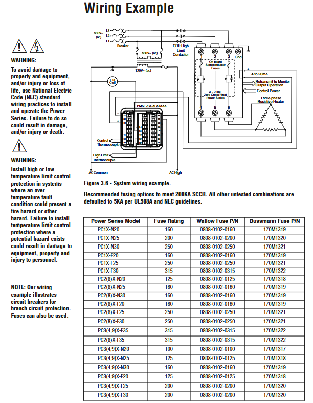
2. Typical wiring example (three-phase three bridge arm configuration)
Power input: L1/L2/L3 is connected to three-phase 480V AC, N is connected to the neutral line (if the load is grounded), and the grounding terminal is connected to the protective grounding (same specifications as the power line).
Load output: Connect U/V/W to a three-phase heater, ensuring that the load is grounded or delta connected, and the phase rotation is clockwise from A-B-C.
Control signal: 4-20mA input terminal 13 (+)/14 (-), common ground terminal 15.
Alarm output: Terminals 17 (NO)/18 (C)/19 (NC) are connected to external alarm lights or PLC inputs, with a rated current not exceeding 3A.
Communication: RS-485 terminal 21 (485 T/R+)/22 (485 T/R -)/23 (GND) is connected to the bus, and the shielding layer is only grounded at the controller end.
3. Anti interference wiring measures
Wiring separation: The distance between the input signal line (control/communication/retransmission) and the power line/load line should be ≥ 305mm (12 inches), and when crossing, it should be at a 90 ° angle to avoid parallel wiring.
Shielding treatment: Control signals and communication lines use shielded twisted pair cables, with the shielding layer grounded at one end (controller end) to avoid grounding loops.
Inductive load suppression: If the load contains inductive components such as contactor coils and solenoid valves, RC suppressors (such as Watlow 0804-0147-0000) need to be connected in parallel to reduce switch noise.
Operation and parameter configuration
(1) Operation interface and navigation
1. Button and display functions
Component Function Description Operation Example
The parameter values (such as input current and output power) are displayed on the upper screen, and the error code "20.0" indicates that the current output power is 20.0%
The lower display screen shows parameter names (such as [` In], [` Out]), and the menu hierarchy displays "[algo]", indicating that the current control algorithm menu is in progress
Adjust parameter values using the addition and subtraction keys (Ó/Î) (short press ± 1, long press to quickly increase or decrease), switch menus, and press the Ó key on the settings page to switch to the next menu
Left and right keys (¬/ ®) Switch parameters within the menu, confirm selection, and press in the [alpha] menu ® Switch to the [Off] parameter with the key
Home button (±) returns to display loop, switches area/phase. Press the ± button on the settings page to return to display loop and view real-time parameters
The alarm indicator light is red and lights up when an alarm is triggered. If the alarm is locked, it needs to be manually cleared. Flashing indicates that the alarm has not been confirmed, while constant light indicates that it has been confirmed
The communication indicator light is green, flashing indicates communication activity. No flashing indicates communication interruption, and the parameters need to be checked
2. Menu structure and navigation path
Display Loop: default page for monitoring real-time parameters, path: press the ± key to return from any menu.
Single phase equipment: displays [In] (input signal), [Out] (output power), [UoL] (line voltage), and [Cur] (load current).
Three phase equipment: Press the ± key to switch phases and display the voltage/current of each phase, such as [Uol1]/[Cur1] (L1 phase).
Setup Page: Configure control, alarm, and communication parameters. Path: Display loop. Press and hold the ±+¬ keys for 2 seconds, and the next screen will display "SEt".
Core menu: [alpha] (Control Algorithm), [Ctrl/2/3] (Area Control), [Opt1/2/3] (Area Options), ['arl] (Alarm), [Om] (Communication), [retry].
- OMRON
- ABB
- General Electric
- EMERSON
- Honeywell
- HIMA
- ALSTOM
- Rolls-Royce
- MOTOROLA
- Rockwell
- Siemens
- Woodward
- YOKOGAWA
- FOXBORO
- KOLLMORGEN
- MOOG
- KB
- YAMAHA
- BENDER
- TEKTRONIX
- Westinghouse
- AMAT
- AB
- XYCOM
- Yaskawa
- B&R
- Schneider
- KONGSBERG
- NI
- WATLOW
- ProSoft
- SEW
- ADVANCED
- Reliance
- TRICONEX
- METSO
- MAN
- Advantest
- STUDER
- DANAHER MOTION
- Bently
- Galil
- EATON
- MOLEX
- DEIF
- B&W
- ZYGO
- Aerotech
- DANFOSS
- Beijer
- Moxa
- Rexroth
- Johnson
- WAGO
- TOSHIBA
- BMCM
- SMC
- HITACHI
- HIRSCHMANN
- Application field
- XP POWER
- CTI
- TRICON
- STOBER
- Thinklogical
- Horner Automation
- Meggitt
- Fanuc
- Baldor
- SHINKAWA
- Other Brands
- UniOP
- KUKA
- Iba
- Beckhoff
-
 Basler D90 96801 100 PCB Card
 -
 Basler XR2002F Voltage Regulator (110 VAC, 48-480 Hz)
 -
 Basler SR8A-2B14B3A Regulator
 -
 Basler 9561500100 Module
 -
 Basler DECS-400 BE1-11 System
 -
 Basler DECS-100-B15 Excitation Control
 -
 Basler SCP 210 Frequency Controller
 -
 Basler SR4A-2B15B3A Static Voltage Regulator
 -
 Basler BE1-32R Power Relay
 -
 Basler PIA2400-17GM Power Interface Adapter
 -
 Basler MVC 232 Manual Voltage Control Module
 -
 Basler SSR 32-12 Static Voltage Regulator
 -
 Basler 5MW AVR Generator Voltage Regulator
 -
 Basler VR63-4B Voltage Regulator
 -
 Basler DECS-100-A05 AVR for Engine Generator
 -
 Basler DECS-100-B15 Automatic Voltage Regulator
 -
 Basler BE1-32R Directional Power Relay
 -
 Basler BE1-87B Differential Relay
 -
 Basler UFOV 260A Protective Module
 -
 Basler 9-2614-02-100 PCB Rev M
 -
Basler DECS-100-B15 Digital AVR
-
 Basler 9284900103 PS DECS-400N
 -
 Basler D4N3H1U Intertie Protection
 -
 Basler DECS-100-B15 A15 AVR
 -
 Basler KR4F Voltage Regulator
 -
 Basler BE26434 T14 Transformer
 -
 Basler SR8A-2B15B3A Regulator
 -
 Westinghouse 774B472A12 AR Relay
 -
Basler DECS-100-B15 AVR
-
Basler XR2002F Regulator 110V
-
Basler SR125-E Static Regulator
-
 Basler SSR 125-12 Regulator
 -
 Basler MOC2599 Motor Pot
 -
 Basler BE1-DFPR Feeder Relay
 -
 Basler CBS 305 Current Boost
 -
 Basler BE1-25 AutoSync
 -
 Basler MVC 300 Voltage Control
 -
 Basler BE3-25A AutoSync
 -
 Basler KR7FF Static Regulator
 -
 Basler 90-49000-100 Regulator
 -
 Basler 880 kVA Dry Type Transformer Specs
 -
 Basler Electric BE1-25 Sync-Check Relay Specs
 -
 Basler SSR 125-12 Voltage Regulator Specs
 -
 Basler Electric BE1-851 Overcurrent Relay Review
 -
Basler Electric 149D930G02 Control Sub-Assembly
-
 Basler Electric BE1-81O/UT Frequency Relay Specs
 -
 Basler Electric BE1-51/27C Overcurrent Relay
 -
 Basler Electric 149D956G02 Industrial Component
 -
Basler Electric BE1-51A Overcurrent Relay Specs
-
 Basler Electric BE1-40Q Loss of Excitation Relay
 -
 Basler DECS-200 Excitation Control System
 -
 Basler DECS-200 Voltage Regulator 56-277V AC / 125V DC
 -
Basler BE1-87T Transformer Differential Relay
-
 Basler RDP-110-S1 Protection Relay
 -
 Basler BE1-700V Digital Protective Relay
 -
 Basler BE1-951 Overcurrent Protection System
 -
 Basler DECS-300 Digital Excitation Control
 -
 Basler DECS-200 Digital Excitation Control
 -
 Basler DECS-200-1C Excitation Control System
 -
Basler DECS-200-1L Digital Excitation Control
-
 Basler Electric BE1-GPS Generator Protection System
 -
Basler Electric DECS-200-1C Digital Excitation Controller
-
 Basler Electric DECS125-15 Excitation Control with Power Module
 -
 Basler Electric BE1-87G Differential Relay
 -
 Basler Electric BE1-11 Protection System I5A3M2P2N0EA00
 -
Basler Electric DECS-200-1C Excitation Control System
-
Basler Electric BE1-11g Generator Protection Relay
-
Basler Electric DECS 125-15-B2C1 V2.0.9 Excitation Control
-
 Basler Electric BE1-81O/UT3ED1JA7N2F Frequency Relay
 -
Basler Electric BE1-81O/UT3EE1YB7N1F Frequency Relay
-
 Basler Electric DECS-200-1L Digital Excitation Control System
 -
Basler DECS125-15-B2C1 Excitation Control
-
 Basler 9507900205 SSR Retrofit Voltage Regulator
 -
 Basler BE2000E Digital Voltage Regulator
 -
 Basler BE1-GPS Generator Protection System
 -
Basler DECS-250-CN1CN1N Digital Excitation Control
-
 Basler DGC-2020 Genset Controller
 -
 Basler BE1-81O UT3ED1LA7N0F Frequency Relay (Variant)
 -
 Basler BE1-81O UT3EE1YA9S0F Frequency Relay (Variant)
 -
Basler BE1-81O Over/Under Frequency Relay
-
Basler DECS125-15 Digital Excitation Control
-
Basler Electric BE1-951 Overcurrent Protection System
-
 Basler Electric BE1-700V Digital Protective Relay
 -
 Basler Electric APR63-5 Automatic Voltage Regulator
 -
Basler Electric BE1-851 Overcurrent Protection System
-
Basler Electric DECS-250-LN1SN1N Excitation Control
-
 Basler Electric BE1-87T Transformer Differential Relay
 -
Basler Electric DECS-200-1L Excitation Control System
-
 Basler Electric 9310300100 DECS-300 Excitation Control
 -
 Basler Electric SSE-N 125-4.5KW Shunt Exciter Regulator
 -
 Basler Electric DGC-2020HD-5NS1DNSBA Genset Controller
 -
Basler Electric BE1-81-O/UT3EE1JB7N1F Frequency Relay
-
Basler Electric BE1-81T1EE1WA0N1F Frequency Relay
-
 Basler Electric BE1-25M1EA6PN5R1F Sync-Check Relay
 -
 Basler Electric BE1-GPS Generator Protection System
 -
Basler Electric DECS-250-LN1SN1N Excitation Control Rev V
-
 Basler Electric DECS-250-CN2CN1N Excitation Control
 -
Basler Electric BE1-50/51B-207 Overcurrent Relay
-
Basler Electric DECS-300-C0N0 Excitation Control System
-
Basler Electric DECS-200 Digital Excitation Control System
-
Basler Electric DECS-250-LN1CN1N Excitation Unit
-
Basler Electric DECS-250 LN2SA1D Excitation Unit Specs
-
Basler Electric BE1-87T Transformer Relay Review
-
Basler Electric BE1-11 Protection System
-
Basler Electric BE1-GPS100-E4N1H1N Protection System
-
 Allen-Bradley 442G-MABH-R Safety Module
 -
 Beckhoff CX1030-0111 PLC Assembly Profile
 -
 FANUC IC693CPU364 PLC Module
 -
 Orange Denmark Type 200816 220 PLC Specs
 -
 OMRON C200H-SNT31 Sysmac PLC Module
 -
 Allen Bradley 20AB022A3AYNANC0 PowerFlex 70
 -
 OMRON C200HW-PCU01 Position Control Unit
 -
 ABB AO845A-eA Analog Output Module
 -
 OMRON CJ1M-CPU22 CPU Unit
 -
 Allen Bradley 100-E265ED11 Contactor
 -
 Honeywell 51304511-100 Interface Module
 -
 SOLEXY BXF3S0101N0018 Gateway Module
 -
 OMRON CJ2H-CPU65 CPU Unit
 -
 Automation Direct GS2-45P0 AC Drive
 -
 M68-2000 2-Axis Motion CNC Controller
 -
 OMRON CJ1M-CPU11 V3.0 PLC CPU Unit
 -
 OMRON CJ1W-NC413 4-Axis Positioning Controller
 -
 OMRON 3G2A3-PRO16 Programming Console HMI
 -
 Siemens 3VT8440-2AA04-2GA2 Molded Case Circuit Breaker
 -
 Siemens 3RT5045 Contactor Series
 -
 OMRON C200HS-CPU01-E SYSMAC PLC Controller
 -
 OMRON C500-NC103-E Positioning Control Unit
 -
 OMRON CJ1W-TC001 Temperature Control Unit


