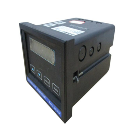
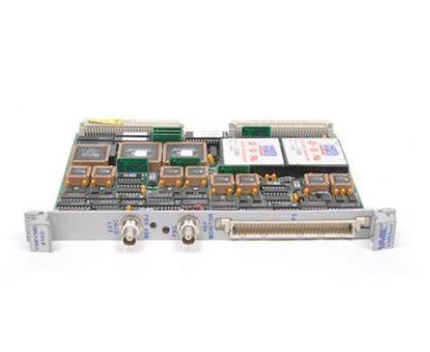
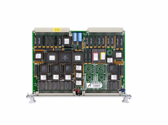
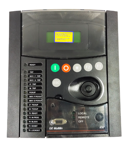
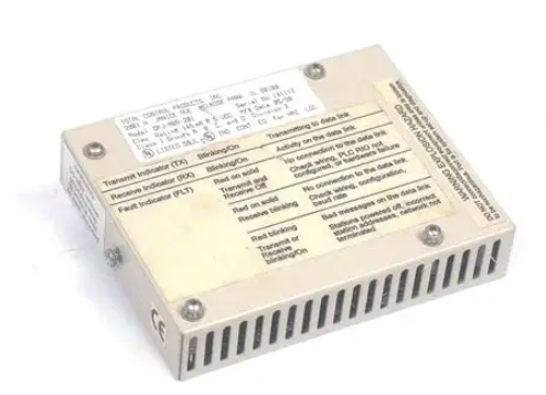
ABB REF54 series relay protection device
Configuration and operation points
1. Protection of fixed value configuration logic
The device supports configuring settings according to the "protection group" to meet different operating mode requirements (such as "normal operation", "maintenance mode", "backup power on/off"). The core configuration steps are as follows:
Enter the "Fixed Value Settings" menu (requires administrator privileges, password protection);
Select the type of protection object (such as "feeder protection" or "transformer protection"), and the system will automatically load the default protection logic template;
Adjust specific settings (such as overcurrent settings and action time limits), support real-time preview of the effective range of settings (to avoid exceeding the device's allowable values);
Save the set value and activate it (some models require restarting the device or manually switching the protection group), and automatically record the set value modification event after activation.
2. Installation and wiring specifications
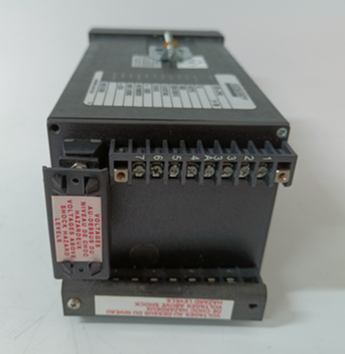
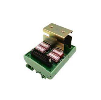
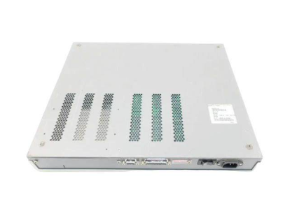
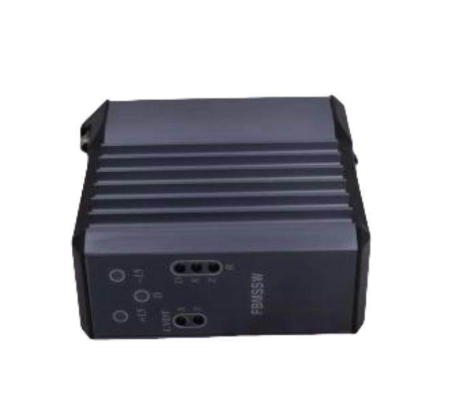
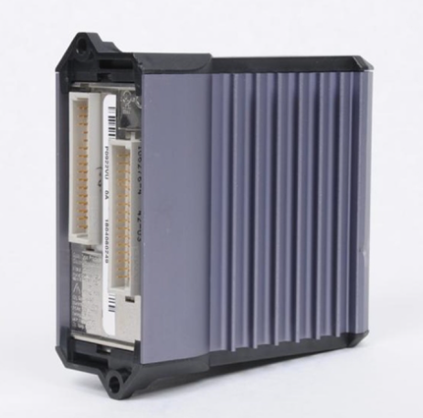
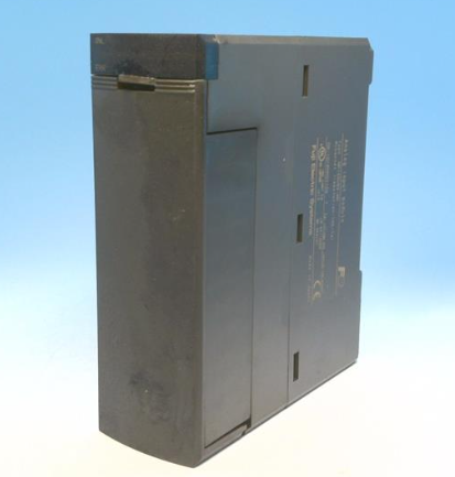
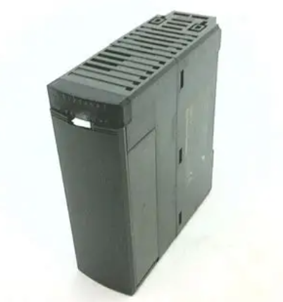
Installation method: Using standard DIN rail installation (35mm rail), compact size (width x height x depth about 90 x 140 x 180mm), suitable for installation inside 19 inch distribution cabinet doors or cabinets, with a reserved installation spacing of ≥ 50mm (for heat dissipation);
Wiring requirements:
Current circuit: Attention should be paid to the polarity of the CT secondary side wiring ("P1" in "P2" out) to avoid reverse connection and protection misoperation;
Voltage circuit: PT wiring needs to distinguish between line voltage (such as Uab, Ubc) and phase voltage (such as Ua, Ub, Uc) to ensure correct measurement and protection logic;
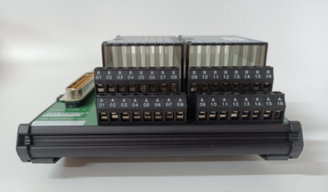
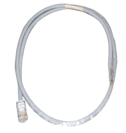
Communication circuit: RS485 uses shielded twisted pair cables (shielded layer single ended grounding), Ethernet uses CAT5e or above network cables, and the distance between strong current cables is ≥ 100mm to reduce interference.
Maintenance and troubleshooting
1. Regular maintenance plan
Daily inspection (daily/weekly): Check the LCD display screen to confirm that there are no fault alarms (such as "CT disconnection" or "PT voltage loss"); Check the status of the indicator lights (green power light on, flashing running light is normal);
Regular maintenance (monthly/quarterly): Clean the surface dust of the device (wipe with a dry dust-free cloth); Check the tightness of the wiring terminals (to avoid looseness and poor contact); Export event records and measurement data through the upper computer, analyze equipment operation trends;
Annual maintenance: Testing the accuracy of protection settings (using relay protection testers to simulate fault signals and verify the correctness of actions); Check the tripping outlet relay contacts (measure the continuity of the contacts with a multimeter); Upgrade device firmware (download the latest version from ABB's official website and upgrade via USB or Ethernet).
2. Common faults and solutions
Possible causes and solutions for the fault phenomenon
The power light is not on, the power supply is not powered, the power module is faulty, and the wiring is loose. Check the output of the 220V/110V DC power supply; Re plug and unplug the power supply wiring; Replace the power module
The protection device refuses to operate and the protection setting is incorrect, the CT/PT wiring is reversed, and the tripping circuit fault occurs. Re check the protection setting (such as whether the overcurrent setting is lower than the fault current); Check CT/PT polarity; Test the tripping outlet relay (simulate the tripping signal with a tester)
Communication interruption (with upper computer), communication line failure, IP address conflict, protocol mismatch, replacement of communication line; Reconfigure RS485 address/IP address (to avoid conflicts); Confirm that the communication protocol is consistent (such as Modbus RTU slave address)
Display the "CT disconnection" alarm for CT circuit open circuit, CT fault, and internal sampling circuit fault. Check the CT secondary side wiring (whether it is open circuit); Measure the CT circuit resistance with a multimeter (normally ≤ 5 Ω); Contact ABB for after-sales inspection of the sampling circuit of the device
- EMERSON
- Honeywell
- CTI
- Rolls-Royce
- General Electric
- Woodward
- Yaskawa
- xYCOM
- Motorola
- Siemens
- Rockwell
- ABB
- B&R
- HIMA
- Construction site
- electricity
- Automobile market
- PLC
- DCS
- Motor drivers
- VSD
- Implications
- cement
- CO2
- CEM
- methane
- Artificial intelligence
- Titanic
- Solar energy
- Hydrogen fuel cell
- Hydrogen and fuel cells
- Hydrogen and oxygen fuel cells
- tyre
- Chemical fiber
- dynamo
- corpuscle
- Pulp and paper
- printing
- fossil
- FANUC
- Food and beverage
- Life science
- Sewage treatment
- Personal care
- electricity
- boats
- infrastructure
- Automobile industry
- metallurgy
- Nuclear power generation
- Geothermal power generation
- Water and wastewater
- Infrastructure construction
- Mine hazard
- steel
- papermaking
- Natural gas industry
- Infrastructure construction
- Power and energy
- Rubber and plastic
- Renewable energy
- pharmacy
- mining
- Plastic industry
- Schneider
- Kongsberg
- NI
- Wind energy
- International petroleum
- International new energy network
- gas
- WATLOW
- ProSoft
- SEW
- wind
- ADVANCED
- Reliance
- YOKOGAWA
- TRICONEX
- FOXBORO
- METSO
- MAN
- Advantest
- ADVANCED
- ALSTOM
- Control Wave
- AB
- AMAT
- STUDER
- KONGSBERG
- MOTOROLA
- DANAHER MOTION
- Bently
- Galil
- EATON
- MOLEX
- Triconex
- DEIF
- B&W
- ZYGO
- Aerotech
- DANFOSS
- KOLLMORGEN
- Beijer
- Endress+Hauser
- MOOG
- KB
- Moxa
- Rexroth
- YAMAHA
- Johnson
- Westinghouse
- WAGO
- TOSHIBA
- TEKTRONIX


Email:wang@kongjiangauto.com

