
ABB REF54 series relay protection device
ABB REF54 series relay protection device
This document is a technical document released by ABB for the REF54 series relay protection devices (presumably protection devices for medium and low voltage distribution systems, such as REF541, REF542, etc.). The core revolves around the functional characteristics, technical specifications, configuration logic, and application scenarios of the devices, aiming to guide electrical engineers in selecting devices, setting parameters, installing, debugging, and operating to ensure reliable protection of transformers, busbars, feeders, and other equipment in distribution networks (such as industrial plants, commercial buildings, and power distribution stations), in compliance with international relay protection standards such as IEC 60255.
Product core positioning and applicable scenarios
1. Core functional positioning
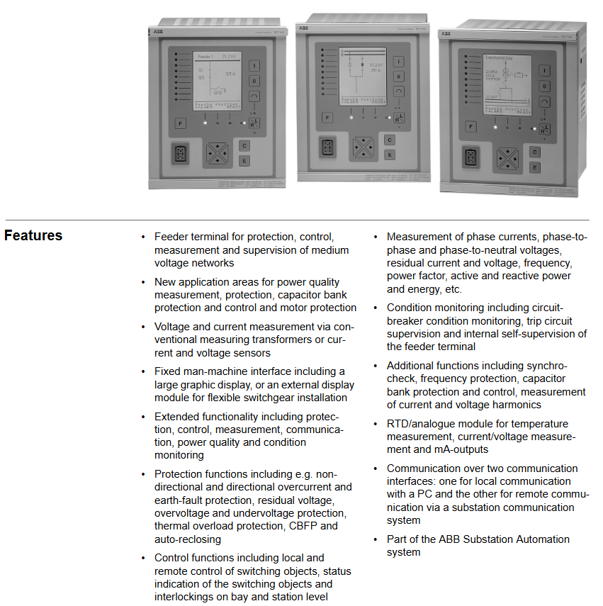
The REF54 series is a multifunctional digital relay protection device launched by ABB, integrating the four core functions of "protection, control, measurement, and communication". It can replace traditional discrete protection relays and measurement instruments, achieve comprehensive monitoring and rapid response to faults of distribution equipment, and cover specific functions:
Protection function: Provides overcurrent protection (inverse time limit/definite time limit), overload protection, ground fault protection, short circuit protection, undervoltage/overvoltage protection, etc. for different protected objects (transformers, feeders, busbars), supports protection setting grading (adapted to different operating conditions).
Control function: Supports local/remote operation (such as circuit breaker opening and closing, constant value switching), has operation locking logic (to prevent misoperation), and can be connected to external control signals (such as PLC, SCADA system instructions).
Measurement function: Real time collection of electrical parameters, including three-phase current, voltage, power (active/reactive), power factor, and electrical energy (cumulative/instantaneous), with a measurement accuracy of 0.2 level (compliant with IEC 60688 standard).
Event recording: Automatically record fault events (fault type, occurrence time, fault time parameters), operation records (opening and closing operations, constant value modification), storage capacity supports ≥ 1000 events, facilitating fault traceability and operation and maintenance analysis.
2. Typical Applicable Scenarios
Industrial power distribution: used for the protection of factory workshop power distribution circuits and motor control circuits, adapted to high load, multi start stop industrial environments, and supporting linkage with ABB AC500 and other PLC systems;
Commercial and civil buildings: As feeder protection devices for office buildings and residential distribution stations, they achieve overload and short circuit protection for lighting, air conditioning, and other loads;
Power distribution network: used for low-voltage protection of transformers in 10kV/0.4kV distribution stations, in conjunction with ABB SCADA system to achieve remote monitoring and unmanned operation.
Key technical specifications and performance parameters
1. Electrical and protective characteristics
Category core specifications (general reference, specific models may vary slightly)
Input parameter current input: 5A/1A (standard CT secondary current); Voltage input: 100V/220V (PT secondary voltage, line voltage/phase voltage optional); Frequency: 50/60Hz (automatic recognition)
Protection range for overcurrent protection: 0.1-10Ie (Ie is the rated current); Overload protection: 0.5-1.5Ie; Ground fault protection: 0.05-5Ie; Action time limit: 0.01-300s
Measurement accuracy current/voltage: ± 0.2%; Power/electric energy: ± 0.5%; Frequency: ± 0.01Hz
Trip outlet 2-4 sets of normally open/normally closed relay contacts (rated load: 5A@250VAC /30VDC), Support self checking of trip circuit (to avoid contact adhesion causing misoperation)
2. Communication and interface characteristics
Communication interface: Standard configuration includes 1 RS485 (supporting Modbus RTU protocol), optional 1 Ethernet (Ethernet/IP or Modbus TCP), supporting interconnection with upper computer (such as ABB MicroSCADA system), HMI or third-party control system to achieve data upload and remote control;
Local interface: Equipped with an LCD display screen (128 × 64 pixels, supporting Chinese/English display), 4 operation buttons (for setting settings and event queries), and some models come with a USB interface (for data export and firmware upgrade).
3. Environmental and compliance characteristics
Environmental adaptability: working temperature -25~+70 ℃ (wide temperature design), storage temperature -40~+85 ℃; Relative humidity ranging from 5% to 95% (without condensation); Anti vibration level 5g (10-500Hz, compliant with IEC 60068-2-6), suitable for complex environments inside distribution cabinets;
Compliance certification: Complies with IEC 60255 (General Standard for Relay Protection Devices), IEC 61000-6-2 (Electromagnetic Immunity for Industrial Environments), CE certification, UL 508 certification, and some models have passed ATEX Zone 2 explosion-proof certification (applicable to distribution in hazardous areas).
Configuration and operation points
1. Protection of fixed value configuration logic
The device supports configuring settings according to the "protection group" to meet different operating mode requirements (such as "normal operation", "maintenance mode", "backup power on/off"). The core configuration steps are as follows:
Enter the "Fixed Value Settings" menu (requires administrator privileges, password protection);
Select the type of protection object (such as "feeder protection" or "transformer protection"), and the system will automatically load the default protection logic template;
Adjust specific settings (such as overcurrent settings and action time limits), support real-time preview of the effective range of settings (to avoid exceeding the device's allowable values);
Save the set value and activate it (some models require restarting the device or manually switching the protection group), and automatically record the set value modification event after activation.
2. Installation and wiring specifications
Installation method: Using standard DIN rail installation (35mm rail), compact size (width x height x depth about 90 x 140 x 180mm), suitable for installation inside 19 inch distribution cabinet doors or cabinets, with a reserved installation spacing of ≥ 50mm (for heat dissipation);
Wiring requirements:
Current circuit: Attention should be paid to the polarity of the CT secondary side wiring ("P1" in "P2" out) to avoid reverse connection and protection misoperation;
Voltage circuit: PT wiring needs to distinguish between line voltage (such as Uab, Ubc) and phase voltage (such as Ua, Ub, Uc) to ensure correct measurement and protection logic;
Communication circuit: RS485 uses shielded twisted pair cables (shielded layer single ended grounding), Ethernet uses CAT5e or above network cables, and the distance between strong current cables is ≥ 100mm to reduce interference.
Maintenance and troubleshooting
1. Regular maintenance plan
Daily inspection (daily/weekly): Check the LCD display screen to confirm that there are no fault alarms (such as "CT disconnection" or "PT voltage loss"); Check the status of the indicator lights (green power light on, flashing running light is normal);
Regular maintenance (monthly/quarterly): Clean the surface dust of the device (wipe with a dry dust-free cloth); Check the tightness of the wiring terminals (to avoid looseness and poor contact); Export event records and measurement data through the upper computer, analyze equipment operation trends;
Annual maintenance: Testing the accuracy of protection settings (using relay protection testers to simulate fault signals and verify the correctness of actions); Check the tripping outlet relay contacts (measure the continuity of the contacts with a multimeter); Upgrade device firmware (download the latest version from ABB's official website and upgrade via USB or Ethernet).
2. Common faults and solutions
Possible causes and solutions for the fault phenomenon
The power light is not on, the power supply is not powered, the power module is faulty, and the wiring is loose. Check the output of the 220V/110V DC power supply; Re plug and unplug the power supply wiring; Replace the power module
The protection device refuses to operate and the protection setting is incorrect, the CT/PT wiring is reversed, and the tripping circuit fault occurs. Re check the protection setting (such as whether the overcurrent setting is lower than the fault current); Check CT/PT polarity; Test the tripping outlet relay (simulate the tripping signal with a tester)
Communication interruption (with upper computer), communication line failure, IP address conflict, protocol mismatch, replacement of communication line; Reconfigure RS485 address/IP address (to avoid conflicts); Confirm that the communication protocol is consistent (such as Modbus RTU slave address)
Display the "CT disconnection" alarm for CT circuit open circuit, CT fault, and internal sampling circuit fault. Check the CT secondary side wiring (whether it is open circuit); Measure the CT circuit resistance with a multimeter (normally ≤ 5 Ω); Contact ABB for after-sales inspection of the sampling circuit of the device

- OMRON
- ABB
- General Electric
- EMERSON
- Honeywell
- HIMA
- ALSTOM
- Rolls-Royce
- MOTOROLA
- Rockwell
- Siemens
- Woodward
- YOKOGAWA
- FOXBORO
- KOLLMORGEN
- MOOG
- KB
- YAMAHA
- BENDER
- TEKTRONIX
- Westinghouse
- AMAT
- AB
- XYCOM
- Yaskawa
- B&R
- Schneider
- KONGSBERG
- NI
- WATLOW
- ProSoft
- SEW
- ADVANCED
- Reliance
- TRICONEX
- METSO
- MAN
- Advantest
- STUDER
- DANAHER MOTION
- Bently
- Galil
- EATON
- MOLEX
- DEIF
- B&W
- ZYGO
- Aerotech
- DANFOSS
- Beijer
- Moxa
- Rexroth
- Johnson
- WAGO
- TOSHIBA
- BMCM
- SMC
- HITACHI
- HIRSCHMANN
- Application field
- XP POWER
- CTI
- TRICON
- STOBER
- Thinklogical
- Horner Automation
- Meggitt
- Fanuc
- Baldor
- SHINKAWA
- Other Brands
- UniOP
- KUKA
- Iba
- Beckhoff
- ADLINK
-
 GE Fanuc VMIVME-5588 High-speed Reflective Memory Board
 -
 VMIC VMIVME-5565 Reflective Memory Board
 -
 VMIC VMIVME-2127 Voltage Source Digital Output Board
 -
 VMIC VMIVME 4512 Analog VME Process PCB Assembly
 -
 GE Fanuc VMIVME-3122-022 Analog I/O Module
 -
 VMIC VMIVME 5576 High Speed Fiberoptic Network Board
 -
 FANUC VMIVME-7452 VMEbus Analog I/O Board
 -
 FANUC VMIVME-2210 VMEbus Digital Output Board
 -
 FANUC VMIVME-7750-734000 VMEbus Single Board Computer
 -
 VMIC VMIVME 2210 VMEbus DO 28V Digital Output Board
 -
 VMIC VMIVME DR11W VMEbus DMA Interface Module
 -
 VMIC VMIVME-2536-200 5V Optically Coupled Digital I/O Board
 -
 VMIC VME-7754 VMIVMF7754-259000 VMEbus Control Card
 -
 VMIC 2170A VME Interface Board
 -
 GE VMIC PMC-5565PIORC-210000 Reflective Memory PMC Node Card
 -
 VMIC VMIVME-7750-750000 VME Single Board Computer
 -
 VMIC VMIVME-7751 VME Single Board Computer
 -
 VMIC 332-004512 Analog VME Process Board
 -
 VMIC VMIVME2528 VME Interface Board
 -
FANUC VMIVME-2120 VME Bus Interface Board
-
 FANUC VMIVME-2540 VME Bus Interface Board
 -
 FANUC VMIVME-3230 VME Bus Interface Board
 -
 FANUC VMIVME-4514 VME Bus Interface Board
 -
 ETEL DSB2S154-211E-000H Servo Amplifier
 -
 ETEL DSCQT112-111-000 Motion Control Module
 -
 ETEL LMG20-050-3QB-211A Servo Motor – High Torque Linear
 -
 ETEL EU-LCP-0-0-1000-01 Communication Card
 -
 ETEL DSA2P174ZA-033A Servo Amplifier Driver
 -
 ETEL EA-P2M-400-15/40A-0100-00 Servo Driver
 -
 ETEL DSC2P152-111-000 Servo Drive Amplifier
 -
 ETEL LMS15-050-3UA-209A Linear Motor
 -
ETEL DSC2P152-111D-000A Controller
-
 ETEL DSB2P131-111E-000B Digital Servo Amplifier Position Controller
 -
 ETEL DSO-PWR111C-000B Power Supply Module
 -
 ETEL DSCDP324-321F-000C Servo Driver
 -
 ETEL DSC2P152-111B-000D Controller
 -
 ETEL DSB2P142-111E-000H Circuit Board
 -
 ETEL LMG05-030-3QA-H01 Linear Motor
 -
 ETEL DSC2P152-111F-000A Controller
 -
 ETEL DSA2S211ZA Servo Drive
 -
 ETEL DSCDM332-112-000 Drive Module
 -
 ETEL DSCDP334-421-000 Digital Position Controller Servo Drive
 -
ETEL EA-P2M-400-15/40A-0100-00 AccurET Servo Drive
-
 ETEL TMA0140-050-3UB-202B Torque Motor
 -
 ETEL DSA1DL1D.PCB Servo Drive Board
 -
 ETEL DSA2DL 1A Servo Drive
 -
 ETEL DSMAX111B-000B Servo Drive
 -
ETEL DSO-PWS111C-000B Power Supply Module
-
 ETEL DSC2P142-111B-000D Servo Drive Amplifier
 -
 ETEL DSC2P132-111D-000A Servo Drive Amplifier
 -
ETEL DSC2P152-111B-000D Servo Drive Amplifier
-
ETEL DSB2P131-121E-000H Servo Drive Amplifier
-
 ETEL DSB2P142-111E-000H Servo Drive Amplifier
 -
ETEL DSO-PWR112C-000A Power Supply Module – High Power
-
ETEL DSO-PWR111C-000A Power Supply Module
-
ETEL DSB2P121-121E-000H Servo Drive Amplifier
-
 ETEL DSB2S134-111E-000H Digital Servo Amplifier
 -
 ETEL RTMA0140-070-AQN-21E Motor
 -
ETEL DSCDP132-111-000 Dual Controller Circuit Board – Motion Control
-
 ETEL LMS15-050-3UA-209Aft Linear Motor
 -
 ETEL DSCDP324-322G-000A Position Controller
 -
ETEL DSA2P174ZA-033A Servo Amplifier Driver
-
 ETEL DSA2P174ZA-017A Servo Amplifier Driver
 -
 ETEL LMD10-050-3QA-223A Linear Motor
 -
ETEL EU-LGP-0-0-1000-00 PCI Network Card
-
ETEL DSO-PWS111C-000B Power Supply Module
-
ETEL DSC2V174-111C-001A Servo Controller
-
 ETEL EA-P2M-600-15/40A-0000-01 AccurET Modular Position Controller
 -
 ETEL RTMA0140-070-AQN-21B DD Motor
 -
 ETEL DSC2P144-421-000 Servo Driver
 -
ETEL EA-P2M-400-15-40A-0100-00 Servo Drive
-
ETEL DSCDM341-111C-000B Board
-
 ETEL LMD10-050-3QA-223A Motor
 -
ETEL RTMA0140-070-AQN-21E DD Motor
-
 ETEL DSCDM342-111-000 Servo Variator
 -
ETEL DSC2P152-111E-000A Servo Amplifier
-
ETEL LMS15-050-3UA-209A Motor
-
ETEL RTMA0140-070-AQN-21C DD Motor – High Torque Direct Drive
-
 ETEL DSCDP334-421G-000A Servo Drive
 -
Etel DSB2S154-211E-000H Digital Servo Amplifier
-
 ETEL EA-P2M-400-15/40A-0100-00 AccurET Servo Drive
 -
 ETEL DSA2P-174ZA-017A Digital Servo Amplifier
 -
ETEL EA-P2M-400-15/40A-0100-00 Servo Drive
-
ETEL LMP07-100-3TAS-229 Linear Motor Primary Part
-
ETEL LMA11-120-3ZA-359A Linear Motor
-
 ETEL EA-S0M-400-40/80A-0000-00 Drive Power Supply
 -
Etel DSCDP334-421-000 Driver
-
ETEL DSCDM341-111C-000B DSCDM Drive Board
-
Etel DSA1 Digital Servo Amplifier
-
ETEL DSA2P174ZA-033A Servo Amplifier
-
ETEL DSCDM342-111-000 Servo Verifier
-
 ETEL LMS15-050-3UA-209A Linear Motor
 -
ETEL P2M-048-2.5/5A AccurET Position Controller – Modular
-
ETEL LMD10-050-3QA-223A Linear Motor – Compact Precision
-
 ETEL EA-P2M-400-05/10A-0000-01 Drive – Precision Motion
 -
ETEL LMP07-100-3TAS-229 Linear Motor Primary Part
-
 ETEL EU-LGP-0-0-0000-00 Motion Control Card – Precision Control
 -
 ETEL DSC2P152-111E-000A Servo Amplifier
 -
ETEL EA-P2M-400-15/40A-0100-01 Servo Drive
-
 ETEL EA-SOM-300-40/80A-0000-00 AccurET Power Supply Module
 -
ETEL LMG10-1050-3QA-H01 Linear Motor
-
 ETEL EA-SOM-300-40/80A-0000-00 AccurET Modular Power Supply
 -
ETEL EA-P2M-400-15/40A-0100-00 AccurET Servo Drive
-
 ETEL EA-P2M-400-15/40A-0100-01 Servo Driver
 -
Etel RTMA0140-070-AQN-21B High Speed Motor
-
ETEL DSC2P141-111-000 Linear Servo Amplifier
-
ETEL DSB2S134-211E-000H Digital Servo Amplifier
-
ETEL 3LM-23C Motion Controller
-
Etel DSO-SER211-000 Power Add-On Board
-
ETEL DSCDP334-421-000 Servo Drive
-
 CTI-Cryogenics 8116071G001 Enhanced On-Board 8F Cryopump
 -
ETEL LMD10-050-3QA-223A Linear Motor
-
Etel DSO-SER211-000 Servo Card Power Add-On
-
ETEL LMG05-050-3QA-213A Linear Motor
-
Etel DSO-SER211-000 Power Add-On Board
-
ETEL EU-LGP-0-0-0000-00 Motion Control Card
-
ETEL EA-P2M-400-15/40A-0100-00 AccurET Servo Drive
-
 ETEL DSA2P1540A Digital Servo Amplifier
 -
ETEL DSC2P131-111-000 Drive Board
-
ETEL DSC2P131-111D-000A Servo Drive
-
Etel SA-IL 03-208 Linear Motor Section 208mm
-
 ETEL EA-P2M-300-4/7.5A-0000-01 AccurET Position Controller
 -
ETEL DSO-SER211-000 Power Board
-
ETEL DSC2P131-111F-000A Servo Amplifier
-
ETEL DSA1P6242B Digital Servo Amplifier
-
ETEL DSC2P131-111B-000B Regulator
-
ETEL DSA2P1540A Digital Servo Amplifier
-
ETEL EA-P2M-048-2.5/5A-0100-01 Drive


