
SERVOSTAR ® Usage of CD-LITE servo amplifier
SERVOSTAR ® CD-LITE servo amplifier
Basic information of the document
Product positioning: SERVOSTAR ® CD-LITE is an economical digital servo amplifier launched by Danaher Motion Kollmorgen. It focuses on current loop applications, supports full digital current and speed loop control, does not require potentiometer adjustment, and has digital parameter storage without drift. It is compatible with various brushless motors.
Version compatibility: The document has been revised to version 2 of 2003, corresponding to firmware version 1.1.0, and needs to be paired with MOTIONLINK 4.4.3 software (the two must match the version and cannot be mixed); Historical versions include version 1 from 2001 (firmware 0.1.2).
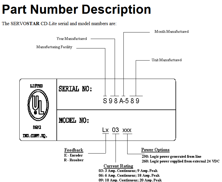
Core identification: The product model includes current level (03=3A continuous/9A peak, 06=6A continuous/18A peak, 09=10A continuous/20A peak), logic power mode (250=line generation, 260=external 24V power supply), and feedback type (E=encoder, R=rotary transformer, rotary transformer only supports external 24V logic power supply).
Product Core Features
(1) Basic functions
Control mode: Supports speed loop (OPMODE=1, ± 10V analog given), torque/current loop (OPMODE=3, ± 10V analog given), PWM switching frequency up to 16kHz.
Feedback support: Incremental encoder (A/B/Z+Hall, A/B+Hall), rotary transformer (requires external 24V logic power supply), Hall only (sine commutation/six step commutation), supports encoder equivalent output (EEO, orthogonal signal, up to 3MHz).
Power and protection: continuous current 3/6/10A, peak current is 3 times the continuous value; Equipped with overvoltage, undervoltage, overcurrent, overtemperature (driver/motor), feedback disconnection, and I ² t turn back protection (to prevent driver overheating).
(2) Hardware and Design
Isolation design: Electronic components are fully isolated, and the logic power supply can be generated by circuit or external 24V power supply, with strong anti-interference ability.
Communication interface: Only supports RS-232 serial port (for PC debugging or Personality Module configuration), baud rate 9600/19200bps (set by DIP switch 6), no extended communication interface (different from the full version SERVOSTAR CD).
I/O configuration: C3 interface includes differential analog input (ANIN1, 12 bit AD, 250 μ s/62.5 μ s sampling rate), remote enable input (REMOTE, 12-24V optocoupler isolation), fault relay output (RELAY, configurable "driver ready"/"driver enable" mode), 2 hardware limit switch inputs (only available for speed loop), and 1 analog output (ANOUT, 8-bit, monitoring speed/current/speed error/current command).
System startup and debugging
(1) Hardware and software requirements
PC configuration: IBM compatible (Pentium and above), 16MB memory, Windows 95/98/NT 4.0 (SP3)/2000, CD-ROM drive, 1 serial port (COM1-COM4).
Software installation: Automatically run (or manually execute "D: AUTORUN. EXE") through the MOTIONLINK installation disc, with the program path being "Start - Programs - SERVOSTAR MOTIONLINK".
(2) Debugging process
Communication settings: The RS-232 protocol has 8 data bits, 1 stop bit, no checksum, and the baud rate matches the DIP switch settings; The parameters are stored in EEPROM (non-volatile), and after modification, the "SAVE" command must be executed to save them to EEPROM, otherwise they will be lost due to power failure.
Quick Startup Wizard:
Driver configuration: Select bus voltage (VBUS) and monitor DIP switch status in real-time (address, baud rate, etc.);
Motor configuration: Select the model (such as GOLDLINE XT series) from the MOTIONLINK motor database, click "To Drive" to download parameters, and contact the manufacturer for unknown motors;
Mode configuration: Select control mode (speed/torque), torque mode does not require tuning, speed mode requires adjustment of PDFF parameters (VF/VD/COMPFILT);
Backup and Startup: Parameters can be saved as SSV file (for multi drive configuration), enter the main interface after completion.
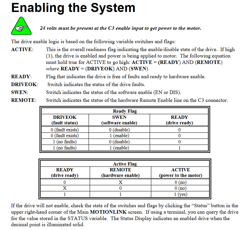
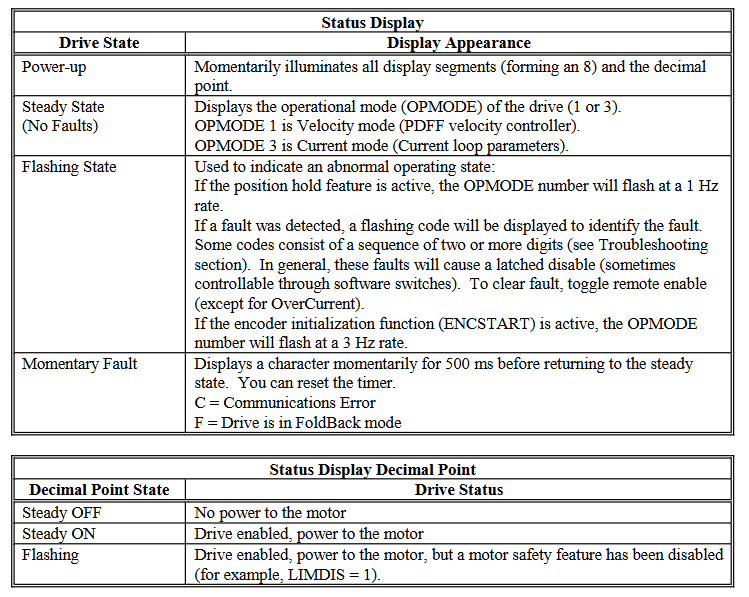
Driver Enable: Must meet the requirement of "ACTION=READY × REMOTE", where "READY=DRIVE OK × SWEN" (DRIVE OK=no fault, SWEN=software enable, REMOTE=hardware enable), and the decimal point in the status bar should remain lit after enabling.
Feedback system and control loop
(1) Feedback type details
Key parameter limitations and characteristics of feedback types
Incremental encoder resolution MENCRES (number of lines), can be scaled by ENCOUTO (1/2/4/8/16 times), cable length ≤ 15m, maximum input frequency 3MHz (before orthogonal)/12MHz (after orthogonal), supports wire breakage detection
The fixed resolution of the rotary transformer is 4096, and the RDRES automatically adjusts with speed (such as RDRES=1665536 counts/revolution when VLIM<1500RPM). The cable length is ≤ 22.9m (recommended shielded twisted pair), and the accuracy is composed of R/D converter (4 arcminutes), mechanical installation (8 arcminutes), etc. The total error is ≤ 19 arcminutes
Only Hall sine commutation (MENCTYPE=5) or six step commutation (DIP switch 2 set to ON, MENCTYPE=10) relies on Hall signals to generate commutation waveforms, which are updated once per Hall switch, with low accuracy and suitable for simple scenarios
(2) Control loop principle
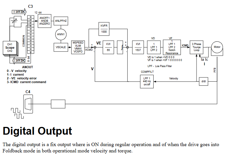
Current loop: fully digital pole configuration, sampling rate of 16kHz (62.5 μ s), converts current command into three-phase PWM signal, includes adaptive gain compensation for nonlinearity, monitors A/C phase current (IA/IC) and calculates equivalent current (I).
Reversing loop: With a frequency update of 16kHz, it converts single-phase signals into three-phase position modulated sine waves and supports the patented technology of "torque angle lead". It needs to be aligned with the back electromotive force of the motor (feedback alignment is crucial).
Speed loop: Sampling rate 4kHz, using PDFF (pseudo differential feedforward) algorithm, calculating actual speed through feedback, filtering the difference between the actual speed and the instruction speed, and sending it to the commutation loop, suitable for high-precision speed control.
Fault handling and maintenance
(1) Fault classification and troubleshooting
Fatal malfunction (driver disabled, some require power-off reset):
Overheating (t): Overload, fan failure, or power level damage, reset after cooling;
Overvoltage (o): During the regeneration process, the bus voltage is too high. Check the braking resistance or deceleration curve;
Overcurrent (P): Power level surge current, requiring power-off reset, checking for motor short circuit or power level fault;
Feedback fault (r1/r2/r4/r6): Rotary transformer/encoder disconnected or illegal Hall combination, check the feedback cable.
Non fatal fault (disabled drive, can be reset by enabling):
Undervoltage (u): Input voltage too low or power failure, check power supply;
Motor overheating (H): The motor thermostat detects overheating (PTC>12.4k Ω or NTC<0.5k Ω) and needs to cool down before resetting;
Overspeed (J/J1): If the speed exceeds VOSPD (or 1.8 × VLIM), check the speed setting or tuning parameters.
No message fault (only displayed in the status bar):
Limit switch (L1/L2/L3): Hardware limit trigger (CW/CCW switch open circuit), check the limit wiring;
Watchdog (≡): Software malfunction, need to contact the manufacturer;
RAM/EPROM malfunction (I/c): Memory test failed, hardware replacement is required.
(2) Firmware upgrade
Preparation files: The upgrade includes firmware (Lccd_ xxx. emb), Windows tools (Cdlignit. exe), and DOS tools (Ignite. exe).
Steps:
Turn off the power and set DIP switch 8/10 to 1;
Power on and confirm that the status bar displays "E" (entering Ember mode);
Run Cdlignit.exe, select the serial port and baud rate (default 115200), load the firmware file and start downloading;
After successful download, power off and restore DIP switch. After powering on, verify the version through the "VER" command.
Extended Configuration and Appendix
(1) Personality Module
Function: Quickly copy drive parameters, configure one and upload it to the module, then download it to other drives, including All parameters of the SSV file and the CONFIG/SAVE command.
Operation:
Upload: Insert the module into port C1, press and hold the hide switch for 2 seconds, and the status bar will flash with three bars: bottom, middle, and top;
Download: Press the explicit switch, and the status bar will flash up, middle, and down bars;
Fault: Upload error shows "-6", download error shows "-7", module or wiring needs to be checked.
(2) Appendix Key Information
Wiring diagram: Appendix A provides the pin correspondence of motor power supply (such as GOLDLINE B/M/EB/XT series), rotary transformer (LR), and encoder (LE), including line color labeling (such as motor MA corresponding to GOLDLINE B series PinA, brown wire).
Linear motor configuration: Appendix C provides the formula for converting linear parameters to rotational parameters (such as MSPEED=Vmaxl × 60/pole pitch, unit RPM), and the driver parameters need to be calculated based on the motor pole pitch, maximum linear velocity, etc.
Motor Thermostat: Appendix D supports PTC (THERMOTYPE=0) and NTC (THERMOTYPE=1), monitored through pin 13/25 of the C2 interface, triggering an "H" fault when overheated.
- OMRON
- ABB
- General Electric
- EMERSON
- Honeywell
- HIMA
- ALSTOM
- Rolls-Royce
- MOTOROLA
- Rockwell
- Siemens
- Woodward
- YOKOGAWA
- FOXBORO
- KOLLMORGEN
- MOOG
- KB
- YAMAHA
- BENDER
- TEKTRONIX
- Westinghouse
- AMAT
- AB
- XYCOM
- Yaskawa
- B&R
- Schneider
- KONGSBERG
- NI
- WATLOW
- ProSoft
- SEW
- ADVANCED
- Reliance
- TRICONEX
- METSO
- MAN
- Advantest
- STUDER
- DANAHER MOTION
- Bently
- Galil
- EATON
- MOLEX
- DEIF
- B&W
- ZYGO
- Aerotech
- DANFOSS
- Beijer
- Moxa
- Rexroth
- Johnson
- WAGO
- TOSHIBA
- BMCM
- SMC
- HITACHI
- HIRSCHMANN
- Application field
- XP POWER
- CTI
- TRICON
- STOBER
- Thinklogical
- Horner Automation
- Meggitt
- Fanuc
- Baldor
- SHINKAWA
- Other Brands
- UniOP
- KUKA
- Iba
- Beckhoff
-
 Basler D90 96801 100 PCB Card
 -
 Basler XR2002F Voltage Regulator (110 VAC, 48-480 Hz)
 -
 Basler SR8A-2B14B3A Regulator
 -
 Basler 9561500100 Module
 -
 Basler DECS-400 BE1-11 System
 -
 Basler DECS-100-B15 Excitation Control
 -
 Basler SCP 210 Frequency Controller
 -
 Basler SR4A-2B15B3A Static Voltage Regulator
 -
 Basler BE1-32R Power Relay
 -
 Basler PIA2400-17GM Power Interface Adapter
 -
 Basler MVC 232 Manual Voltage Control Module
 -
 Basler SSR 32-12 Static Voltage Regulator
 -
 Basler 5MW AVR Generator Voltage Regulator
 -
 Basler VR63-4B Voltage Regulator
 -
 Basler DECS-100-A05 AVR for Engine Generator
 -
 Basler DECS-100-B15 Automatic Voltage Regulator
 -
 Basler BE1-32R Directional Power Relay
 -
 Basler BE1-87B Differential Relay
 -
 Basler UFOV 260A Protective Module
 -
 Basler 9-2614-02-100 PCB Rev M
 -
Basler DECS-100-B15 Digital AVR
-
 Basler 9284900103 PS DECS-400N
 -
 Basler D4N3H1U Intertie Protection
 -
 Basler DECS-100-B15 A15 AVR
 -
 Basler KR4F Voltage Regulator
 -
 Basler BE26434 T14 Transformer
 -
 Basler SR8A-2B15B3A Regulator
 -
 Westinghouse 774B472A12 AR Relay
 -
Basler DECS-100-B15 AVR
-
Basler XR2002F Regulator 110V
-
Basler SR125-E Static Regulator
-
 Basler SSR 125-12 Regulator
 -
 Basler MOC2599 Motor Pot
 -
 Basler BE1-DFPR Feeder Relay
 -
 Basler CBS 305 Current Boost
 -
 Basler BE1-25 AutoSync
 -
 Basler MVC 300 Voltage Control
 -
 Basler BE3-25A AutoSync
 -
 Basler KR7FF Static Regulator
 -
 Basler 90-49000-100 Regulator
 -
 Basler 880 kVA Dry Type Transformer Specs
 -
 Basler Electric BE1-25 Sync-Check Relay Specs
 -
 Basler SSR 125-12 Voltage Regulator Specs
 -
 Basler Electric BE1-851 Overcurrent Relay Review
 -
Basler Electric 149D930G02 Control Sub-Assembly
-
 Basler Electric BE1-81O/UT Frequency Relay Specs
 -
 Basler Electric BE1-51/27C Overcurrent Relay
 -
 Basler Electric 149D956G02 Industrial Component
 -
Basler Electric BE1-51A Overcurrent Relay Specs
-
 Basler Electric BE1-40Q Loss of Excitation Relay
 -
 Basler DECS-200 Excitation Control System
 -
 Basler DECS-200 Voltage Regulator 56-277V AC / 125V DC
 -
Basler BE1-87T Transformer Differential Relay
-
 Basler RDP-110-S1 Protection Relay
 -
 Basler BE1-700V Digital Protective Relay
 -
 Basler BE1-951 Overcurrent Protection System
 -
 Basler DECS-300 Digital Excitation Control
 -
 Basler DECS-200 Digital Excitation Control
 -
 Basler DECS-200-1C Excitation Control System
 -
Basler DECS-200-1L Digital Excitation Control
-
 Basler Electric BE1-GPS Generator Protection System
 -
Basler Electric DECS-200-1C Digital Excitation Controller
-
 Basler Electric DECS125-15 Excitation Control with Power Module
 -
 Basler Electric BE1-87G Differential Relay
 -
 Basler Electric BE1-11 Protection System I5A3M2P2N0EA00
 -
Basler Electric DECS-200-1C Excitation Control System
-
Basler Electric BE1-11g Generator Protection Relay
-
Basler Electric DECS 125-15-B2C1 V2.0.9 Excitation Control
-
 Basler Electric BE1-81O/UT3ED1JA7N2F Frequency Relay
 -
Basler Electric BE1-81O/UT3EE1YB7N1F Frequency Relay
-
 Basler Electric DECS-200-1L Digital Excitation Control System
 -
Basler DECS125-15-B2C1 Excitation Control
-
 Basler 9507900205 SSR Retrofit Voltage Regulator
 -
 Basler BE2000E Digital Voltage Regulator
 -
 Basler BE1-GPS Generator Protection System
 -
Basler DECS-250-CN1CN1N Digital Excitation Control
-
 Basler DGC-2020 Genset Controller
 -
 Basler BE1-81O UT3ED1LA7N0F Frequency Relay (Variant)
 -
 Basler BE1-81O UT3EE1YA9S0F Frequency Relay (Variant)
 -
Basler BE1-81O Over/Under Frequency Relay
-
Basler DECS125-15 Digital Excitation Control
-
Basler Electric BE1-951 Overcurrent Protection System
-
 Basler Electric BE1-700V Digital Protective Relay
 -
 Basler Electric APR63-5 Automatic Voltage Regulator
 -
Basler Electric BE1-851 Overcurrent Protection System
-
Basler Electric DECS-250-LN1SN1N Excitation Control
-
 Basler Electric BE1-87T Transformer Differential Relay
 -
Basler Electric DECS-200-1L Excitation Control System
-
 Basler Electric 9310300100 DECS-300 Excitation Control
 -
 Basler Electric SSE-N 125-4.5KW Shunt Exciter Regulator
 -
 Basler Electric DGC-2020HD-5NS1DNSBA Genset Controller
 -
Basler Electric BE1-81-O/UT3EE1JB7N1F Frequency Relay
-
Basler Electric BE1-81T1EE1WA0N1F Frequency Relay
-
 Basler Electric BE1-25M1EA6PN5R1F Sync-Check Relay
 -
 Basler Electric BE1-GPS Generator Protection System
 -
Basler Electric DECS-250-LN1SN1N Excitation Control Rev V
-
 Basler Electric DECS-250-CN2CN1N Excitation Control
 -
Basler Electric BE1-50/51B-207 Overcurrent Relay
-
Basler Electric DECS-300-C0N0 Excitation Control System
-
Basler Electric DECS-200 Digital Excitation Control System
-
Basler Electric DECS-250-LN1CN1N Excitation Unit
-
Basler Electric DECS-250 LN2SA1D Excitation Unit Specs
-
Basler Electric BE1-87T Transformer Relay Review
-
Basler Electric BE1-11 Protection System
-
Basler Electric BE1-GPS100-E4N1H1N Protection System
-
 Allen-Bradley 442G-MABH-R Safety Module
 -
 Beckhoff CX1030-0111 PLC Assembly Profile
 -
 FANUC IC693CPU364 PLC Module
 -
 Orange Denmark Type 200816 220 PLC Specs
 -
 OMRON C200H-SNT31 Sysmac PLC Module
 -
 Allen Bradley 20AB022A3AYNANC0 PowerFlex 70
 -
 OMRON C200HW-PCU01 Position Control Unit
 -
 ABB AO845A-eA Analog Output Module
 -
 OMRON CJ1M-CPU22 CPU Unit
 -
 Allen Bradley 100-E265ED11 Contactor
 -
 Honeywell 51304511-100 Interface Module
 -
 SOLEXY BXF3S0101N0018 Gateway Module
 -
 OMRON CJ2H-CPU65 CPU Unit
 -
 Automation Direct GS2-45P0 AC Drive
 -
 M68-2000 2-Axis Motion CNC Controller
 -
 OMRON CJ1M-CPU11 V3.0 PLC CPU Unit
 -
 OMRON CJ1W-NC413 4-Axis Positioning Controller
 -
 OMRON 3G2A3-PRO16 Programming Console HMI
 -
 Siemens 3VT8440-2AA04-2GA2 Molded Case Circuit Breaker
 -
 Siemens 3RT5045 Contactor Series
 -
 OMRON C200HS-CPU01-E SYSMAC PLC Controller
 -
 OMRON C500-NC103-E Positioning Control Unit
 -
 OMRON CJ1W-TC001 Temperature Control Unit


