
Allen-Bradley SLC 500 ™ 1746 series I/O modules
I/O module: Various functional modules of the 1746 series (such as digital IB/OB series, analog NI/NO series, special function modules) provide signal acquisition and control output functions for the system.
I/O rack (Chassis): includes models such as 1746-A1 (1 slot), 1746-A2 (2 slots), 1746-A7 (7 slots), 1746-A10 (10 slots), etc., used for installing modules and providing backplane buses (data and power transmission). Slot 0 is default for processor modules (such as 1747-L511), and the rest are I/O module slots.
Power modules, such as 1746-P2 (24V DC 2.0A) and 1746-P4 (24V DC 4.0A), provide stable DC power to the rack and modules. The appropriate model should be selected based on the total power consumption of the module.
Communication link: Supports industrial buses such as DH-485, ControlNet, DeviceNet, etc., to achieve data exchange between I/O modules, processors, and upper computers.
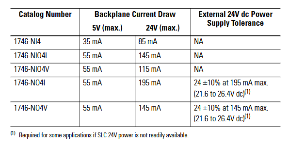
1746-NO4V 4-channel voltage (0-10V/± 10V) with the same structure as NO4I, output type is voltage, suitable for voltage control equipment, analog speed control motor, indicator light brightness adjustment
1746-NO8V 8-channel voltage (0-10V) 8-channel high-density, total output load current ≤ 100mA, supports synchronous control of multiple devices and multi-channel analog signal output (as displayed on the dashboard)
System installation and configuration
(1) Rack and power installation
Rack selection: Choose slot positions based on the number of modules. 1746-A7 (7 slots) is suitable for small and medium-sized systems, while 1746-A10 (10 slots) is suitable for large systems; If expansion is required, multiple rack connections can be achieved through the 1747-SN module.
Power calculation: It is necessary to calculate the 5V DC and 24V DC power consumption of all modules to ensure sufficient output capacity of the power module (e.g. 1746-P2 provides 24V DC 2.0A, 1746-P4 provides 4.0A). The calculation formula is: total power consumption=∑ (5V current of each module)+∑ (24V current of each module).
Installation specifications:
The rack should be installed vertically to avoid tilting (tilt angle ≤ 5 °) and ensure good heat dissipation;
The power module should be located near the input end of the rack to reduce wire voltage drop;
The grounding resistance is ≤ 4 Ω, and the rack shell needs to be separately grounded to avoid electromagnetic interference.
(2) Module installation steps
Static protection: Wear a grounding wristband before operation, store the module in an anti-static bag, and avoid touching the back panel pins.
Power off operation: Disconnect the power supply of the power rack before installation to prevent damage to the module or backplane caused by live plugging and unplugging.
Module insertion: Align the rack slot and slowly insert the module into the upper and lower self-locking tabs to secure it, without the need for additional screws; Idle slots require installation of 1746-N2 filling plates to prevent dust from entering.
Slot selection:
The processor module (such as 1747-L511) must be installed in slot 0;
Under high temperature conditions, install the heating module (such as a 32 point I/O module) in the rightmost slot (with a temperature tolerance of 60 ℃);
The analog module needs to be kept away from strong interference sources such as frequency converters and high-power motors to reduce signal fluctuations.
(3) Module address configuration
Address allocation principle:
Digital quantity module: Each 16 channel module occupies 1 input word/output word, and the 32 channel module occupies 2 input words/output words;
Analog module: Class 1 interface module (such as 1746-NI8) occupies 8 input words and 8 output words, while Class 3 interface module adds an additional status word address;
Address range: Input image area I: 0/0-I: 255/15, output image area O: 0/0-O: 255/15, avoid address overlap.
Configuration tool: Set the module ID code (such as 1746-NI8 Class 1 ID 3526) through RSLogix 500 programming software, and assign the corresponding input/output image area address. After configuration is complete, download it to the processor.
Wiring specifications and examples
(1) General Wiring Guidelines
Wire selection:
Digital module: Recommended 22-16 AWG shielded twisted pair (such as Belden 8761) to reduce electromagnetic interference;
Analog module: requires the use of twisted pair shielded wires (such as Belden 9239), with the shielding layer grounded at one end (near the signal source end) to avoid common mode interference;
Power cord: A 24V DC power supply requires the use of 18-14 AWG wires to ensure a voltage drop of ≤ 0.5V (the wire diameter needs to be increased for long-distance wiring).
Isolation and grounding:
The group isolation module needs to ensure that the common terminals (COM) of different groups are not connected together to avoid cross group short circuits;
The grounding of the analog module needs to be independent and separate from the power grounding, with a grounding resistance of ≤ 1 Ω;
The rack shell needs to be connected to the system grounding grid through grounding terminals to prevent static electricity accumulation.
Polarity and short circuit protection:
The DC module needs to strictly distinguish between positive and negative poles, and reverse connection may burn out the module (some modules have reverse connection protection);
The load end of the output module needs to be connected in series with a suitable fuse (such as 0.5A/250V) to prevent short circuit damage to the module caused by the load.
(2) Typical module wiring example
1746-IB32 (32 channel digital input):
4 sets of common terminals (COM1-COM4) correspond to channels 0-7, 8-15, 16-23, 24-31 respectively;
COM1-COM4 is connected to the negative pole of 24V DC, channels 0-31 are connected to the sensor output terminal, and+V1-V4 is connected to the positive pole of 24V DC;
When the current of a single group exceeds 2A, both common terminals of the group need to be connected simultaneously to avoid terminal overload.
1746-OB32E (32 channel digital output):
Two sets of common terminals (+V1,+V2) correspond to channels 0-15, 16-31;
- OMRON
- ABB
- General Electric
- EMERSON
- Honeywell
- HIMA
- ALSTOM
- Rolls-Royce
- MOTOROLA
- Rockwell
- Siemens
- Woodward
- YOKOGAWA
- FOXBORO
- KOLLMORGEN
- MOOG
- KB
- YAMAHA
- BENDER
- TEKTRONIX
- Westinghouse
- AMAT
- AB
- XYCOM
- Yaskawa
- B&R
- Schneider
- KONGSBERG
- NI
- WATLOW
- ProSoft
- SEW
- ADVANCED
- Reliance
- TRICONEX
- METSO
- MAN
- Advantest
- STUDER
- DANAHER MOTION
- Bently
- Galil
- EATON
- MOLEX
- DEIF
- B&W
- ZYGO
- Aerotech
- DANFOSS
- Beijer
- Moxa
- Rexroth
- Johnson
- WAGO
- TOSHIBA
- BMCM
- SMC
- HITACHI
- HIRSCHMANN
- Application field
- XP POWER
- CTI
- TRICON
- STOBER
- Thinklogical
- Horner Automation
- Meggitt
- Fanuc
- Baldor
- SHINKAWA
- Other Brands
- UniOP
- KUKA
- Iba
- Beckhoff
-
 OMRON C60H C6DR DE V1 Sysmac PLC
 -
 MITSUBISHI ELECTRIC A2ACPU21 S1 CPU Module
 -
 ABB BAILEY INNPM12 Network Process Module
 -
 HONEYWELL 620 0073C IPC PLC Module
 -
 Mitsubishi 15050 PR02B PLC Circuit Board
 -
 SIEMENS 6SY7000 0AC37 Drive Control Module
 -
 OMRON TJ2 ECT16 Traxial EtherCAT Controller
 -
 GE Fanuc IC698PSD300D Power Supply Module
 -
 Texas Instruments Series 505 16 Position Base
 -
 OMRON YASKAWA SGDH 10DE OY Servo Drive
 -
 Allen‑Bradley 440G-MT Safety Interlock Switch Specs
 -
 Rubycon PD27A 24V 8A Power Supply Module
 -
 SK-H1-GDB1-F11D PLC Gate Driver Board Kit
 -
 VIPA 441-4UA14 451-4UA14 PLC Module Rack
 -
 Mitsubishi FX5U-80MT ESS PLC Controller Specs
 -
 Mitsubishi Q64TCRTN Temperature PLC Module
 -
 GE 1C31170G Rev10 PLC Circuit Board Module
 -
 Schneider TWDLMDA40DTK PLC Controller Module
 -
 Omron FQM1-MMA22 Motion Control Module Specs
 -
 OMRON CJ1W-NCF71 Position Control Unit Specs
 -
 Schneider TSXETY4103 Ethernet Module
 -
 Mitsubishi Q12PHCPU Process CPU
 -
 Yaskawa 3G3HV-A4022-CE AC Drive
 -
 Cincinnati Milacron 3-533-0669G Temperature Control Board
 -
 Allen Bradley 20AC030A3AYNANC0 PowerFlex 70 Drive
 -
 Siemens 6ES7314-6BG03-0AB0 CPU 314C-2 DP
 -
 Carrier 17EX54007903 PLC Module
 -
 OMRON CS1W-V600C12 ID Controller Module
 -
 Honeywell 51402755-100 PCB Card
 -
 Heidenhain ECN 113 Rotary Encoder
 -
 OMRON B7AM-8B16 I/O Terminal Block
 -
 Fanuc A06B-6110-H026 Power Supply Module
 -
 Schneider TSXETG3021 Ethernet Gateway
 -
 OMRON CS1W-CLK21-V1 Controller Link Unit
 -
 NP1W6406T-Z704 PLC I/O Module
 -
 OMRON CJ1W-DA08C Analog Output Module
 -
 Yaskawa 3G3HV-A4022-CE AC Drive
 -
 OMRON NB7W-TW01B CP1L-EL20DR-D Power Panel
 -
 OMRON C500-NC103-E Position Control Unit
 -
 Steag Hamatech PLC DCS Servo Control System
 -
 Siemens 6SN1123-1AA00-0DA1 Power Supply Module
 -
 GE IC693CHS391H CPU & AD693CMM301A PLC Module
 -
 Siemens 6FC5303-0AF23-1AA1 PLC Control Panel
 -
 Square D CM4000T PowerLogic Circuit Monitor J1 F16
 -
 Siemens 6FX5002-5DG10-1BA0 MOTION-CONNECT 500 Cable
 -
 Schmersal SRB324ST 101195504 Safety Relay 24V
 -
 Mitsubishi 15050-PR02A PLC Circuit Board Module
 -
 OMRON CQM1-AD041 Analog Input PLC Module
 -
 Beckhoff EL5042 EtherCAT PLC Terminal Module
 -
 OMRON C200HW-MC402-E Motion Control Unit
 -
 C36TC0UA1100 Industrial Temperature Controller
 -
 NL8048BC24 12 Industrial Control LCD Module
 -
 OMRON R88D Servo Drive and Motor System
 -
 OMRON CS1W CLK21 V1 Controller Link Module
 -
 OMRON YASKAWA R7M A20030 S1 D Servo Motor
 -
 SIEMENS 6AV2128 3KB06 0AX1 Unified Comfort Panel
 -
 Schneider Electric METSEPM8240 PowerLogic Meter
 -
 Advanced AMCI 1PLC 1 31F Programmable Limit Switch
 -
 ABB PM582 ETH Programmable Logic Processor
 -
 SIEMENS 6FC5110 0CB01 0AA0 CPU Control Board
 -
 Schleicher P03GS13A CPU Module
 -
 Siemens 6SN1123-1AA00-0BA1 Power Module
 -
 Mitsubishi A1S61PN Power Supply Module
 -
 Yaskawa CPS-IONB DC Power Supply Module
 -
 Siemens 6ES7215-2BD00 CPU 215-2
 -
 Mitsubishi A2ACPU MELSEC PLC System Kit
 -
 ProSoft 3150-MCM Communication Module
 -
 Mitsubishi OSE104ET Incremental Encoder
 -
 OMRON CJ1W-AD081-V1 Analog Input Module
 -
 Broadcom BCM5464A1KRB Quad Port Ethernet IC
 -
 Modicon M221-24IO TM221C24 PLC 24 PNP Transistor
 -
 Allen-Bradley 1321-3R160-B Line Reactor 3R160B
 -
 Beckhoff CX1020-0012 Embedded PLC Module Specs
 -
 Turck BL20-PF-24VDC-D Power Feed Module Specs
 -
 Siemens 6SY7000-0AC37 Power Supply Module
 -
 Yaskawa SGDH-10DE-OY 1kW 400V Servo Drive Specs
 -
 Omron 3G3SV-BB015-E 1.5kW 220V VFD Specs
 -
 Uni-Pro CPU91-PLC J 23.020167X Processor Module
 -
 PASABAN MTC-3044 PLC Rack Power Supply 4835-A
 -
 XYCOM 3015T Operator Interface Panel BIN4.4.4
 -
 OMRON CJ1W-MD261 Mixed I/O Module
 -
 Omron NJ301-1100 PLC CPU eCat EIP Specs
 -
 Omron F500-C15-ETN Vision System PLC Module
 -
 Modicon M241-24IO TM/T2UK PLC with Ethernet
 -
 SIXNET YS-800-001 RTU PLC Module
 -
 BEMAC UST-202-D Interface Board 1307D V08B2
 -
 Yaskawa JANCD-MMOIC-02 Drive Circuit Board
 -
 ABB 3BSE005028R1 SDCS-COM-1 Comm Board
 -
 Omron 3G3MX2-A4110 A4150 Inverter Drives Specs
 -
 KEYENCE CA-E100 PLC Module
 -
 GE IC693ALG223-GB Analog Input Module Specs
 -
 ABB BAILEY IMMFP01 Multi Function Processor System
 -
 SIEMENS 6FC5372 0AA00 0AA1 NCU 7202 Controller
 -
Modicon TM241CE4 40I O Transistor Programmable Controller
-
 SIEMENS 6ES7 315 2EH13 0AB0 CPU 3152 PN DP
 -
 NORIS A1 91 PCB Card Rack Module System
 -
 SIEMENS 6ES7 313 5BE01 0AB0 Compact CPU
 -
 SCHNEIDER ELECTRIC S144B MICROLOGIC 60A Trip Unit
 -
 CNI PLC269 v3 Control Module Board Rev H
 -
ABB BAILEY IIMCP02 Processor Module
-
 OMRON NT20S ST121 EV3 Operator Interface Terminal
 -
 OMRON NS-CA001 Video Input Unit
 -
 GE Fanuc IC695CHS012 RX3i Backplane
 -
 Allen Bradley 2711E-K14C6 PanelView 1400e Terminal
 -
 Siemens Sinamics CCB 10000432.71 Power Cell
 -
 Siemens 6SL3210-1SE21-8UA0 Power Module PM340
 -
 Yaskawa CIMR-F7A20P4 AC Drive
 -
 Beckhoff EP1918-0002 EtherCAT Box I/O Module
 -
 OMRON CQM1-TC001 Temperature Control Module
 -
 GE Fanuc SGHA36AT0400 Industrial Contactor
 -
 OMRON NJ501-1500 PLC Machine Automation Controller
 -
 Mitsubishi MAZAK QX084 Power Supply MELDAS 500 CNC
 -
 B&R 0AC808.9 PLC Automation Module
 -
 OMRON CP1H-XA40DT1-D PLC Module
 -
 G&W Electric PLC15 5111 011 15kV Capnut Assembly
 -
 GE DS200SLCCG3AGH PCB Circuit Board
 -
 Siemens SINUMERIK 6FC3981-4FD PLC Extension
 -
 OMRON F300-DC I/O Image Processing Unit
 -
 FANUC A06B-0314-B002 AC Servo Motor
 -
 GC-S84 Programmable Controller Logic Module
 -
 PASABAN MONTELEC MTC3001-DC Drive Control PLC
 -
 Allen Bradley 100E460EJ11 Auxiliary Contactor
 -
 Bosch Rexroth 1070075337-101 Card Parameters
 -
 HMS Anybus AB7646-F Gateway Specifications
 -
 Bosch 062633-303401 CNC Servo PLC Card
 -
 TI 500-5023 Series PLC Power Supply
 -
 Siemens C98043-A7002-L1-12 Circuit Board
 -
 Omron E5CC-RX3A5M-000 Controller


