Allen-Bradley SLC 500 ™ Installation Guide for 32 Channel Digital I/O Module
Core restriction: Live replacement of components or wiring is prohibited in hazardous environments. Component replacement must use original factory accessories, otherwise it may damage the explosion-proof characteristics.
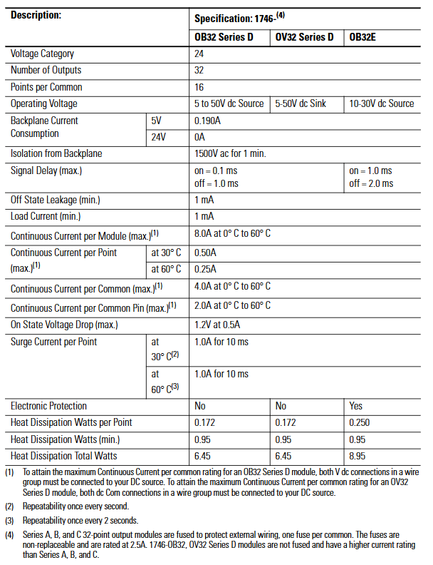
The total heat dissipation power is 6.45W (0.172W per point, minimum 0.95W), 8.95W (0.250W per point, minimum 0.95W), and 6.45W (0.172W per point, minimum 0.95W)
Fuse protection (Series A/B/C): 1 non replaceable 2.5A fuse per group, Series D: None (relying on electronic protection): 1 non replaceable 2.5A fuse per group, Series D: None
Key supplement (OB32E electronic protection features)
Protection principle: Based on thermal cut-out technology, in the event of a short circuit or overload, the faulty channel limits current within milliseconds, while other channels operate normally, and the E-Fuse LED lights up to sound an alarm.
Automatic reset: After the fault is removed, the channel cools down below the threshold and automatically recovers; Or power off and restart the module to reset, without the need to manually replace the fuse.
Limitations: It does not protect against reverse polarity wiring or AC power connection, and requires external circuit breakers to meet safety regulations.

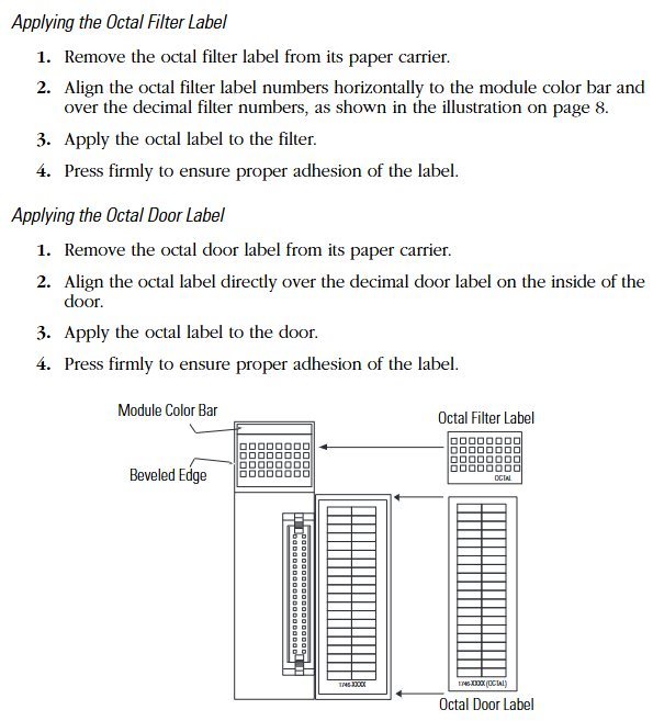
Octal Label Kit Installation (PLC Processor Only)
(1) Composition and purpose of the kit
Contains components: octal filter label, octal door label, used to replace the default decimal label of the module and adapt to the octal addressing requirements of the PLC system.
Acquisition method: It is necessary to order separately from Allen Bradley dealers, and the model must match the I/O module catalog number (refer to manual 1747-UM011 or ACIG-PL001 price list).
(2) Installation steps
Filter label: Peel off the label from the carrier paper, align the module color bar horizontally, cover decimal numbers, and press to fix.
Door label: After peeling off, directly cover the decimal label on the inside of the chassis door to ensure consistent addressing identification.
Wiring scheme and operating specifications
(1) Comes with connector wiring (Option 1:1746-N3 connector)
The components include: the module comes standard with a 40 pin female connector with keys (1746-N3) and crimping pins, supporting 22-26 AWG wires.
Pin assembly steps:
Stripping: Strip off the insulation layer of 4mm (5/32 inch) wire to expose the conductor.
Plug in: Insert the wire into the pin to the "wire stop" position.
Crimping: Use DDK 357J-5538 crimping tool (or Amp 90418-1 equivalent tool) for crimping; When there are no tools available, use sharp nose pliers to press the wire barrel and insulation barrel together, and then weld and fix them with 60% tin/40% lead rosin solder.
Fixed: Insert the pin into the connector, gently pull the wire to confirm that the "tang" is locked to prevent detachment.
Connector installation: Align the keyway of the module male connector (MIL-C-83503 standard) and lock it by pressing the upper and lower retaining arms.
(2) 1492 Wiring System (Option 2: Pre wiring Scheme)
1. System composition and advantages
Core components: 1492-CABLExx pre wired cable (with four lengths of 0.5m/1.0m/2.5m/5.0m), 1492-IFM40xx DIN rail terminal block (with/without LED status light), no need for on-site crimping, improving wiring efficiency.
Voltage drop reference (30 ℃/60 ℃):
Cable model: Voltage drop of power/common terminal wire (2A), voltage drop of output channel wire (0.5A), voltage drop of power/common terminal wire (2A), voltage drop of output channel wire (0.5A)
1492-CABLE005H 127mV 34mV 144mV 38mV
1492-CABLE10H 173mV 45mV 196mV 51mV
1492-CABLE25H 334mV 83mV 388mV 95mV
1492-CABLE50H 574mV 147mV 686mV 169mV
2. Terminal block label specifications
Label kit: The 1492 terminal block comes with multiple sets of sticker labels, indicating the module model (such as 1746-IB32) and the position of the "upper/lower" terminal block, distinguishing SLC (decimal) and PLC (octal) addressing.
Paste requirements: Select the corresponding label according to the module model and paste it on the outside of the terminal block. For example, label the "+V3" and "IN16" on the "upper" terminal block of module 1746-IV32 to ensure that the wiring corresponds.
(3) General Wiring Guidelines
Group isolation maintenance: When using the 1492 terminal block, it is necessary to choose a model that supports "group isolation" (such as with grouping partitions) to avoid signal crosstalk between different groups.
Voltage drop control: Calculate the total voltage drop (wire resistance x current x length) to ensure that the output module load terminal voltage is not lower than the minimum conduction voltage (such as 1.2V for OB32).
Public end connection:
Input module (IB32): Each group has 2 interconnected DC Com pins, which can be connected to only 1 pin; When it needs to exceed 2A, 2 should be connected.
Output module (OB32/OV32): Each group has 2+V DC (or DC Com) pins internally connected. When the current exceeds 2A, 2 pins must be connected to avoid pin overload.

Wiring diagrams and addressing instructions
(1) Core identification of diagrams
Double digit labeling: Each wiring diagram is labeled with both decimal (SLC system) and octal (PLC system) addresses, such as "IN 14" for SLC corresponding to "16 (octal)" for PLC.
Grouping division: Use "Wire Group 1-4" (input) or "Wire Group 1-2" (output) to clarify the wiring grouping, and the correspondence between the common terminal (COM1-4) and the signal terminal (IN/OUT 0-31) is clear.
- ABB
- General Electric
- EMERSON
- Honeywell
- HIMA
- ALSTOM
- Rolls-Royce
- MOTOROLA
- Rockwell
- Siemens
- Woodward
- YOKOGAWA
- FOXBORO
- KOLLMORGEN
- MOOG
- KB
- YAMAHA
- BENDER
- TEKTRONIX
- Westinghouse
- AMAT
- AB
- XYCOM
- Yaskawa
- B&R
- Schneider
- Kongsberg
- NI
- WATLOW
- ProSoft
- SEW
- ADVANCED
- Reliance
- TRICONEX
- METSO
- MAN
- Advantest
- STUDER
- KONGSBERG
- DANAHER MOTION
- Bently
- Galil
- EATON
- MOLEX
- DEIF
- B&W
- ZYGO
- Aerotech
- DANFOSS
- Beijer
- Moxa
- Rexroth
- Johnson
- WAGO
- TOSHIBA
- BMCM
- SMC
- HITACHI
- HIRSCHMANN
- Application field
- XP POWER
- CTI
- TRICON
- STOBER
- Thinklogical
- Horner Automation
- Meggitt
- Fanuc
- Baldor
- SHINKAWA
- Other Brands


