Allen Bradley 1746-NI8 Analog Input Module Application Case
Allen Bradley 1746-NI8 Analog Input Module
Product Core Positioning and Characteristics
(1) Basic positioning
1746-NI8 is an 8-channel analog input module of the SLC 500 series, used to collect DC voltage or current signals from industrial sites (such as sensor and transmitter outputs), convert analog signals into digital signals recognizable by PLC through built-in analog-to-digital (A/D) converters, achieve equipment status monitoring and process control, and adapt to fixed and modular SLC 500 processors.
(2) Core functions and hardware features
Category specific description
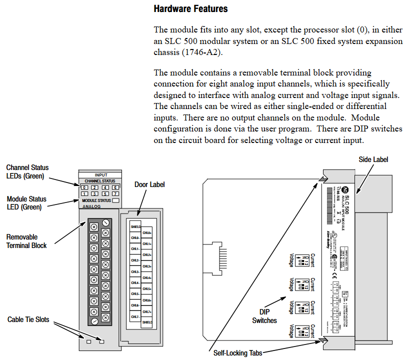
Hardware design -8 high impedance input channels, supporting single ended or differential wiring;
-Comes with a detachable terminal block (spare part number 1746-RT25G) for easy wiring and maintenance;
-The panel contains 9 green LED indicator lights: 8 channel status lights (corresponding to 8 input channels), 1 module status light, which intuitively displays the operation and fault status;
-Side mounted DIP switch for selecting channel input type (voltage/current).
System compatibility - supports two interface modes, Class 1 and Class 3:
-Class 1 (default): Suitable for SLC 500 fixed type, SLC 5/01/02/03/04 processors, occupying 8 output configuration words and 8 input data words;
-Class 3 (Advanced): Only compatible with SLC 5/02/03/04 processors, with additional support for user-defined scaling and channel status word monitoring, occupying 12 output configuration words and 16 input words (including 8 data words and 8 status words).
Key feature - Automatic calibration: All enabled channels undergo continuous temperature compensation and automatic calibration without the need for manual triggering;
-Fault diagnosis: supports fault detection such as open circuit, over range, and configuration errors, and provides feedback through LED and status words;
-Filtering function: Programmable digital low-pass filtering (8 frequencies to choose from), balancing noise suppression and response speed.

Quick Start Guide
For users with experience using SLC 500, a simplified deployment process is provided, with the following core steps:
Equipment preparation: Screwdrivers, analog input devices (such as sensors), shielded cables (recommended Belden 8761), SLC processors and power supplies, and programming equipment (such as RSLogix 500) need to be prepared.
Hardware inspection: Confirm that the packaging contains 1746-NI8 modules and pre installed terminal blocks. If missing, please contact the supplier.
Power compatibility: The module is powered through the backplane and consumes 5V DC 200mA and 24V DC 100mA. It is necessary to ensure that the chassis power load is sufficient (refer to manual 1747-6.2 to calculate the total load).
DIP switch setting: Adjust the side DIP switch (OFF=voltage, ON=current) according to the input type (voltage/current).
Module installation: Insert the chassis into any non processor slot while powered off (it is recommended to install it in the rightmost slot in high-temperature environments for higher temperature tolerance), and tighten the self-locking buckle.
Wiring: Use shielded cables to connect the sensor to the terminal block. Single ended signals can be short circuited to the common terminal, while differential signals should pay attention to the common mode voltage (≤± 10.5V). The shielding layer should be grounded at one end (channels 0-3 should be connected to the top shielding terminal, and channels 4-7 should be connected to the bottom).
System configuration: Set the module ID code (3526 for Class 1 and 12726 for Class 3) through programming software. Class 3 requires an additional configuration of 16 input words and 12 output words.
Channel configuration: Define channel configuration words (such as input type, data format, filtering frequency) in the ladder program, and download them to the module output image area through the COPY instruction.
Startup verification: It is normal for the module status light and the enabled channel light to remain on after power on; If the light flashes or does not light up, refer to Chapter 7 for troubleshooting.
Installation and wiring
(1) Installation specifications
Static protection: Wear a grounding wristband during operation to avoid touching the back panel pins, and store in an anti-static bag when idle.
Slot selection:
Modular chassis: can be installed in any slot except slot 0 (processor slot);
Fixed expansion chassis (1746-A2): Please refer to the compatibility table (if combined with OB16 module, confirm current load), and some combinations require external power supply.
Temperature adaptation: The working temperature of the regular slot is 0-55 ℃, and the rightmost slot is 0-60 ℃. Avoid approaching high heating modules (such as 32 point I/O modules) or strong interference sources (such as frequency converters).
Installation steps: Align the upper and lower guide slots of the chassis, slowly push them into the buckle lock, and install the 1746-N2 filling plate in the idle slot.
(2) Wiring requirements
Specification for Wiring Types
The terminal block has 18 detachable terminals, including 2 shielded terminals, supporting up to 14 AWG wires, and terminal screw torque ≤ 5 lb in (0.565 Nm).
- ABB
- General Electric
- EMERSON
- Honeywell
- HIMA
- ALSTOM
- Rolls-Royce
- MOTOROLA
- Rockwell
- Siemens
- Woodward
- YOKOGAWA
- FOXBORO
- KOLLMORGEN
- MOOG
- KB
- YAMAHA
- BENDER
- TEKTRONIX
- Westinghouse
- AMAT
- AB
- XYCOM
- Yaskawa
- B&R
- Schneider
- Kongsberg
- NI
- WATLOW
- ProSoft
- SEW
- ADVANCED
- Reliance
- TRICONEX
- METSO
- MAN
- Advantest
- STUDER
- KONGSBERG
- DANAHER MOTION
- Bently
- Galil
- EATON
- MOLEX
- DEIF
- B&W
- ZYGO
- Aerotech
- DANFOSS
- Beijer
- Moxa
- Rexroth
- Johnson
- WAGO
- TOSHIBA
- BMCM
- SMC
- HITACHI
- HIRSCHMANN
- Application field
- XP POWER
- CTI
- TRICON
- STOBER
- Thinklogical
- Horner Automation
- Meggitt
- Fanuc
- Baldor
- SHINKAWA
- Other Brands


