
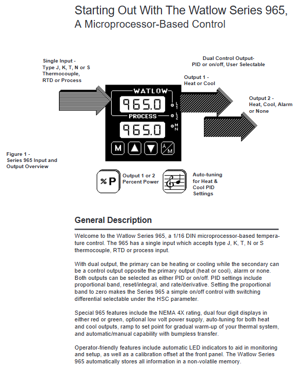
Watlow Series 965 Controller
4-20mA process output (output 1, model 965A-3F-00): terminal 9 is connected to the positive pole, terminal 10 is connected to the negative pole, and the maximum load is 800 Ω. It can be used to drive valves, recorders, and other equipment.
Typical heating control system wiring example: Controller terminals 11/12 are connected to a 120V AC power supply, terminals 3/5 are connected to a J-type thermocouple, terminals 10/1 are connected to a solid-state relay (SSR) control terminal, and the SSR output terminal is connected to a heater and a 240V AC power supply. At the same time, a Series 92 limit controller (terminals 13/14) is connected in series to achieve over temperature protection, and terminal 7 is connected to an alarm light (which lights up when a high temperature alarm is triggered).
Operation interface and menu configuration
(1) Button and display functions
Key definition
MODE key: Switch operation menu parameters. In automatic mode, if there is no operation for 5 seconds, the parameter change will be automatically confirmed.
Up and down arrow keys: Adjust parameter values (short press to increase or decrease by 1, long press to quickly increase or decrease), while long press for 3 seconds to enter the settings menu, continue long press to enter the calibration menu.
A/M key: Short press to clear the lock alarm, press twice continuously within 2 seconds to switch between automatic/manual mode. In manual mode, the lower screen displays the output power (-100% to 100%).
Display screen and indicator lights
Upper screen: Red/green 4-digit LED, displaying process value (PV), parameter value or error code (such as "----" indicating sensor failure).
Lower screen: red/green 4-digit LED, displaying set value (SP), parameter name (such as "LOC" "Pb1"), alarm information ("LO" "HI") or error code (such as "Er7").
Indicator lights: L1 (red) on indicates output 1 activation, L2 (red) on indicates output 2 activation, MN (green) on indicates manual mode, flashing indicates pending mode switch.
(2) Core menu configuration
1. Setup Menu
Entry method: Simultaneously press and hold the up and down arrow keys for 3 seconds, the lower screen will display "LOC", and the upper screen will display the current lock level. The main parameters are as follows:
Parameter Function Range Default Values Precautions
LOC operation permission lock 0-4 0 level: full permission; Level 4: Only view PV/SP, non adjustable
In the input type selection J/K/t/n/S/rtd/rt.d/0-5/420 J, it needs to be consistent with the internal DIP switch (DIP switch is located on the left side of the chassis, view from the bottom)
Temperature unit C/F F (US mode)/C (SI mode) displayed only when input as thermocouple/RTD
The upper and lower limits of the rL/rH range, where rL<rH, depend on the input type. When the input type defaults to the range process signal, rL corresponds to 0V/4mA, and rH corresponds to 5V/20mA
Ot1 output 1 function ht (heating)/CL (cooling) ht heating is the reactive effect (output activated when PV<SP), cooling is the positive effect
Ot2 output 2 function Con/PrA/Pr/dEA/dE/no Con Con: opposite function to output 1; PrA: with display process alarm
HSC switch control hysteresis of 1-99/0.1-9.9/0.01-0.99 3 (° F)/2 (° C) takes effect when Pb1=0, avoiding frequent output switching
RP slope function Str/On/OFF Str: only heats up during startup; On: Setting value changes also increase temperature
Display when rt slope rate 0-9999 100 (°/hour) rP ≠ OFF
2. Operation Menu
Entry method: Press the MODE key to switch, the main parameters are as follows:
Parameter Function Range Default Values Precautions
SP control set value rL-RH 75 (° F)/24 (° C) displays the target set value in ramp mode, and the actual value gradually approaches
Pb1/Pb2 ratio with 0-999 (° F/° C/unit)/0-0999.9% (span) 25 (° F)/3% (span) Pb1=0 is switch controlled, Pb2 is only displayed when Ot2=Con
RE1/It1 integral (reset) rE1: 0.00-99.9 (times/minute); It1: 0.0-99.9 (minutes/time) 0.00 Eliminate static deviation between PV and SP, excessive deviation can easily lead to oscillation
RA1/dE1 differential (rate) 0.00-9.99 (minutes) 0.00 suppresses overshoot, which can lead to slow response if it is too large
Ct1/Ct2 cycle time 0.1-999.9 (seconds) 5.0 Mechanical relays are recommended to last for 5-60 seconds, while solid-state relays can last for 0.1-5 seconds
ALO/AHI alarm upper and lower limits ALO < AHI, according to the alarm type, the deviation alarm of -999/999 is the offset relative to SP (e.g.+5 represents SP+5)
AUt self-tuning 0 (off)/1 (slow)/2 (medium)/3 (fast) 0. After starting, the Lower screen alternately displays "At", and automatically resets to 0 after completion
3. Calibration Menu
Entry method: Starting from the LOC parameter in the settings menu, continue to press and hold the up and down arrow keys simultaneously. The lower screen will display "CAL" and the upper screen will display "no". Press the up arrow key to change to "YES" and then press the MODE key to enter. Main functions:
Input calibration: For two-point calibration of thermocouples (input 0.00mV, 50.00mV), RTDs (input 44.01 Ω, 255.42 Ω), and process signals (0.000V/4.00mA, 5.000V/20.00mA), a precision signal source is required.
- OMRON
- ABB
- General Electric
- EMERSON
- Honeywell
- HIMA
- ALSTOM
- Rolls-Royce
- MOTOROLA
- Rockwell
- Siemens
- Woodward
- YOKOGAWA
- FOXBORO
- KOLLMORGEN
- MOOG
- KB
- YAMAHA
- BENDER
- TEKTRONIX
- Westinghouse
- AMAT
- AB
- XYCOM
- Yaskawa
- B&R
- Schneider
- KONGSBERG
- NI
- WATLOW
- ProSoft
- SEW
- ADVANCED
- Reliance
- TRICONEX
- METSO
- MAN
- Advantest
- STUDER
- DANAHER MOTION
- Bently
- Galil
- EATON
- MOLEX
- DEIF
- B&W
- ZYGO
- Aerotech
- DANFOSS
- Beijer
- Moxa
- Rexroth
- Johnson
- WAGO
- TOSHIBA
- BMCM
- SMC
- HITACHI
- HIRSCHMANN
- Application field
- XP POWER
- CTI
- TRICON
- STOBER
- Thinklogical
- Horner Automation
- Meggitt
- Fanuc
- Baldor
- SHINKAWA
- Other Brands
- UniOP
- KUKA
- Iba
- Beckhoff
-
 Basler DECS-100-B15 Digital AVR
 -
 Basler 9284900103 PS DECS-400N
 -
 Basler D4N3H1U Intertie Protection
 -
 Basler DECS-100-B15 A15 AVR
 -
 Basler KR4F Voltage Regulator
 -
 Basler BE26434 T14 Transformer
 -
 Basler SR8A-2B15B3A Regulator
 -
 Westinghouse 774B472A12 AR Relay
 -
Basler DECS-100-B15 AVR
-
 Basler XR2002F Regulator 110V
 -
 Basler SR125-E Static Regulator
 -
 Basler SSR 125-12 Regulator
 -
 Basler MOC2599 Motor Pot
 -
 Basler BE1-DFPR Feeder Relay
 -
 Basler CBS 305 Current Boost
 -
 Basler BE1-25 AutoSync
 -
 Basler MVC 300 Voltage Control
 -
 Basler BE3-25A AutoSync
 -
 Basler KR7FF Static Regulator
 -
 Basler 90-49000-100 Regulator
 -
 Basler 880 kVA Dry Type Transformer Specs
 -
 Basler Electric BE1-25 Sync-Check Relay Specs
 -
 Basler SSR 125-12 Voltage Regulator Specs
 -
 Basler Electric BE1-851 Overcurrent Relay Review
 -
Basler Electric 149D930G02 Control Sub-Assembly
-
 Basler Electric BE1-81O/UT Frequency Relay Specs
 -
 Basler Electric BE1-51/27C Overcurrent Relay
 -
 Basler Electric 149D956G02 Industrial Component
 -
Basler Electric BE1-51A Overcurrent Relay Specs
-
 Basler Electric BE1-40Q Loss of Excitation Relay
 -
 Basler DECS-200 Excitation Control System
 -
 Basler DECS-200 Voltage Regulator 56-277V AC / 125V DC
 -
 Basler BE1-87T Transformer Differential Relay
 -
 Basler RDP-110-S1 Protection Relay
 -
 Basler BE1-700V Digital Protective Relay
 -
 Basler BE1-951 Overcurrent Protection System
 -
 Basler DECS-300 Digital Excitation Control
 -
 Basler DECS-200 Digital Excitation Control
 -
 Basler DECS-200-1C Excitation Control System
 -
Basler DECS-200-1L Digital Excitation Control
-
 Basler Electric BE1-GPS Generator Protection System
 -
Basler Electric DECS-200-1C Digital Excitation Controller
-
 Basler Electric DECS125-15 Excitation Control with Power Module
 -
 Basler Electric BE1-87G Differential Relay
 -
 Basler Electric BE1-11 Protection System I5A3M2P2N0EA00
 -
Basler Electric DECS-200-1C Excitation Control System
-
Basler Electric BE1-11g Generator Protection Relay
-
 Basler Electric DECS 125-15-B2C1 V2.0.9 Excitation Control
 -
 Basler Electric BE1-81O/UT3ED1JA7N2F Frequency Relay
 -
Basler Electric BE1-81O/UT3EE1YB7N1F Frequency Relay
-
 Basler Electric DECS-200-1L Digital Excitation Control System
 -
Basler DECS125-15-B2C1 Excitation Control
-
 Basler 9507900205 SSR Retrofit Voltage Regulator
 -
 Basler BE2000E Digital Voltage Regulator
 -
 Basler BE1-GPS Generator Protection System
 -
Basler DECS-250-CN1CN1N Digital Excitation Control
-
 Basler DGC-2020 Genset Controller
 -
 Basler BE1-81O UT3ED1LA7N0F Frequency Relay (Variant)
 -
 Basler BE1-81O UT3EE1YA9S0F Frequency Relay (Variant)
 -
Basler BE1-81O Over/Under Frequency Relay
-
Basler DECS125-15 Digital Excitation Control
-
Basler Electric BE1-951 Overcurrent Protection System
-
 Basler Electric BE1-700V Digital Protective Relay
 -
 Basler Electric APR63-5 Automatic Voltage Regulator
 -
Basler Electric BE1-851 Overcurrent Protection System
-
Basler Electric DECS-250-LN1SN1N Excitation Control
-
 Basler Electric BE1-87T Transformer Differential Relay
 -
Basler Electric DECS-200-1L Excitation Control System
-
 Basler Electric 9310300100 DECS-300 Excitation Control
 -
 Basler Electric SSE-N 125-4.5KW Shunt Exciter Regulator
 -
 Basler Electric DGC-2020HD-5NS1DNSBA Genset Controller
 -
Basler Electric BE1-81-O/UT3EE1JB7N1F Frequency Relay
-
Basler Electric BE1-81T1EE1WA0N1F Frequency Relay
-
 Basler Electric BE1-25M1EA6PN5R1F Sync-Check Relay
 -
 Basler Electric BE1-GPS Generator Protection System
 -
Basler Electric DECS-250-LN1SN1N Excitation Control Rev V
-
 Basler Electric DECS-250-CN2CN1N Excitation Control
 -
Basler Electric BE1-50/51B-207 Overcurrent Relay
-
Basler Electric DECS-300-C0N0 Excitation Control System
-
Basler Electric DECS-200 Digital Excitation Control System
-
Basler Electric DECS-250-LN1CN1N Excitation Unit
-
Basler Electric DECS-250 LN2SA1D Excitation Unit Specs
-
Basler Electric BE1-87T Transformer Relay Review
-
Basler Electric BE1-11 Protection System
-
Basler Electric BE1-GPS100-E4N1H1N Protection System
-
 Allen-Bradley 442G-MABH-R Safety Module
 -
 Beckhoff CX1030-0111 PLC Assembly Profile
 -
 FANUC IC693CPU364 PLC Module
 -
 Orange Denmark Type 200816 220 PLC Specs
 -
 OMRON C200H-SNT31 Sysmac PLC Module
 -
 Allen Bradley 20AB022A3AYNANC0 PowerFlex 70
 -
 OMRON C200HW-PCU01 Position Control Unit
 -
 ABB AO845A-eA Analog Output Module
 -
 OMRON CJ1M-CPU22 CPU Unit
 -
 Allen Bradley 100-E265ED11 Contactor
 -
 Honeywell 51304511-100 Interface Module
 -
 SOLEXY BXF3S0101N0018 Gateway Module
 -
 OMRON CJ2H-CPU65 CPU Unit
 -
 Automation Direct GS2-45P0 AC Drive
 -
 M68-2000 2-Axis Motion CNC Controller
 -
 OMRON CJ1M-CPU11 V3.0 PLC CPU Unit
 -
 OMRON CJ1W-NC413 4-Axis Positioning Controller
 -
 OMRON 3G2A3-PRO16 Programming Console HMI
 -
 Siemens 3VT8440-2AA04-2GA2 Molded Case Circuit Breaker
 -
 Siemens 3RT5045 Contactor Series
 -
 OMRON C200HS-CPU01-E SYSMAC PLC Controller
 -
 OMRON C500-NC103-E Positioning Control Unit
 -
 OMRON CJ1W-TC001 Temperature Control Unit
 -
 OMRON NJ301-1100 NJ-PA3001 PLC System EtherCAT
 -
 Pilz 773100 M1P Safety Relay Base Unit
 -
 Siemens SINUMERIK 840D SL NCU 720.3B with PLC 317-3 PN/DP
 -
 Siemens 6AV6618-7GD01-3AB0 HMI Panel
 -
 OMRON F150-C15E-3 Vision Mate Controller PLC Overview
 -
 Mitsubishi MELSEC A Series PLC System A63P A3ACPU A616AD A68RD3
 -
 M68-2000 2 Axis Motion Controller SCE SERVO CNC
 -
 OMRON FZ-S2M PLC Camera Vision System
 -
 VISOLUX SLVA-4K PLC Module from Elektronik GmbH
 -
 OMRON CJ1M-CPU23 V2.0 PLC CPU Unit
 -
 ABB AI86-16CHF PCB Card 5761751-9 B Specifications
 -
 Allen-Bradley 100-D140ZJ22L Contactor Overview
 -
 Merlin Gerin PB80 PLC Rack
 -
 WEIR WE203 Power Supply PLC
 -
 OMRON NX-TS3102 Temperature Input Unit
 -
 Siemens 6ES7146-6FF00-0AB0 I/O Module
 -
 Fanuc A16B-3300-0057 Circuit Board
 -
 OMRON CJ1W-IDP01 Input Module
 -
 Siemens 6FX2007-1AD13 Handheld Unit
 -
 Gems EM54 PLC Module PCB


