
Honeywell System 57 5704 Control System
System operation and core functions
1. Basic operating procedures
(1) System startup and initialization
Power off inspection: Before starting, confirm that all control cards and interface cards have been correctly installed, the wiring is not loose, and the power supply voltage meets the requirements of 18-32V DC.
Step by step power on: First, connect the DC input card power supply and check that the green power light on the engineering card is always on (indicating that the power supply is normal); Insert the control cards one by one and observe that the "INHIBIT" light on each card lights up (the suppression period starts for about 30 seconds). After the suppression period ends, the light goes out and the system enters normal monitoring mode.
Sensor signal verification: Use the engineering card "BEAD mA" (catalytic card) or "SIGNAL" (4-20mA card) function to check if the sensor signal is normal (such as catalytic card bridge current of 200mA, 4-20mA card signal within normal range).
(2) Alarm and reset operations
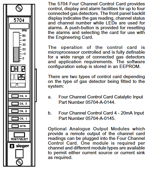
Alarm recognition: Determine the alarm type through the control card LED light——
Red flashing: A1 (1 time/second), A2 (2 times/second), A3 (3 times/second) concentration alarm; STEL/LTEL alarm (1 second on/1 second off, slow flashing).
Yellow flashing: sensor malfunction, circuit malfunction; Yellow constantly on: Channel suppressed (manual/remote suppression).
Reset operation:
Normal reset: Short press the "RESET/SET" button on the control card to clear inactive lock alarms, fault prompts, and peak displays.
Extended reset: Long press the "RESET/SET" button for 5 seconds to clear the maximum/minimum concentration record, STEL/LTEL timer, and reset the delay relay.
2. Engineering calibration and maintenance
(1) Key calibration steps (unlocked with engineering key)
Zero point calibration (ZERO):
Place the sensor in a clean environment without target gas (such as fresh air) and wait for the signal to stabilize (the control card displays the "Stable" icon).
Select the target channel, press the "ZERO" button on the engineering card, and the system will automatically set the current signal to zero. After calibration, the channel suppression needs to be released.
Range Calibration (SPAN):
Introduce a standard gas of known concentration (recommended concentration ≥ 40% of full range) and wait for the sensor signal to stabilize.
Press the "SPAN" button on the engineering card to adjust the numerical display to the standard gas concentration. After confirmation, the system saves the range parameters and updates the calibration date.
First range calibration (1st SPAN): For new catalytic sensors, record the initial sensitivity for subsequent sensor life monitoring (triggering a "life expiration" alarm when the sensitivity drops to 50% of the initial value).
(2) Key points for regular maintenance
Monthly inspection: Clean the surface dust of the module, check the tightness of the wiring terminals, and verify whether the alarm relay operates normally.
Annual calibration: Perform zero and range calibration according to sensor type (catalytic/4-20mA), check the accuracy of the engineering card clock, and print maintenance records (via RS232 printer).
Sensor replacement: It is recommended to replace catalytic sensors every 1-2 years, and 4-20mA sensors should be replaced according to the manufacturer's requirements. After replacement, the "1st SPAN" calibration needs to be performed again.

System configuration and scalability
1. Flexible configuration options
Alarm logic configuration: supports multiple alarm modes——
Independent alarm: Single channel alarm does not affect other channels;
Zoned alarm: Any channel alarm within the designated area triggers the overall alarm of the zone;
Voted alarm: Multiple channels alarm simultaneously (such as 2/3 channel alarm) to trigger the total alarm, avoiding single sensor false alarms;
Update alarm: Even if there are unreset alarms, new alarms can still trigger prompts to avoid omissions.
Output configuration:
Relay output: can be configured as "normal power on" (power off trigger) or "normal power off" (power on trigger), supporting a switching time of 13-48ms;
Analog output: Each channel can choose 0-20mA or 4-20mA isolated output, used to connect PLC, DCS and other systems to transmit real-time concentration data.
2. Expansion and customization capabilities
Hardware expansion: Increase the number of relays by adding relay expansion cards (05704-A-0131); Upgrade the system power from 50W to 200W by stacking AC-DC power modules (05701-A-0440), supporting more channels.
Software and Communication Expansion:
Engineering software: Configure system parameters (such as alarm thresholds and sensor types) on PC through "Engineering Interface Software", and support data log storage;
Communication module: optional Modbus interface module (RS232/RS422/485), realizing digital communication with the upper computer (such as SCADA system), only used for data visualization, prohibited for safety related control;
- OMRON
- ABB
- General Electric
- EMERSON
- Honeywell
- HIMA
- ALSTOM
- Rolls-Royce
- MOTOROLA
- Rockwell
- Siemens
- Woodward
- YOKOGAWA
- FOXBORO
- KOLLMORGEN
- MOOG
- KB
- YAMAHA
- BENDER
- TEKTRONIX
- Westinghouse
- AMAT
- AB
- XYCOM
- Yaskawa
- B&R
- Schneider
- KONGSBERG
- NI
- WATLOW
- ProSoft
- SEW
- ADVANCED
- Reliance
- TRICONEX
- METSO
- MAN
- Advantest
- STUDER
- DANAHER MOTION
- Bently
- Galil
- EATON
- MOLEX
- DEIF
- B&W
- ZYGO
- Aerotech
- DANFOSS
- Beijer
- Moxa
- Rexroth
- Johnson
- WAGO
- TOSHIBA
- BMCM
- SMC
- HITACHI
- HIRSCHMANN
- Application field
- XP POWER
- CTI
- TRICON
- STOBER
- Thinklogical
- Horner Automation
- Meggitt
- Fanuc
- Baldor
- SHINKAWA
- Other Brands
- UniOP
- KUKA
- Iba
- Beckhoff
- ADLINK
-
 Sigmatek Wiring Board V2 DIAS 05-250-023
 -
 Sigmatek CP102 20-004-102 S-DIAS CPU Module
 -
 SIGMATEK SLIDES CNC 115 Module
 -
 SIGMATEK DCC080 05-700-080-2 Control Module
 -
 SIGMATEK MDD 121 Drive Axis Module
 -
 SIGMATEK CIO011 C-DIAS Multi I/O Module
 -
SIGMATEK CIV512 Servo Drive
-
 SIGMATEK CM5V020 12-250-021-K Wiring Module
 -
 SIGMATEK CIO011 12-013-011 Multi I/O Module
 -
 SIGMATEK 01-450-031 C-IPC Industrial Computer
 -
 SIGMATEK AKM24D-ANBNGBB0 Servo Motor
 -
 DEMAG NC4 LP0001289.03 Control Module
 -
 Sigmatek ETEK Industrial PC C-IPC with Option Module
 -
 Sigmatek AO081 20-010-081 Analog Output Module
 -
 Sigmatek CNC 031 Positioning Module
 -
 Sigmatek CP731-K 20-004-731-K CPU Module
 -
Sigmatek MDD 3320-JR-A Drive Module
-
 Sigmatek PM Servo Motor AKM52K-ANC2GBB0
 -
Sigmatek MDP 101 09-403-101 Power Module
-
 Sigmatek S-SLIDES AO046 Analog Output Module
 -
 Sigmatek ICA111 20-102-111 Interface Module
 -
 SIGMATEK DCP646 Module 05-004-646
 -
 SIGMATEK SDI101 Digital Input Module 20-891-101
 -
 SIGMATEK S3330-2 Directional Gyro Altitude Instrument
 -
SIGMATEK MDP102-1 Controller
-
 SIGMATEK SMT 01-230-321 Touch Screen
 -
SIGMATEK Krauss Maffei PC301-K 01-310-301-K Industrial PC with 8GB SSD
-
 SIGMATEK ETT731 01-230-731 Built-in Touch Terminal
 -
 SIGMATEK CIV521 Control Module
 -
 SIGMATEK DME 128 Module 05-005-128
 -
 SIGMATEK SCP111-S 20-890-111-S S-DIAS Safety CPU Module
 -
 Sigmatek SCP111 S-DIAS Safety CPU
 -
 Sigmatek CRIF081 Interface Module
 -
Sigmatek CP112-1 S-DIAS CPU Module
-
 Sigmatek MDD121-L DIAS Drive Axis Module
 -
 Sigmatek C-IPC 01-450-024 Industrial PC
 -
Sigmatek SDD215-23 SLIDES Drive
-
 Sigmatek DPS001 DIAS System Components
 -
Sigma-Tek 4000B-30 Directional Gyro
-
 Sigmatek SDD340-46 SDD Series Drive
 -
 Sigmatek CEZ221 Euromap67 I O Module
 -
 SIGMATEK VI021 Interface Module
 -
SIGMATEK CP731-K Control Module
-
SIGMATEK Krauss Maffei PC321-K Industrial PC
-
SIGMATEK ET322 Operator Terminal
-
SIGMATEK CP102 Control Module 24VDC
-
SIGMATEK SRO021 Relay Output Module
-
 SIGMATEK DCP640 DIAS Central Unit
 -
 SIGMATEK MDD 121 Drive Axis Module
 -
SIGMATEK AI043 Analog Input Module
-
 ENOTEC OXITEC 5000 SME-53310000 Oxygen Analyzer
 -
SIGMATEK Krauss Maffei PC301-K 01-310-301-K Industrial PC
-
 SIGMATEK SDD310-23 VARAN Servo Drive
 -
 SIGMATEK CDM 163 and CIC 011 C-DIAS Input Modules
 -
SIGMATEK MDP 101-1 Power Module
-
 SIGMATEK CM5V020 Wiring Circuit with CTMS020
 -
SIGMATEK CCP521 C-DIAS Processor Module
-
 SIGMATEK MDP 101-K Power Module
 -
SIGMATEK ETEK C-IPC 733MHz VIA Eden 7000
-
 SIGMATEK DCP 643 DIAS PLC CPU Module
 -
SIGMATEK TAE121 12-200-121 Operator Terminal
-
Sigmatek TMS012-T Injection Moulding Technology Module
-
Sigmatek MDD 121-1 Controller
-
Sigmatek CDM167 Module
-
Sigmatek DCP082 DIAS Central Unit
-
 Sigmatek ETT731 Built-In Terminal Touch
 -
Sigmatek CCP521 C-DIAS Processor Module
-
 Sigmatek Krauss Maffei PC301-K Control Cabinet PC
 -
 Sigmatek CIC-21 C-DIAS CAN Module
 -
Sigmatek CIO-011 Multi I O Module
-
Sigmatek 01-450-152D C-IPC 152 Industrial PC
-
SIGMATEK 01-450-024 C-IPC 128MB VIA 733MHz
-
SIGMATEK CCL-081 C-DIAS Processor Module
-
 SIGMATEK CP311 20-004-311 Module
 -
 SIGMATEK EP00000262 SLIDES MIDI I O-V3 Controller
 -
SIGMATEK TMS012-T Slides Technology Module
-
SIGMATEK MDD111-1 Drive Axis Module
-
 SIGMATEK MDP101-1 PLC Module
 -
 SIGMATEK CP111 S-DIAS Processor Module
 -
 DEMAG ErgoControl Sigmatek NC4 Display Unit
 -
 SIGMATEK DCP642 Module
 -
 Sigmatek Demag NC4 9617.067.03 Control Module
 -
Sigmatek DCP 643 Central Processing Unit
-
Sigmatek VI 021 S-SLIDES VARAN Interface Module
-
 Sigmatek SDD340-46 Servo Drive 14kVA
 -
Sigmatek DSI021 Slide Siemens Interface
-
Sigmatek CCL912 C-SLIDES CPU PSU Module
-
Sigmatek ETV1521 VARAN Control Panel
-
 Sigmatek ET322 Operator LCD Terminal
 -
 Sigmatek MDD1111 DIAS Drive Module
 -
Sigmatek CAM123 Module
-
 SIGMATEK CP111 VARAN Ethernet Controller
 -
 SigmaTek MDD 111 Axle Module
 -
SIGMATEK CIO013 C-DIAS I O Module
-
 SIGMATEK AKM52K-ANC2GBB0 Servomotor 640VDC
 -
 SIGMATEK ETT321 01-230-321 Touch Screen
 -
 SIGMATEK NC4Kompakt 01-250-010-D Safety Controller
 -
 SIGMATEK CIO011 C-DIAS Multi I O Module
 -
SIGMATEK MDD 121-1 Drive Axis Module
-
SIGMATEK CDM163 Control Module
-
Sigma-Tek 4000HR-3 Heading Reference Directional Gyro
-
Sigmatek DIAS DAI 883 Analog Input Module
-
Sigmatek 0332.554.03 Printed Circuit Board Card
-
 Sigma Tek 5000B-36 Attitude Gyro 8130
 -
Demag NC4 0332.554.03 Sigmatek Control Board
-
Sigmatek IPC Pentium 300 CF Industrial PC
-
Sigmatek MDP 102 PLC Module
-
 Sigmatek DTO163 Digital Output Module
 -
 Sigmatek PCT151 Touch IPC 15 Panel and I-PC C300
 -
Sigmatek CCL911 CD Processor Module
-
Sigmatek SCP011 S-DIAS Safety CPU Module
-
Sigmatek SE051 Network Splitter Module
-
Sigmatek CIO011 C-DIAS I O Module
-
 Sigmatek SE051 Ethernet Splitter
 -
 Sigmatek CCL911 CD Processor Module
 -
Sigmatek SDD310-4 DIAS Drive 14kVA
-
Sigmatek CTMS020 C-DIAS Technology Module
-
Sigmatek CTMS020 CD Technology Module
-
Sigmatek CTO167 C-SLIDES Digital Output Module
-
Sigmatek C-IPC 152 Industrial PC
-
 Sigmatek SDD310-4 SLIDES Drive 310
 -
SIGMATEK MDP 102-1 DIAS Power Module
-
 SIGMATEK SCP111 S-DIAS Safety CPU Industrial
 -
SIGMATEK CAO081 Analog Output Module
-
SIGMATEK DCC080L Control Module
-
 SIGMATEK MDP101-1 Power Module
 -
SIGMATEK SCP111 S-DIAS Safety CPU
-
 SIGMATEK PC325-K Industrial PC


