
Honeywell System 57 5704 Control System
Honeywell System 57 5704 Control System
The Honeywell System 57 5704 control system is a modular control platform designed specifically for industrial gas detection under Honeywell. It is mainly used to monitor gas detectors installed on site, achieve multi-channel gas concentration monitoring, alarm triggering, and remote control functions. This system has the core advantages of high reliability, flexible scalability, and strict safety compliance, and is widely used in industrial scenarios such as petrochemicals, chemical engineering, pharmaceuticals, and power that require strict gas leak detection. It can be adapted to various types of gas sensors such as catalytic combustion and 4-20mA.
System core positioning and security standards
1. Core functions and scope of application
Multi channel monitoring capability: The standard 19 inch 3U rack can support up to 64 channels of gas detection (4 channels per card), and the half 19 inch 3U rack can support up to 32 channels, adapting to the distributed monitoring needs of large-scale industrial sites.
Sensor compatibility: Supports two types of core sensor inputs - catalytic combustion sensors (for combustible gas detection) and 4-20mA signal sensors (for toxic gas, oxygen, etc. detection), meeting the monitoring needs of different gas types.
Alarm and Control: Provides multi-level alarms (A1/A2/A3 three-level concentration alarm, STEL short-term exposure limit alarm, LTEL long-term exposure limit alarm), fault alarms (sensor faults, line faults), and suppression alarms, supports relay output, analog output (0-20mA/4-20mA), and can be linked to external devices (such as exhaust systems, sound and light alarms).
2. Safety and compliance requirements
Environmental restrictions: Non explosion proof design, only applicable to safe areas (non hazardous areas), and limited to indoor use only. Exposure to rainwater or humid environments is prohibited.
Operating standards: Installation, calibration, and maintenance must be carried out by professionals, and only Honeywell certified accessories are allowed to be used to avoid safety risks caused by unauthorized replacement of components.
Compliance standards: Compliant with the EU ATEX Directive (EC Type Examination Certificate BVS 04 ATEX G 001 X), EN 50073 (Specification for Selection and Maintenance of Gas Detection Equipment), EN 60079-14 (Standard for Electrical Installation in Hazardous Areas), etc. Electromagnetic compatibility (EMC) meets the EN 61000-6 series standards, and the ability to resist radio frequency interference (RFI) reaches 10V/m (27-1000MHz).
System hardware composition and module functions
The 5704 control system adopts a modular design, with core components including control cards, interface cards, engineering cards, power modules, and racks/cabinets. Each module has clear functions and can be flexibly combined
1. Core functional modules
Module Name Model Example Core Function Key Parameters
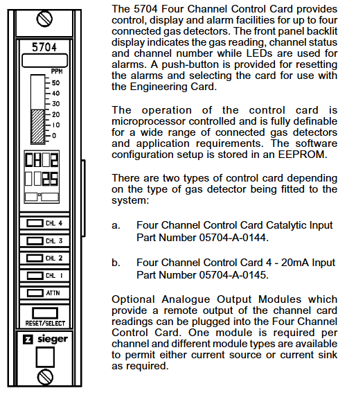
Four channel control card 05704-A-0144 (catalytic input)
05704-A-0145 (4-20mA input) sensor signal processing, concentration display, alarm logic judgment, 4 channels per card; The catalytic card supports constant current drive of 90-315mA; 4-20mA card supports 0-25mA signal measurement
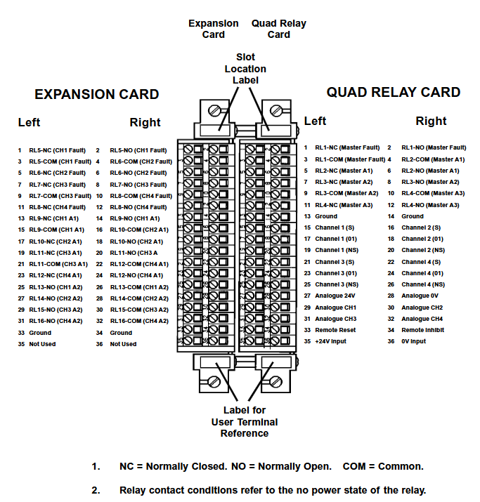
The four relay interface card 05704-A-0121 provides a wiring interface for sensors and control systems, providing four relay outputs (single pole double throw) with a rated current of 5A (110/250V AC or 32V DC) for relay contacts; Supports 2.5mm ² (14 AWG) wire connection
Relay expansion component 05704-A-0131 (interface card+expansion card) expands the number of relays to 16 (12 single pole double throw+4 single pole single throw), adapting to complex alarm linkage requirements and occupying 2 rack slots; Extra weight of 0.5kg, requires separate power supply
The core operating interface for system configuration, calibration, and diagnosis of engineering card 05701-A-0361 provides RS232 interface for connecting to PC or printer to support parameter adjustment (such as alarm threshold, sensor current), fault diagnosis, and maintenance record printing; Engineering key is required to unlock advanced features
DC input card 05701-A-0325 system power access and distribution, supports dual power input (main power+backup battery), provides overcurrent protection input voltage 18-32V DC; Built in 10A anti surge fuse; Support power diode isolation to avoid power conflicts
AC-DC power module 05701-A-0405 (16 channels)
05701-A-0406 (8-way) converts 85-264V AC to 24V DC system power supply, supports power upgrade (50W → 200W), 50W basic module can be expanded to 200W (16 way rack); Input frequency 47-440Hz, compatible with global power grid
2. Rack and cabinet configuration
Rack types: Four standard racks are available -19 inch 3U (rear wiring), 19 inch 6U (front wiring), half 19 inch 3U (rear wiring), half 19 inch 6U (front wiring), supporting both front and rear wiring methods to meet different on-site wiring requirements.
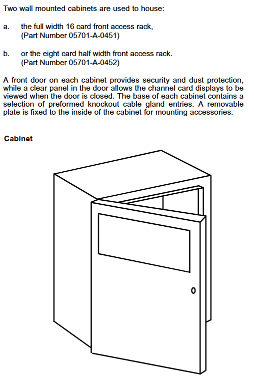
Cabinet accessories: Optional wall mounted cabinet (8/16 channels), made of cold-rolled steel plate material (RAL 7015 dark gray), providing multiple cable entry holes (M20/M25/PG11/PG16), with dust-proof and safety lock functions to protect internal modules from physical damage.
System operation and core functions
1. Basic operating procedures
(1) System startup and initialization
Power off inspection: Before starting, confirm that all control cards and interface cards have been correctly installed, the wiring is not loose, and the power supply voltage meets the requirements of 18-32V DC.
Step by step power on: First, connect the DC input card power supply and check that the green power light on the engineering card is always on (indicating that the power supply is normal); Insert the control cards one by one and observe that the "INHIBIT" light on each card lights up (the suppression period starts for about 30 seconds). After the suppression period ends, the light goes out and the system enters normal monitoring mode.
Sensor signal verification: Use the engineering card "BEAD mA" (catalytic card) or "SIGNAL" (4-20mA card) function to check if the sensor signal is normal (such as catalytic card bridge current of 200mA, 4-20mA card signal within normal range).
(2) Alarm and reset operations
Alarm recognition: Determine the alarm type through the control card LED light——
Red flashing: A1 (1 time/second), A2 (2 times/second), A3 (3 times/second) concentration alarm; STEL/LTEL alarm (1 second on/1 second off, slow flashing).
Yellow flashing: sensor malfunction, circuit malfunction; Yellow constantly on: Channel suppressed (manual/remote suppression).
Reset operation:
Normal reset: Short press the "RESET/SET" button on the control card to clear inactive lock alarms, fault prompts, and peak displays.
Extended reset: Long press the "RESET/SET" button for 5 seconds to clear the maximum/minimum concentration record, STEL/LTEL timer, and reset the delay relay.
2. Engineering calibration and maintenance
(1) Key calibration steps (unlocked with engineering key)
Zero point calibration (ZERO):
Place the sensor in a clean environment without target gas (such as fresh air) and wait for the signal to stabilize (the control card displays the "Stable" icon).
Select the target channel, press the "ZERO" button on the engineering card, and the system will automatically set the current signal to zero. After calibration, the channel suppression needs to be released.
Range Calibration (SPAN):
Introduce a standard gas of known concentration (recommended concentration ≥ 40% of full range) and wait for the sensor signal to stabilize.
Press the "SPAN" button on the engineering card to adjust the numerical display to the standard gas concentration. After confirmation, the system saves the range parameters and updates the calibration date.
First range calibration (1st SPAN): For new catalytic sensors, record the initial sensitivity for subsequent sensor life monitoring (triggering a "life expiration" alarm when the sensitivity drops to 50% of the initial value).
(2) Key points for regular maintenance
Monthly inspection: Clean the surface dust of the module, check the tightness of the wiring terminals, and verify whether the alarm relay operates normally.
Annual calibration: Perform zero and range calibration according to sensor type (catalytic/4-20mA), check the accuracy of the engineering card clock, and print maintenance records (via RS232 printer).
Sensor replacement: It is recommended to replace catalytic sensors every 1-2 years, and 4-20mA sensors should be replaced according to the manufacturer's requirements. After replacement, the "1st SPAN" calibration needs to be performed again.

System configuration and scalability
1. Flexible configuration options
Alarm logic configuration: supports multiple alarm modes——
Independent alarm: Single channel alarm does not affect other channels;
Zoned alarm: Any channel alarm within the designated area triggers the overall alarm of the zone;
Voted alarm: Multiple channels alarm simultaneously (such as 2/3 channel alarm) to trigger the total alarm, avoiding single sensor false alarms;
Update alarm: Even if there are unreset alarms, new alarms can still trigger prompts to avoid omissions.
Output configuration:
Relay output: can be configured as "normal power on" (power off trigger) or "normal power off" (power on trigger), supporting a switching time of 13-48ms;
Analog output: Each channel can choose 0-20mA or 4-20mA isolated output, used to connect PLC, DCS and other systems to transmit real-time concentration data.
2. Expansion and customization capabilities
Hardware expansion: Increase the number of relays by adding relay expansion cards (05704-A-0131); Upgrade the system power from 50W to 200W by stacking AC-DC power modules (05701-A-0440), supporting more channels.
Software and Communication Expansion:
Engineering software: Configure system parameters (such as alarm thresholds and sensor types) on PC through "Engineering Interface Software", and support data log storage;
Communication module: optional Modbus interface module (RS232/RS422/485), realizing digital communication with the upper computer (such as SCADA system), only used for data visualization, prohibited for safety related control;
Event printing module: Record alarm, fault events, and timestamps for easy traceability and compliance auditing.
Fault diagnosis and common problems
1. Fault codes and troubleshooting
The system displays the "ERxx" fault code through the control card LCD, and the core fault types and handling methods are as follows:
Meaning of fault code, possible causes, handling suggestions
ER97 EEPROM malfunction (configuration data lost) Control card storage chip damaged Replace control card
ER87 signal out of range (above configuration limit), sensor short circuit, high gas concentration. Check the sensor circuit and confirm the gas concentration on site
ER88 signal under range (below the lower limit of configuration) sensor open circuit, wire breakage check sensor wiring, replace faulty sensor
ER83 catalytic sensor bridge current fault sensor aging, excessive line resistance check line resistance (≤ 40 Ω), replace sensor
ER82 sensor lifespan expires, catalytic sensor sensitivity drops below 50%, replace sensor immediately
2. Common operational issues
Engineering card unresponsive: Check the DC input card power supply (18-32V DC) and fuse (10A). If the power supply is normal, try restarting the system;
Alarm not triggered: Confirm that the channel is not suppressed (INHIBIT light off), check if the alarm threshold configuration is correct, and verify the relay wiring;
Analog output abnormality: Check if the analog module (04200-A-0145/0146) is securely plugged in and confirm that the output type (current source/current sink) matches the external device.
Technical parameters and ordering information
1. Core technical parameters
Environmental adaptability: working temperature 0-55 ℃ (ATEX certification system starts at 0 ℃), storage temperature -25-85 ℃, relative humidity 0-90% (no condensation), altitude ≤ 5000m.
Electrical parameters: System power supply 18-32V DC; Control card power consumption 8.3-12.8W (depending on type); Relay contact capacity 5A (AC/DC).
Display and accuracy: Control card LCD display (4-character number+25 segment analog strip), concentration measurement accuracy ± 1% of full range, alarm threshold resolution 1% of full range.
2. Main ordering models
Example description of component type and model
Control card 05704-A-0144 four channel catalytic combustion sensor input card
Control card 05704-A-0145 four channel 4-20mA sensor input card
Relay Interface Card 05704-A-0121 Four Relay Interface Card (Basic Version)
Engineering Card 05701-A-0361 System Configuration and Diagnostic Card
AC-DC power supply 05701-A-0405 16 channel 50W power module (upgradable to 200W)
Cabinet 05701-A-0451 8-way wall mounted cabinet (cold-rolled steel plate)
- OMRON
- ABB
- General Electric
- EMERSON
- Honeywell
- HIMA
- ALSTOM
- Rolls-Royce
- MOTOROLA
- Rockwell
- Siemens
- Woodward
- YOKOGAWA
- FOXBORO
- KOLLMORGEN
- MOOG
- KB
- YAMAHA
- BENDER
- TEKTRONIX
- Westinghouse
- AMAT
- AB
- XYCOM
- Yaskawa
- B&R
- Schneider
- KONGSBERG
- NI
- WATLOW
- ProSoft
- SEW
- ADVANCED
- Reliance
- TRICONEX
- METSO
- MAN
- Advantest
- STUDER
- DANAHER MOTION
- Bently
- Galil
- EATON
- MOLEX
- DEIF
- B&W
- ZYGO
- Aerotech
- DANFOSS
- Beijer
- Moxa
- Rexroth
- Johnson
- WAGO
- TOSHIBA
- BMCM
- SMC
- HITACHI
- HIRSCHMANN
- Application field
- XP POWER
- CTI
- TRICON
- STOBER
- Thinklogical
- Horner Automation
- Meggitt
- Fanuc
- Baldor
- SHINKAWA
- Other Brands
- UniOP
- KUKA
- Iba
- Beckhoff
-
 OMRON B7AM-8B16 I/O Terminal Block
 -
 Fanuc A06B-6110-H026 Power Supply Module
 -
 Schneider TSXETG3021 Ethernet Gateway
 -
 OMRON CS1W-CLK21-V1 Controller Link Unit
 -
 NP1W6406T-Z704 PLC I/O Module
 -
 OMRON CJ1W-DA08C Analog Output Module
 -
 Yaskawa 3G3HV-A4022-CE AC Drive
 -
 OMRON NB7W-TW01B CP1L-EL20DR-D Power Panel
 -
 OMRON C500-NC103-E Position Control Unit
 -
 Steag Hamatech PLC DCS Servo Control System
 -
 Siemens 6SN1123-1AA00-0DA1 Power Supply Module
 -
 GE IC693CHS391H CPU & AD693CMM301A PLC Module
 -
 Siemens 6FC5303-0AF23-1AA1 PLC Control Panel
 -
 Square D CM4000T PowerLogic Circuit Monitor J1 F16
 -
 Siemens 6FX5002-5DG10-1BA0 MOTION-CONNECT 500 Cable
 -
 Schmersal SRB324ST 101195504 Safety Relay 24V
 -
 Mitsubishi 15050-PR02A PLC Circuit Board Module
 -
 OMRON CQM1-AD041 Analog Input PLC Module
 -
 Beckhoff EL5042 EtherCAT PLC Terminal Module
 -
 OMRON C200HW-MC402-E Motion Control Unit
 -
 C36TC0UA1100 Industrial Temperature Controller
 -
 NL8048BC24 12 Industrial Control LCD Module
 -
 OMRON R88D Servo Drive and Motor System
 -
 OMRON CS1W CLK21 V1 Controller Link Module
 -
 OMRON YASKAWA R7M A20030 S1 D Servo Motor
 -
 SIEMENS 6AV2128 3KB06 0AX1 Unified Comfort Panel
 -
 Schneider Electric METSEPM8240 PowerLogic Meter
 -
 Advanced AMCI 1PLC 1 31F Programmable Limit Switch
 -
 ABB PM582 ETH Programmable Logic Processor
 -
 SIEMENS 6FC5110 0CB01 0AA0 CPU Control Board
 -
 Schleicher P03GS13A CPU Module
 -
 Siemens 6SN1123-1AA00-0BA1 Power Module
 -
 Mitsubishi A1S61PN Power Supply Module
 -
 Yaskawa CPS-IONB DC Power Supply Module
 -
 Siemens 6ES7215-2BD00 CPU 215-2
 -
 Mitsubishi A2ACPU MELSEC PLC System Kit
 -
 ProSoft 3150-MCM Communication Module
 -
 Mitsubishi OSE104ET Incremental Encoder
 -
 OMRON CJ1W-AD081-V1 Analog Input Module
 -
 Broadcom BCM5464A1KRB Quad Port Ethernet IC
 -
 Modicon M221-24IO TM221C24 PLC 24 PNP Transistor
 -
 Allen-Bradley 1321-3R160-B Line Reactor 3R160B
 -
 Beckhoff CX1020-0012 Embedded PLC Module Specs
 -
 Turck BL20-PF-24VDC-D Power Feed Module Specs
 -
 Siemens 6SY7000-0AC37 Power Supply Module
 -
 Yaskawa SGDH-10DE-OY 1kW 400V Servo Drive Specs
 -
 Omron 3G3SV-BB015-E 1.5kW 220V VFD Specs
 -
 Uni-Pro CPU91-PLC J 23.020167X Processor Module
 -
 PASABAN MTC-3044 PLC Rack Power Supply 4835-A
 -
 XYCOM 3015T Operator Interface Panel BIN4.4.4
 -
 OMRON CJ1W-MD261 Mixed I/O Module
 -
 Omron NJ301-1100 PLC CPU eCat EIP Specs
 -
 Omron F500-C15-ETN Vision System PLC Module
 -
 Modicon M241-24IO TM/T2UK PLC with Ethernet
 -
 SIXNET YS-800-001 RTU PLC Module
 -
 BEMAC UST-202-D Interface Board 1307D V08B2
 -
 Yaskawa JANCD-MMOIC-02 Drive Circuit Board
 -
 ABB 3BSE005028R1 SDCS-COM-1 Comm Board
 -
 Omron 3G3MX2-A4110 A4150 Inverter Drives Specs
 -
 KEYENCE CA-E100 PLC Module
 -
 GE IC693ALG223-GB Analog Input Module Specs
 -
 ABB BAILEY IMMFP01 Multi Function Processor System
 -
 SIEMENS 6FC5372 0AA00 0AA1 NCU 7202 Controller
 -
Modicon TM241CE4 40I O Transistor Programmable Controller
-
 SIEMENS 6ES7 315 2EH13 0AB0 CPU 3152 PN DP
 -
 NORIS A1 91 PCB Card Rack Module System
 -
 SIEMENS 6ES7 313 5BE01 0AB0 Compact CPU
 -
 SCHNEIDER ELECTRIC S144B MICROLOGIC 60A Trip Unit
 -
 CNI PLC269 v3 Control Module Board Rev H
 -
ABB BAILEY IIMCP02 Processor Module
-
 OMRON NT20S ST121 EV3 Operator Interface Terminal
 -
 OMRON NS-CA001 Video Input Unit
 -
 GE Fanuc IC695CHS012 RX3i Backplane
 -
 Allen Bradley 2711E-K14C6 PanelView 1400e Terminal
 -
 Siemens Sinamics CCB 10000432.71 Power Cell
 -
 Siemens 6SL3210-1SE21-8UA0 Power Module PM340
 -
 Yaskawa CIMR-F7A20P4 AC Drive
 -
 Beckhoff EP1918-0002 EtherCAT Box I/O Module
 -
 OMRON CQM1-TC001 Temperature Control Module
 -
 GE Fanuc SGHA36AT0400 Industrial Contactor
 -
 OMRON NJ501-1500 PLC Machine Automation Controller
 -
 Mitsubishi MAZAK QX084 Power Supply MELDAS 500 CNC
 -
 B&R 0AC808.9 PLC Automation Module
 -
 OMRON CP1H-XA40DT1-D PLC Module
 -
 G&W Electric PLC15 5111 011 15kV Capnut Assembly
 -
 GE DS200SLCCG3AGH PCB Circuit Board
 -
 Siemens SINUMERIK 6FC3981-4FD PLC Extension
 -
 OMRON F300-DC I/O Image Processing Unit
 -
 FANUC A06B-0314-B002 AC Servo Motor
 -
 GC-S84 Programmable Controller Logic Module
 -
 PASABAN MONTELEC MTC3001-DC Drive Control PLC
 -
 Allen Bradley 100E460EJ11 Auxiliary Contactor
 -
 Bosch Rexroth 1070075337-101 Card Parameters
 -
 HMS Anybus AB7646-F Gateway Specifications
 -
 Bosch 062633-303401 CNC Servo PLC Card
 -
 TI 500-5023 Series PLC Power Supply
 -
 Siemens C98043-A7002-L1-12 Circuit Board
 -
 Omron E5CC-RX3A5M-000 Controller
 -
 CN-8032-L Profinet Network Adapter Module
 -
 Siemens 3TK2804-0BB4 Safety Relay Details
 -
 Toledo TTLM-2-1M I/O Load Module
 -
 NORIS A1-91 PLC Rack Board Specifications
 -
 Mitsubishi A3ACPUR21 MELSEC PLC CPU Module
 -
 Beckhoff EP7041‑3002 EtherCAT Box Digital Input Module
 -
 REER EOS2E 1053 EOS2R 1053 Safety Light Curtain
 -
 Mitsubishi Q80BD-J71BR11 MELSECNET/H Interface Board
 -
 Omron 3G3IV-B4220-EV2 VFD 400V 22kW
 -
 Allen-Bradley 96844671 1785-LT3 PLC-5/12 Processor Module
 -
 Pasaban MTC3001-DC Drive Control PLC Module
 -
 Omron CJ1M-CPU11 V4.0 PLC CPU Module
 -
 ABB CM579-PNIO B3 Communication Module
 -
 B&R X20 AI 4221 Analog Module
 -
 Siemens 6SY7000-0AC80 PLC Module
 -
 GE 531X300CCHAFM5 Control Card
 -
 AB 810-A15C Inverse Time Relay
 -
 WITTENSTEIN LP120X-MF2-20 Planetary Gear
 -
 Mitsubishi Kakoki E-01B-4130 PLC I/O Modules
 -
 ABB DSQC643 Safety Control Board
 -
 Siemens G26004-A2105-P100-2 PCB
 -
 OMRON F350-C10E Image Processing Unit
 -
 FUJI UG430H-TS1 HMI Touch Panel
 -
 Westronics CB100188-01 Rev F Board
 -
 Siemens 7MH4900-3AA01 Weighing Module
 -
 Gilbert & Nash Tracker 2000 Control Cabinet
 -
 OMRON CJ1M-CPU22 CPU Unit
 -
 OMRON F3SJ-E0625P25 Light Curtain
 -
 Siemens 3VA2340-5HL32-0AA0 Breaker
 -
 Mitsubishi Melsec A61P A2NCPU PLC System


