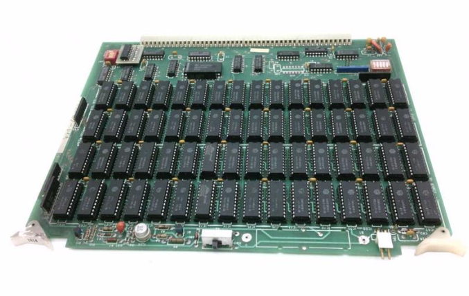
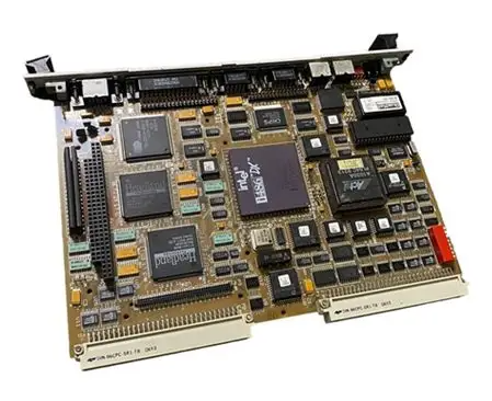
GE VMIVME-3125 Analog Input Board
GE VMIVME-3125 Analog Input Board
Product Overview
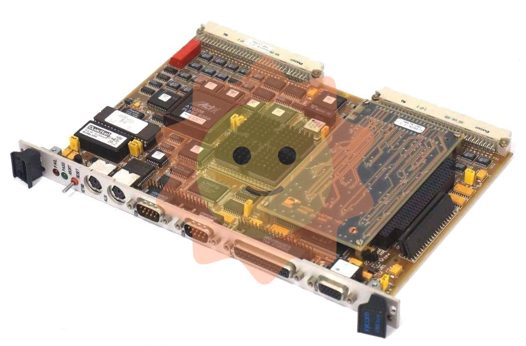
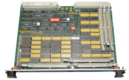
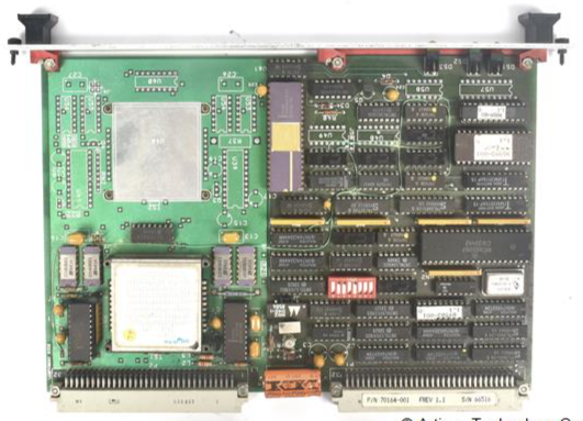
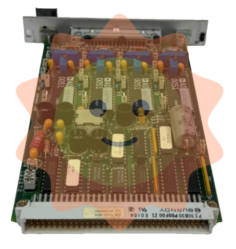
VMIVME-3125 is a flexible and low-cost analog input board that adopts the VMEbus 6U single height format and provides 16 differential or 32 single ended analog input channels. The channels are digitized using a 12 bit resolution analog-to-digital converter (ADC). This board does not require software settings, and will automatically start scanning all input channels after power on or system reset. The converted data is stored in dual port memory and can be accessed immediately through VMEbus. It also has a built-in self-test (BIT) function, and the input voltage range and gain can be programmed by the user through jumper wires. The VMEbus base address and access mode can be fully selected.
Core Features
16 differential or 32 single ended analog input channels.
1 12 bit A/D converter with built-in tracking and holding function.
All inputs are automatically scanned at a total rate of 40 kHz.
Scanning can begin without software initialization.
The input range is from ± 50 mV to ± 10 VDC.
Input overvoltage protection, analog input is low-pass filtered at 50 kHz, and an optional 40 Hz low-pass filter sub board can be added.
Supports discrete or large-scale terminated cables.
Input pull-down resistor to prevent input floating.
Supports both online and offline built-in testing (BIT).
The programmable gain of the jumper is x1, x10, x100.
The optional A/D range is ± 5 VDC, ± 10 VDC, and 0 to 10 VDC.
Data access methods: D16, D08 (EO), D08 (O).
Front panel LED indicator light.
1000 VDC isolation between analog ground and digital ground.
Optional 0-20, 4-20, and 5-25 mA current input ranges.
Working principle
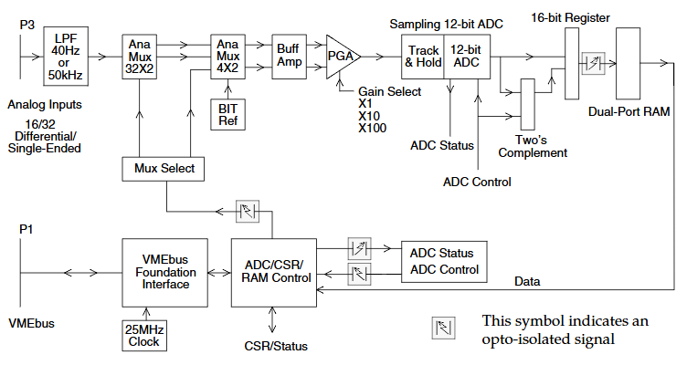
Functional components: mainly including VMEbus interface, analog-to-digital converter (ADC) and control logic, analog input multiplexing, gain and conversion, BIT voltage reference and multiplexer, board ID register and other functional parts.
VMEbus interface: Communication registers are mapped to 64 16 bit words (128 bytes) in memory, which can be located on any 128 byte boundary within the VMEbus short I/O space and can be configured to respond to short monitoring or short non privileged data access.
Analog to digital conversion control and timing: There are two operating modes, namely continuous scanning of all 16 or 32 analog input channels, and stopping scanning and locking to a single channel. Using a 12 bit ADC with a conversion time of 8.5 μ sec, the channel acquisition cycle is once every 25 μ sec, and the total scanning rate is 40 kHz. The ADC's built-in tracking and holding device can prevent erroneous readings from signals that change during the conversion cycle.
Built in Test Reference: Equipped with programmable precision voltage reference for board built-in testing (BIT). When selected, the BIT voltage is fed to the ADC through a programmable gain amplifier, bypassing the external analog input on channel 0. Users can enable BIT during initial board installation or real-time system self diagnosis.
Analog Input: The front panel connector provides 16 differential or 32 single ended analog inputs. It is recommended to use differential mode to reduce noise and improve common mode rejection ratio. Unused inputs should be grounded, and the low end of the differential input on the board has an internal 22 M Ω pull-down resistor.
Low pass filter: Provides a passive single pole low-pass input filter with a normal -3 dB cut-off frequency of 50 kHz, and can also be configured with an additional sub board to provide a low-pass filter with a cut-off frequency of 40 Hz.
Input multiplexer: There are two levels of analog multiplexing, with each of the 32 inputs selected through one of the four 8x1 first level analog input multiplexers. The second level multiplexer is configured as a 4x2 board, and one or two of the first level output signals are selected to provide single ended or differential operation mode. BIT reference voltage can also be selected.
Programmable gain instrumentation amplifier: After selecting the input channel and passing through the input multiplexer, it enters the programmable gain amplifier as a differential input. The differential amplifier suppresses common mode noise and delivers the scaled single ended output to the ADC. The hardware can jumper the gain to 1, 10, and 100.
Channel sequencer and dual port RAM memory: typically run in scan mode, starting conversion immediately after power on or reset. After A/D conversion is completed, the dual port control logic retrieves the conversion data and stores it in the corresponding dual port register of the channel. The channel counter increments and selects the next channel to be multiplexed to the ADC. After all input channels are converted and stored, the channel counter resets and starts the channel scanning sequence again. The channel sequencer can be stopped at the current address by the stop auto scan bit in the control/status register.
Board ID Register: The first position of the VMIVME-3125 register group is the read-only board ID register, with a value of $37, used for general system software to automatically determine the installed board.
- ABB
- General Electric
- EMERSON
- Honeywell
- HIMA
- ALSTOM
- Rolls-Royce
- MOTOROLA
- Rockwell
- Siemens
- Woodward
- YOKOGAWA
- FOXBORO
- KOLLMORGEN
- MOOG
- KB
- YAMAHA
- BENDER
- TEKTRONIX
- Westinghouse
- AMAT
- AB
- XYCOM
- Yaskawa
- B&R
- Schneider
- Kongsberg
- NI
- WATLOW
- ProSoft
- SEW
- ADVANCED
- Reliance
- TRICONEX
- METSO
- MAN
- Advantest
- STUDER
- KONGSBERG
- DANAHER MOTION
- Bently
- Galil
- EATON
- MOLEX
- Triconex
- DEIF
- B&W
- ZYGO
- Aerotech
- DANFOSS
- Beijer
- Moxa
- Rexroth
- Johnson
- WAGO
- TOSHIBA
- BMCM
- SMC
- HITACHI
- HIRSCHMANN
- Application field
- XP POWER
- CTI
- TRICON
- STOBER
- Thinklogical
- Horner Automation
- Meggitt
- Fanuc
- Baldor


