
BENDER WR70x175S (P)... WR200x500S (P) rectangular measuring current transformer
BENDER WR70x175S (P)... WR200x500S (P) rectangular measuring current transformer
Product Overview
(1) Core positioning and adaptation scenarios
Product Name WR70x175S (P)... WR200x500S (P) Rectangular Measuring Current Transformer
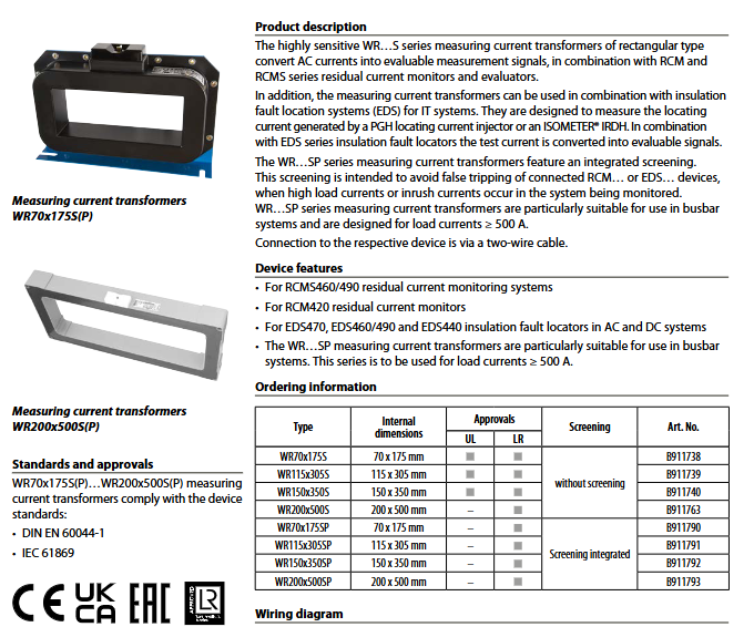
Core application: 1. Cooperate with residual current monitoring systems such as RCMS460/490 and RCM420 to convert AC current into assessable signals;
2. Cooperate with insulation fault location systems such as EDS470/460/490/440 (IT system) to collect positioning currents generated by PGH positioning current injectors or IRDH series insulation monitoring instruments
Suitable for industrial electrical systems and busbar systems, the SP series is particularly suitable for scenarios with load currents ≥ 500A, which can avoid false triggering caused by high load currents or surge currents
(2) Compliance and Certification
Following standards: DIN EN 60044-1 (General Standard for Current Transformers), IEC 61869 (Standard for Power Transformers)
Safety level: The flame retardant rating of the shell is UL94 V-0, the protection level of the internal components is IP40, and the protection level of the terminals is IP20
Product Classification and Core Features
(1) Series classification
Examples of applicable scenario models for the core features of the series
S series without integrated shielding for conventional load current scenarios WR70x175S, WR200x500S
SP series with integrated shielded busbar system, load current ≥ 500A scenario, anti misoperation WR115x305SP, WR150x350SP
(2) Core functions and advantages
Signal conversion: Fixed 600:1 rated transformation ratio, converts the primary side current (≥ 10mA) into a secondary side assessable signal, providing accurate data for monitoring/positioning systems.
Overvoltage protection: The secondary side is equipped with a suppression diode (P6KE6V8CP) to ensure equipment safety.
Flexible installation: Supports installation at any position, and wire connections are compatible with multiple specifications (rigid/flexible conductors).
Anti interference design: The integrated shielding of the SP series can resist the interference of high load current and surge current, avoiding false triggering of connected devices.
Key technical parameters
(1) Electrical parameters
Maximum system voltage AC 720 V
Rated impulse withstand voltage 3 kV
Rated transformation ratio 600/1
Rated load 180 Ω
Rated primary current ≤ 10 A (100 A), minimum ≥ 10 mA
Rated nominal power 50 mVA
Rated frequency 50... 400 Hz
Internal resistance 5... 8 Ω
Accuracy level 5
Rated continuous thermal current of 100 A
Rated short-time thermoelectric current 14 kA/1 s
Rated dynamic current 35 kA/30 ms
(2) Environmental and mechanical parameters
Category specific specifications
Working environment temperature -10...+50 ℃
Storage environment temperature -40...+70 ℃
Climate grade DIN IEC 60721-3-3 (3K22)
Impact resistance performance during operation at 15 g/11 ms (IEC 60068-2-27)
Vibration resistance performance during operation at 1 g/10... 150 Hz (IEC 60068-2-6)
Protection level: Internal components IP40, terminals IP20
Install and fix M5 screw installation
Shell material flame retardant grade UL94 V-0
(3) Size and weight
Model Internal dimensions (A × B, mm) Weight
WR70x175S(P) 70×175 2200 g
WR115x305S(P) 115×305 4500 g
WR150x350S(P) 150×350 5900 g
WR200x500S(P) 200×500 11500 g
(4) Connection parameters
Connection type specification requirements
Terminal type: screw terminal
Conductor adaptation rigidity 0.2... 4mm ², flexibility 0.2... 2.5mm ², flexible conductor with/without plastic collar 0.25... 2.5mm ² (AWG 24... 12)
The cable requires a single core wire of ≥ 0.75mm ² (0... 1m); Stranded single core wire ≥ 0.75mm ² (0... 10m); Shielded cable ≥ 0.6mm ² (0... 40m), recommended J-Y (St) Y 2 × 0.6mm ² (shielding layer single end connected to PE)
Installation and usage specifications
(1) Core installation requirements
Prohibited conductors to pass through: shielded cables, PE conductors, and low resistance conductor circuits to avoid affecting measurement accuracy.
Wire direction and position: The wire needs to enter from the P1 (K, yellow identification) side and exit from the P2 (L, gray identification) side, and all current carrying wires need to pass through the transformer; The wire should be aligned with the center of the transformer, and the bending radius should follow the manufacturer's specifications. The 90 ° bending distance should not be less than twice the height of the transformer.
Installation position: It can be installed in any direction to ensure a firm and secure fixation without looseness.
(2) Wiring precautions
Shielded cables need to be grounded at one end (connected to PE), with a maximum connection distance of 40m. If the distance exceeds 40m, compliant shielded cables must be used to ensure signal transmission.
The wiring terminals need to be tightened to avoid signal distortion caused by poor contact.
Order Information
Model Internal dimensions (mm) Shielding characteristics Order number
WR70x175S 70 × 175 without B911738
WR115x305S 115 × 305 without B911739
WR150x350S 150 × 350 without B911740
WR200x500S 200 × 500 without B911763
WR70x175SP 70 × 175 integrated shielding B911790
- OMRON
- ABB
- General Electric
- EMERSON
- Honeywell
- HIMA
- ALSTOM
- Rolls-Royce
- MOTOROLA
- Rockwell
- Siemens
- Woodward
- YOKOGAWA
- FOXBORO
- KOLLMORGEN
- MOOG
- KB
- YAMAHA
- BENDER
- TEKTRONIX
- Westinghouse
- AMAT
- AB
- XYCOM
- Yaskawa
- B&R
- Schneider
- KONGSBERG
- NI
- WATLOW
- ProSoft
- SEW
- ADVANCED
- Reliance
- TRICONEX
- METSO
- MAN
- Advantest
- STUDER
- DANAHER MOTION
- Bently
- Galil
- EATON
- MOLEX
- DEIF
- B&W
- ZYGO
- Aerotech
- DANFOSS
- Beijer
- Moxa
- Rexroth
- Johnson
- WAGO
- TOSHIBA
- BMCM
- SMC
- HITACHI
- HIRSCHMANN
- Application field
- XP POWER
- CTI
- TRICON
- STOBER
- Thinklogical
- Horner Automation
- Meggitt
- Fanuc
- Baldor
- SHINKAWA
- Other Brands
- UniOP
- KUKA
- Iba
- Beckhoff
-
 OMRON C60H C6DR DE V1 Sysmac PLC
 -
 MITSUBISHI ELECTRIC A2ACPU21 S1 CPU Module
 -
 ABB BAILEY INNPM12 Network Process Module
 -
 HONEYWELL 620 0073C IPC PLC Module
 -
 Mitsubishi 15050 PR02B PLC Circuit Board
 -
 SIEMENS 6SY7000 0AC37 Drive Control Module
 -
 OMRON TJ2 ECT16 Traxial EtherCAT Controller
 -
 GE Fanuc IC698PSD300D Power Supply Module
 -
 Texas Instruments Series 505 16 Position Base
 -
 OMRON YASKAWA SGDH 10DE OY Servo Drive
 -
 Allen‑Bradley 440G-MT Safety Interlock Switch Specs
 -
 Rubycon PD27A 24V 8A Power Supply Module
 -
 SK-H1-GDB1-F11D PLC Gate Driver Board Kit
 -
 VIPA 441-4UA14 451-4UA14 PLC Module Rack
 -
 Mitsubishi FX5U-80MT ESS PLC Controller Specs
 -
 Mitsubishi Q64TCRTN Temperature PLC Module
 -
 GE 1C31170G Rev10 PLC Circuit Board Module
 -
 Schneider TWDLMDA40DTK PLC Controller Module
 -
 Omron FQM1-MMA22 Motion Control Module Specs
 -
 OMRON CJ1W-NCF71 Position Control Unit Specs
 -
 Schneider TSXETY4103 Ethernet Module
 -
 Mitsubishi Q12PHCPU Process CPU
 -
 Yaskawa 3G3HV-A4022-CE AC Drive
 -
 Cincinnati Milacron 3-533-0669G Temperature Control Board
 -
 Allen Bradley 20AC030A3AYNANC0 PowerFlex 70 Drive
 -
 Siemens 6ES7314-6BG03-0AB0 CPU 314C-2 DP
 -
 Carrier 17EX54007903 PLC Module
 -
 OMRON CS1W-V600C12 ID Controller Module
 -
 Honeywell 51402755-100 PCB Card
 -
 Heidenhain ECN 113 Rotary Encoder
 -
 OMRON B7AM-8B16 I/O Terminal Block
 -
 Fanuc A06B-6110-H026 Power Supply Module
 -
 Schneider TSXETG3021 Ethernet Gateway
 -
 OMRON CS1W-CLK21-V1 Controller Link Unit
 -
 NP1W6406T-Z704 PLC I/O Module
 -
 OMRON CJ1W-DA08C Analog Output Module
 -
 Yaskawa 3G3HV-A4022-CE AC Drive
 -
 OMRON NB7W-TW01B CP1L-EL20DR-D Power Panel
 -
 OMRON C500-NC103-E Position Control Unit
 -
 Steag Hamatech PLC DCS Servo Control System
 -
 Siemens 6SN1123-1AA00-0DA1 Power Supply Module
 -
 GE IC693CHS391H CPU & AD693CMM301A PLC Module
 -
 Siemens 6FC5303-0AF23-1AA1 PLC Control Panel
 -
 Square D CM4000T PowerLogic Circuit Monitor J1 F16
 -
 Siemens 6FX5002-5DG10-1BA0 MOTION-CONNECT 500 Cable
 -
 Schmersal SRB324ST 101195504 Safety Relay 24V
 -
 Mitsubishi 15050-PR02A PLC Circuit Board Module
 -
 OMRON CQM1-AD041 Analog Input PLC Module
 -
 Beckhoff EL5042 EtherCAT PLC Terminal Module
 -
 OMRON C200HW-MC402-E Motion Control Unit
 -
 C36TC0UA1100 Industrial Temperature Controller
 -
 NL8048BC24 12 Industrial Control LCD Module
 -
 OMRON R88D Servo Drive and Motor System
 -
 OMRON CS1W CLK21 V1 Controller Link Module
 -
 OMRON YASKAWA R7M A20030 S1 D Servo Motor
 -
 SIEMENS 6AV2128 3KB06 0AX1 Unified Comfort Panel
 -
 Schneider Electric METSEPM8240 PowerLogic Meter
 -
 Advanced AMCI 1PLC 1 31F Programmable Limit Switch
 -
 ABB PM582 ETH Programmable Logic Processor
 -
 SIEMENS 6FC5110 0CB01 0AA0 CPU Control Board
 -
 Schleicher P03GS13A CPU Module
 -
 Siemens 6SN1123-1AA00-0BA1 Power Module
 -
 Mitsubishi A1S61PN Power Supply Module
 -
 Yaskawa CPS-IONB DC Power Supply Module
 -
 Siemens 6ES7215-2BD00 CPU 215-2
 -
 Mitsubishi A2ACPU MELSEC PLC System Kit
 -
 ProSoft 3150-MCM Communication Module
 -
 Mitsubishi OSE104ET Incremental Encoder
 -
 OMRON CJ1W-AD081-V1 Analog Input Module
 -
 Broadcom BCM5464A1KRB Quad Port Ethernet IC
 -
 Modicon M221-24IO TM221C24 PLC 24 PNP Transistor
 -
 Allen-Bradley 1321-3R160-B Line Reactor 3R160B
 -
 Beckhoff CX1020-0012 Embedded PLC Module Specs
 -
 Turck BL20-PF-24VDC-D Power Feed Module Specs
 -
 Siemens 6SY7000-0AC37 Power Supply Module
 -
 Yaskawa SGDH-10DE-OY 1kW 400V Servo Drive Specs
 -
 Omron 3G3SV-BB015-E 1.5kW 220V VFD Specs
 -
 Uni-Pro CPU91-PLC J 23.020167X Processor Module
 -
 PASABAN MTC-3044 PLC Rack Power Supply 4835-A
 -
 XYCOM 3015T Operator Interface Panel BIN4.4.4
 -
 OMRON CJ1W-MD261 Mixed I/O Module
 -
 Omron NJ301-1100 PLC CPU eCat EIP Specs
 -
 Omron F500-C15-ETN Vision System PLC Module
 -
 Modicon M241-24IO TM/T2UK PLC with Ethernet
 -
 SIXNET YS-800-001 RTU PLC Module
 -
 BEMAC UST-202-D Interface Board 1307D V08B2
 -
 Yaskawa JANCD-MMOIC-02 Drive Circuit Board
 -
 ABB 3BSE005028R1 SDCS-COM-1 Comm Board
 -
 Omron 3G3MX2-A4110 A4150 Inverter Drives Specs
 -
 KEYENCE CA-E100 PLC Module
 -
 GE IC693ALG223-GB Analog Input Module Specs
 -
 ABB BAILEY IMMFP01 Multi Function Processor System
 -
 SIEMENS 6FC5372 0AA00 0AA1 NCU 7202 Controller
 -
Modicon TM241CE4 40I O Transistor Programmable Controller
-
 SIEMENS 6ES7 315 2EH13 0AB0 CPU 3152 PN DP
 -
 NORIS A1 91 PCB Card Rack Module System
 -
 SIEMENS 6ES7 313 5BE01 0AB0 Compact CPU
 -
 SCHNEIDER ELECTRIC S144B MICROLOGIC 60A Trip Unit
 -
 CNI PLC269 v3 Control Module Board Rev H
 -
ABB BAILEY IIMCP02 Processor Module
-
 OMRON NT20S ST121 EV3 Operator Interface Terminal
 -
 OMRON NS-CA001 Video Input Unit
 -
 GE Fanuc IC695CHS012 RX3i Backplane
 -
 Allen Bradley 2711E-K14C6 PanelView 1400e Terminal
 -
 Siemens Sinamics CCB 10000432.71 Power Cell
 -
 Siemens 6SL3210-1SE21-8UA0 Power Module PM340
 -
 Yaskawa CIMR-F7A20P4 AC Drive
 -
 Beckhoff EP1918-0002 EtherCAT Box I/O Module
 -
 OMRON CQM1-TC001 Temperature Control Module
 -
 GE Fanuc SGHA36AT0400 Industrial Contactor
 -
 OMRON NJ501-1500 PLC Machine Automation Controller
 -
 Mitsubishi MAZAK QX084 Power Supply MELDAS 500 CNC
 -
 B&R 0AC808.9 PLC Automation Module
 -
 OMRON CP1H-XA40DT1-D PLC Module
 -
 G&W Electric PLC15 5111 011 15kV Capnut Assembly
 -
 GE DS200SLCCG3AGH PCB Circuit Board
 -
 Siemens SINUMERIK 6FC3981-4FD PLC Extension
 -
 OMRON F300-DC I/O Image Processing Unit
 -
 FANUC A06B-0314-B002 AC Servo Motor
 -
 GC-S84 Programmable Controller Logic Module
 -
 PASABAN MONTELEC MTC3001-DC Drive Control PLC
 -
 Allen Bradley 100E460EJ11 Auxiliary Contactor
 -
 Bosch Rexroth 1070075337-101 Card Parameters
 -
 HMS Anybus AB7646-F Gateway Specifications
 -
 Bosch 062633-303401 CNC Servo PLC Card
 -
 TI 500-5023 Series PLC Power Supply
 -
 Siemens C98043-A7002-L1-12 Circuit Board
 -
 Omron E5CC-RX3A5M-000 Controller


