Watlow EZ-ZONE ® RMA (Access) module
Record parameters:
Cycle: Adjustable from 1-3600 seconds (default 10 seconds), supports event triggering (such as alarms, digital input signals).
Full storage strategy: "Stop" or "Overwrite" (overwrite older data, leaving 1.5MB of free space).
Timestamp: Dependent on Real Time Clock (RTC), supports HH: MM/HH: MM: SS time format, MM/DD/YYYY/DD/MM/YYYY date format.
(2) Configuration steps (taking RUI operation as an example)
Go to Setup → Data Logging Menu, set Period and Full Action.
Enter the Log Point Menu and configure the Source Function (data source, such as Analog Input), Source Zone (module address), and Display Precision (recording accuracy, such as 0.1/0.01) for each log point.
Startup record: The log file is automatically named by date/time (such as LOG_20241001_1430. csv) through Function Key, numerical input, or software triggering.
Data export: Connect to a PC via USB to read an SD card, or directly remove the SD card and export it using a card reader.
(3) Log file structure
Example Explanation of Column Name Content
Date 10/01/2024 Record date (format configurable)
Time 14:30:05 Record time (format configurable)
Analog Input 1 80.5 Analog Input 1 Value (Unit: ° F/° C)
Alarm 1 State On (On/Off)
Process Value 79.8 Process Value (such as temperature)
3. Configure backup and recovery functions
(1) Backup Capability Grading
The RMA module provides two modes of backup: basic backup and enhanced backup, depending on the model:
Backup type, storage location, support module quantity, applicable scenarios
Basic backup module with up to 4 RM modules (including 2 modules with Ramp/Soak function) built-in memory for small systems without SD card scenarios
Enhance backup of Micro SD card up to 16 RM modules (any RM series) for large systems, batch configuration cloning
(2) Backup and recovery operations
Backup process:
Go to Setup → Backup Menu, select Save (immediate backup) or Auto Backup (automatic backup during module replacement).
Select backup range: single zone (module) or all zones, enhanced version automatically stored to SD card (path:/CONFIG/Backup/Zone1. bak).
Recovery process:
Go to Setup → Backup Menu, select Restore → Now (restore immediately) or Change (automatically restore when module is replaced).
Confirm that the module address matches the model (with the same Part Number), and restart the module to take effect after recovery.
(3) Precautions
Backup content: including module parameters (input/output configuration, control algorithm, alarm threshold), excluding User Set 1/2 custom parameters and communication protocol assembly.
Recovery restriction: Only supports recovery of modules of the same model, different Part Number modules cannot be recovered (such as RMC and RME not interchangeable).
4. Real time clock (RTC) function
(1) Core role
Timestamp: Provides precise time reference for data recording and program (Profile) operation, supports time preservation after power interruption (battery backup).
Program Continuation: In conjunction with the Profile function of the RMC module, set the Power Off Time (program continuation time after power failure). When the power failure is ≤ the set time, the program will automatically resume running after power is restored; Terminate the program at timeout.
(2) Configuration and maintenance
Time configuration: Go to Setup → Real Time Clock Menu, set the hour (0-23), minute (0-59), date (1-31), year (2008-2100), and support switching between 12/24 hour clock.
Battery maintenance: BR1225 3V lithium battery is used, with a typical range of 3 years (in power-off state). After the battery is depleted, it needs to be replaced (power-off operation to avoid short circuit).
5. Security and Permission Management
(1) Access control
Password grading: Supports two levels of passwords: User and Administrator. The User password is used for regular operations, while the Admin password is used to modify security settings.
Rolling password: After enabling (Factory → Lock Menu → Rolling Password), the password will automatically change after power failure. The current password needs to be calculated using the Public Key (formula: User password=(pas. u × Code) Mod 929+70); Admin password=(pas. a × Code) Mod 997+1000.
(2) Adaptation to hazardous areas
Class 1 Div. 2 (optional): Only applicable to modules ending in "12" at the end of the model, temperature code T4, requires explosion-proof certified components, and is prohibited from use in Class 1 Div. 1 areas.
Wiring safety: Certified switches (such as explosion-proof types) should be used in hazardous areas, and live plugging and unplugging of wires is prohibited to avoid arcing.

Installation and Wiring Guide
1. Installation process
(1) Physical installation (DIN rail)
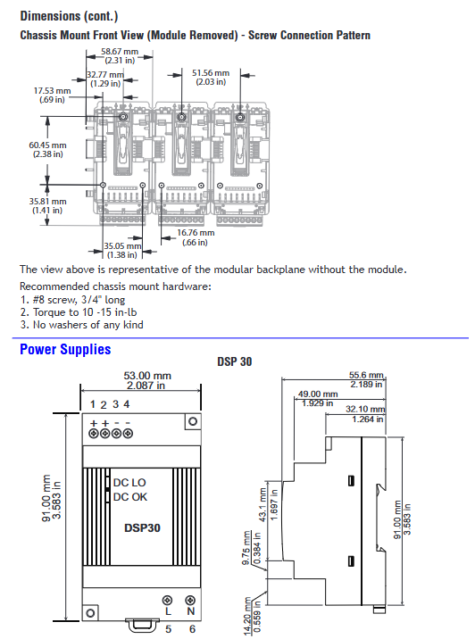
Guide rail preparation: Confirm that the guide rail meets the EN50022 standard (35 × 7.5mm), clean the surface of the guide rail, and ensure that there is no oil or rust.
Module fixation:
Insert the module from the hook above the guide rail, rotate the module to a vertical position, and hear a "click" sound to indicate that the buckle is locked.
When installing multiple modules, horizontally splice the modules to ensure complete contact of the backplane connectors, and check the flatness of the last module after installation.
- ABB
- General Electric
- EMERSON
- Honeywell
- HIMA
- ALSTOM
- Rolls-Royce
- MOTOROLA
- Rockwell
- Siemens
- Woodward
- YOKOGAWA
- FOXBORO
- KOLLMORGEN
- MOOG
- KB
- YAMAHA
- BENDER
- TEKTRONIX
- Westinghouse
- AMAT
- AB
- XYCOM
- Yaskawa
- B&R
- Schneider
- Kongsberg
- NI
- WATLOW
- ProSoft
- SEW
- ADVANCED
- Reliance
- TRICONEX
- METSO
- MAN
- Advantest
- STUDER
- KONGSBERG
- DANAHER MOTION
- Bently
- Galil
- EATON
- MOLEX
- DEIF
- B&W
- ZYGO
- Aerotech
- DANFOSS
- Beijer
- Moxa
- Rexroth
- Johnson
- WAGO
- TOSHIBA
- BMCM
- SMC
- HITACHI
- HIRSCHMANN
- Application field
- XP POWER
- CTI
- TRICON
- STOBER
- Thinklogical
- Horner Automation
- Meggitt
- Fanuc
- Baldor
- SHINKAWA
- Other Brands


