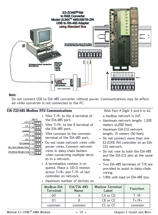
Watlow EZ-ZONE ® RMA (Access) module
3. Communication testing tools
Modbus RTU Test: Use Watlow Modbus RTU Diagnostic Tool (free), set baud rate=9600, address=1, read register 2500 (process value), verify communication is normal.
EtherNet/IP testing: Using Rockwell RSLogix software, add EtherNet/IP driver for RMA module, read implicit assembly (Input Assembly=1, Output Assembly=2), and verify data interaction.
Maintenance and troubleshooting
1. Daily maintenance
(1) Regular inspection (monthly)
Appearance inspection: Check if the module indicator lights (Power, Comm) are normal and there are no errors (red light constantly on=fault).
Wiring inspection: The terminals are not loose or oxidized, the shielding layer is well grounded, and there is no parallel wiring between the communication line and the power line.
SD card check: Check if the SD card is in place, with a remaining space of ≥ 10%, and regularly export logs (to avoid stopping recording when full).
(2) Annual maintenance
Power test: Use a multimeter to measure the power supply voltage (20.4-30.8V), with ripple ≤ 5%, to ensure stable power supply.
Communication test: Use diagnostic tools to verify that all protocol communication is normal, Modbus response time ≤ 100ms, Ethernet packet loss rate=0.
Battery check: Check if the RTC time is accurate, and replace the battery (BR1225) if the deviation is greater than 5 minutes.
2. Troubleshooting
(1) Common faults and solutions
Possible causes of malfunction, troubleshooting steps, and solutions
Module has no display, power supply is not connected, voltage is abnormal, module fault 1. Measure the voltage at terminal 98/99; 2. Check the fuse (if any); 3. Observe if the Power light is on. 1. Reconnect the wiring; 2. Replace the power supply; 3. Apply for RMA repair
Communication failure (Modbus) address/baud rate mismatch, wiring error, terminal resistance not connected 1. Check RMA and PLC parameters; 2. Check the CA/CB/CC wiring; 3. Measure bus voltage (2.5-5V) 1. Unified parameters; 2. Correct the wiring; 3. Connect a 120 Ω resistor at the beginning and end
Data recording does not start. SD card is not inserted/damaged, and log points are not configured. 1. Check if the SD card is recognized (Operations → Data Logging → Status); 2. Check the Log Point configuration. 1. Replace the SD card; 2. Reconfigure log points
Backup failed, memory/SD card full, module address conflict. 1. Check Available Memory; 2. Check if the Zone address is duplicated. 1. Clean up the storage; 2. Modify duplicate addresses
Ethernet unresponsive IP conflict, network cable failure, switch abnormality 1. Check if the IP is occupied; 2. Test the continuity of the network cable; 3. Check if the Link light is on. 1. Replace the IP address. 2. Replace the network cable; 3. Restart the switch
(2) Meaning of indicator lights
Meaning of indicator light status
Power (green) is constantly on, and the power supply is normal
Power (red) constantly on, abnormal power supply (overvoltage/undervoltage)
Comm (green) flashing communication active
Comm (red) constantly on communication fault (address/parameter error)
SD Card (green) flashing SD card read/write in progress
SD Card (red) constantly on SD card fault (unrecognized/damaged)
3. View fault logs
Enter Factory → Diagnostics Menu to view information such as Software ID, Serial Number, IP Actual Address, etc. Record Error Code (such as "E01=communication failure") when there is a fault for technical support to troubleshoot.

Typical application scenarios
1. Temperature control and monitoring of industrial ovens
System composition: 1 RMA (EtherNet/IP Gateway)+2 RMCs (Temperature Control)+1 RME (Digital I/O Expansion), with PC monitoring via Ethernet.
Function implementation:
RMC controls oven heating, RME collects door switch status, RMA records temperature data (1 record every 60 seconds, stored on SD card).
PC can view the temperature curve in real-time through EZ-ZONE Configurator, and trigger an email alarm (EtherNet/IP linkage) in case of abnormalities.
2. Backup of semiconductor process equipment configuration
System composition: 1 RMA (Enhanced Edition)+4 RMCs (Process Control) for semiconductor wafer heat treatment equipment.
Function implementation:
RMA regularly backs up the configuration of 4 RMCs (automatically backed up to SD card every morning), and automatically restores the configuration when replacing RMCs to reduce downtime.
Upload process parameters to MES system through Modbus TCP to achieve production data traceability.
3. Equipment monitoring in hazardous areas (Class 1 Div. 2)
System composition: 1 RMA (Class 1 Div. 2 certification)+1 RML (limit control), used for temperature monitoring of chemical reaction vessels.
Function implementation:
RML monitors the temperature of the reactor and triggers an RMA alarm output when it exceeds the limit, cutting off the heating power supply; RMA uploads data to the explosion-proof PLC via Modbus RTU.
Explosion proof junction boxes are used, and armored shielded wires are used for communication lines, meeting Class 1 Div. 2 safety requirements.
Ordering Information
Taking "RMAX-A3BD-AAA" as an example, the meaning of each segment of the model:
- ABB
- General Electric
- EMERSON
- Honeywell
- HIMA
- ALSTOM
- Rolls-Royce
- MOTOROLA
- Rockwell
- Siemens
- Woodward
- YOKOGAWA
- FOXBORO
- KOLLMORGEN
- MOOG
- KB
- YAMAHA
- BENDER
- TEKTRONIX
- Westinghouse
- AMAT
- AB
- XYCOM
- Yaskawa
- B&R
- Schneider
- Kongsberg
- NI
- WATLOW
- ProSoft
- SEW
- ADVANCED
- Reliance
- TRICONEX
- METSO
- MAN
- Advantest
- STUDER
- KONGSBERG
- DANAHER MOTION
- Bently
- Galil
- EATON
- MOLEX
- DEIF
- B&W
- ZYGO
- Aerotech
- DANFOSS
- Beijer
- Moxa
- Rexroth
- Johnson
- WAGO
- TOSHIBA
- BMCM
- SMC
- HITACHI
- HIRSCHMANN
- Application field
- XP POWER
- CTI
- TRICON
- STOBER
- Thinklogical
- Horner Automation
- Meggitt
- Fanuc
- Baldor
- SHINKAWA
- Other Brands


