
Allen Bradley 1746-NI8 Analog Input Module Application Case
Allen Bradley 1746-NI8 Analog Input Module
Product Core Positioning and Characteristics
(1) Basic positioning
1746-NI8 is an 8-channel analog input module of the SLC 500 series, used to collect DC voltage or current signals from industrial sites (such as sensor and transmitter outputs), convert analog signals into digital signals recognizable by PLC through built-in analog-to-digital (A/D) converters, achieve equipment status monitoring and process control, and adapt to fixed and modular SLC 500 processors.
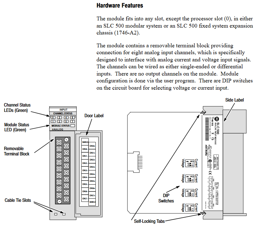
(2) Core functions and hardware features
Category specific description
Hardware design -8 high impedance input channels, supporting single ended or differential wiring;
-Comes with a detachable terminal block (spare part number 1746-RT25G) for easy wiring and maintenance;
-The panel contains 9 green LED indicator lights: 8 channel status lights (corresponding to 8 input channels), 1 module status light, which intuitively displays the operation and fault status;
-Side mounted DIP switch for selecting channel input type (voltage/current).
System compatibility - supports two interface modes, Class 1 and Class 3:
-Class 1 (default): Suitable for SLC 500 fixed type, SLC 5/01/02/03/04 processors, occupying 8 output configuration words and 8 input data words;
-Class 3 (Advanced): Only compatible with SLC 5/02/03/04 processors, with additional support for user-defined scaling and channel status word monitoring, occupying 12 output configuration words and 16 input words (including 8 data words and 8 status words).
Key feature - Automatic calibration: All enabled channels undergo continuous temperature compensation and automatic calibration without the need for manual triggering;
-Fault diagnosis: supports fault detection such as open circuit, over range, and configuration errors, and provides feedback through LED and status words;
-Filtering function: Programmable digital low-pass filtering (8 frequencies to choose from), balancing noise suppression and response speed.
Quick Start Guide
For users with experience using SLC 500, a simplified deployment process is provided, with the following core steps:
Equipment preparation: Screwdrivers, analog input devices (such as sensors), shielded cables (recommended Belden 8761), SLC processors and power supplies, and programming equipment (such as RSLogix 500) need to be prepared.
Hardware inspection: Confirm that the packaging contains 1746-NI8 modules and pre installed terminal blocks. If missing, please contact the supplier.
Power compatibility: The module is powered through the backplane and consumes 5V DC 200mA and 24V DC 100mA. It is necessary to ensure that the chassis power load is sufficient (refer to manual 1747-6.2 to calculate the total load).
DIP switch setting: Adjust the side DIP switch (OFF=voltage, ON=current) according to the input type (voltage/current).
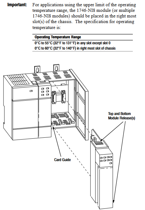
Module installation: Insert the chassis into any non processor slot while powered off (it is recommended to install it in the rightmost slot in high-temperature environments for higher temperature tolerance), and tighten the self-locking buckle.
Wiring: Use shielded cables to connect the sensor to the terminal block. Single ended signals can be short circuited to the common terminal, while differential signals should pay attention to the common mode voltage (≤± 10.5V). The shielding layer should be grounded at one end (channels 0-3 should be connected to the top shielding terminal, and channels 4-7 should be connected to the bottom).
System configuration: Set the module ID code (3526 for Class 1 and 12726 for Class 3) through programming software. Class 3 requires an additional configuration of 16 input words and 12 output words.
Channel configuration: Define channel configuration words (such as input type, data format, filtering frequency) in the ladder program, and download them to the module output image area through the COPY instruction.
Startup verification: It is normal for the module status light and the enabled channel light to remain on after power on; If the light flashes or does not light up, refer to Chapter 7 for troubleshooting.
Installation and wiring
(1) Installation specifications
Static protection: Wear a grounding wristband during operation to avoid touching the back panel pins, and store in an anti-static bag when idle.
Slot selection:
Modular chassis: can be installed in any slot except slot 0 (processor slot);
Fixed expansion chassis (1746-A2): Please refer to the compatibility table (if combined with OB16 module, confirm current load), and some combinations require external power supply.
Temperature adaptation: The working temperature of the regular slot is 0-55 ℃, and the rightmost slot is 0-60 ℃. Avoid approaching high heating modules (such as 32 point I/O modules) or strong interference sources (such as frequency converters).
Installation steps: Align the upper and lower guide slots of the chassis, slowly push them into the buckle lock, and install the 1746-N2 filling plate in the idle slot.
(2) Wiring requirements
Specification for Wiring Types
The terminal block has 18 detachable terminals, including 2 shielded terminals, supporting up to 14 AWG wires, and terminal screw torque ≤ 5 lb in (0.565 Nm).
The single ended input signal is connected positively to CHx (+) and negatively to CHx (-), and the multi-channel common terminal can be short circuited to reduce wiring.
The common mode voltage of the differential input signal source should be ≤± 10.5V. It is forbidden to connect the common terminal of the signal source to the module to avoid grounding loops.
The power module does not provide sensor power and needs to be separately matched with a DC power supply of the transmitter specifications (such as 24V DC).
Run basic configuration
(1) Module identification and addressing
ID code setting: The corresponding ID code (Class 1:3526, Class 3:12726) needs to be entered in the programming software. Early versions of RSLogix 500 only supported Class 1 and need to be upgraded to v1.30+to support Class 3.
Memory Mapping:
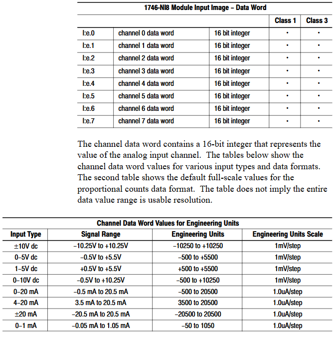
Class 1: Output image O: e.0-O: e.7 consists of 8 channel configuration words, while input image I: e.0-I: e.7 consists of 8 channel data words;
Class 3: The output image contains an additional O: e.8-O: e.11 (2 sets of scaling upper and lower limits), and the input image I: e.8-I: e.15 consists of 8 channel status words.
(2) Key parameter calculation
Module update time: The total sampling conversion time for all enabled channels is 0.75ms for a single channel and 6.0ms for 8-channel full configuration (independent of filtering frequency).
Channel response time:
Start time (enable until status word update): 101-107ms;
Shutdown time (from disabled to data reset): 1-7ms;
Reconfigure time (modify configuration): 101-107ms (excluding data format modifications).
Filtering and Anti aliasing:
The filtering frequency determines the step response (such as achieving 1% accuracy in 730ms for 1Hz filtering, and only 0.5ms without filtering);
Aliasing frequency=1/(number of enabled channels x 0.00075), channel 1 is 1333Hz, and channel 8 is 167Hz. It is necessary to ensure that the signal frequency is lower than the aliasing frequency.
Channel configuration and data processing
(1) Detailed Explanation of Configuration Words
Each channel configuration word (16 bits) defines the channel working mode, and the key bits have the following meanings:
Description of Range Function Options
The voltage (± 10V/1-5V/0-5V/0-10V) and current (0-20mA/4-20mA/± 20mA/0-1mA) of the 0-2 input type should be consistent with the DIP switch
3-5 data format engineering unit (1mV/1 μ A step) Scaled-for-PID(0-16383)、 Proportional counting (-32768-32767), NI4 compatible format, Class 3 user-defined
6-7 open circuit state is only valid for 4-20mA, with optional zero value, upper limit value, and lower limit value
8-10 filtering frequency 000=no filtering, 001=75Hz, 010=50Hz, 011=20Hz, 100=10Hz, 101=5Hz, 110=2Hz, 111=1Hz
11 channel enable 1=enabled (participating in sampling), 0=disabled (data reset)
12-15 reservation needs to be set to 0
(2) Data scaling
The digital output of the module needs to be converted into actual engineering units (such as temperature and pressure), supporting multiple scaling methods. Examples are as follows:
Engineering unit: directly corresponding to physical quantities (such as 4-20mA corresponding to 100-500 ℃, data word 5500 → 247.5 ℃);
Scaled for PID: adapted to SLC PID instructions, 0 corresponds to lower limit, 16383 corresponds to upper limit (e.g. 4-20mA corresponds to 212-932 ° F, data word 5500 → 453.71 ° F);
User defined (Class 3): Set two sets of zoom ranges through O: e.8-O: e.11 and map them proportionally (e.g. 0-10V corresponds to 0-200psi, data word 16600 → 166psi).
(3) Status word monitoring (Class 3)
The input images I: e.8-I: e.15 are channel status words, and the key bits provide feedback on the operating status
Position 0-2: Current input type;
Position 3-5: Current data format;
Bit 11: Channel enable status (1=enabled);
Bit 12: Open circuit error (1=detected);
Bit 13: Over range error (1=input exceeds upper limit);
Bit 14: Under range error (1=input exceeds lower limit);
Bit 15: Configuration error (1=invalid configuration word).

Example of trapezoidal logic
Provide ladder diagram examples of typical programming scenarios, including:
Initialization configuration: Use the first scan bit (S: 1/15) to copy the preset configuration word (stored in the N10 file) to the module output image area (such as O: 3.0-O:3.7) through the COP instruction, and batch enable 8 channels.
PID interface: Set the channel data to Scaled for PID format and directly use it as a process variable (PV) for PID instructions without intermediate scaling (e.g. I: 3.0 → PID control block N11:23).
Fault alarm: Monitor the open circuit error bit of the Class 3 status word (such as I: 3.8/12), trigger the output point (such as O: 2.0) to drive the alarm light.
Diagnosis and troubleshooting
(1) LED status interpretation
Solution to the cause of module status light channel status light malfunction
Always on, always on. Normal operation without operation required
Constant flashing, open circuit/over range/configuration error 1. Check wiring and sensors; 2. Confirm that the configuration word is valid; 3. Check the status word to locate the error type
Extinguish module fault/not powered on 1. Check the power supply of the backplane; 2. Re plug and unplug the module; 3. Contact technical support
Constant on/off channel not enabled. Set bit 11=1 in the configuration word to enable channel
(2) Common troubleshooting
Open circuit error: Only 4-20mA channel, check for sensor disconnection, loose terminals, response time ≤ 6ms (8-channel full configuration).
Over range error: Input signal exceeds the configured type range (such as 4-20mA channel input<3.5mA or>20.5mA), calibrate sensor or adjust configuration.
Configuration error: The configuration word position setting is invalid (such as setting the data format to 110), and the configuration word needs to be redefined.
Noise interference: If the analog signal fluctuates greatly, check the shielding grounding, stay away from the power line, or reduce the filtering frequency (if set to 1Hz).
(3) Spare parts and support
Replaceable spare parts: terminal block (1746-RT25G), terminal cover (1746-R13), manual (1746-6.8);
Technical support: Module fault symptoms, LED status, image data, processor model and firmware version are required. Contact Allen Bradley customer service (Americas: 1-888-565-4155; Europe:+800-44444-8001; Asia:+86-400-842-8599).
Application examples
Provide two practical cases covering both basic and advanced scenarios:
Basic case: Monitoring single-phase motor current, 4-20mA signal corresponding to 0-100A, channel 0 set as engineering unit+10Hz filtering, program converts data into BCD format to drive LED display screen (TOD command required).
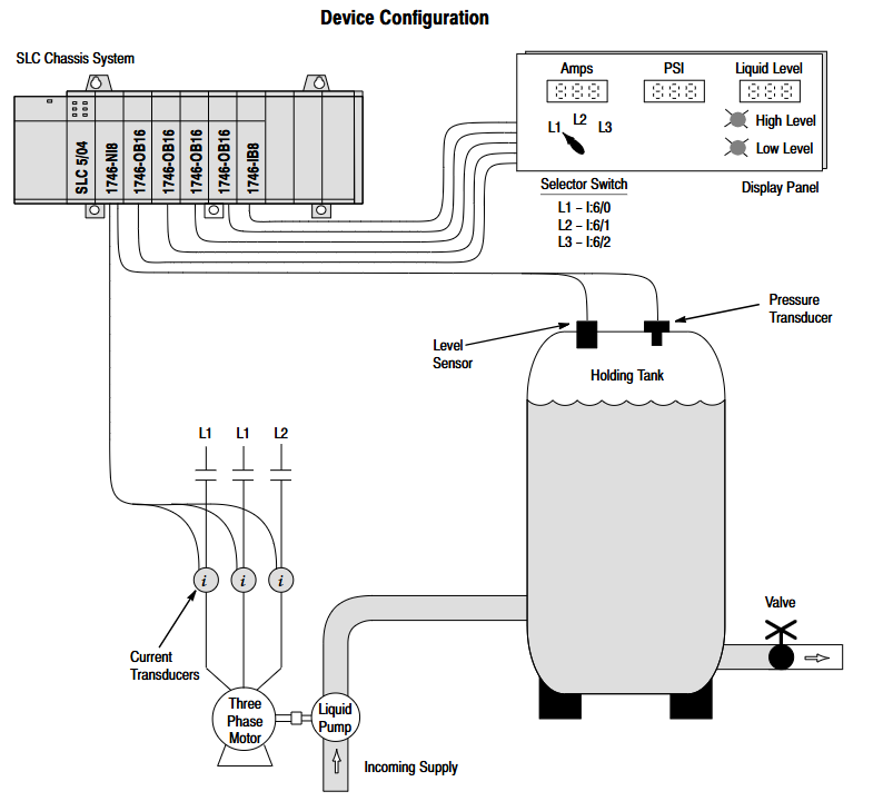
Advanced case: Multi parameter monitoring (three-phase motor current, tank pressure, liquid level), switching the display current phase sequence through a selection switch, triggering high and low level alarms when the liquid level exceeds the limit, and configuring different input types (current/voltage) for each of the 5 channels.
Technical Specifications
Electrical input channel: 8 channels (backplane isolation); Input impedance: 1M Ω; A/D conversion: successive approximation method; Common mode rejection ratio: DC ≥ 75dB, 50/60Hz ≥ 100dB; Accuracy: Voltage ± 0.1%, current ± 0.05% (0-60 ℃)
Physical dimensions: 127mm × 89mm × 152mm; weight: approximately 454g; protection level: IP20; Terminal: 18 positions detachable
Environmental working temperature: 0-55 ℃ (conventional slot), 0-60 ℃ (rightmost slot); Storage temperature: -40-85 ℃; Humidity: 5% -95% (without condensation); Hazardous Area Certification: Class I Division 2
- OMRON
- ABB
- General Electric
- EMERSON
- Honeywell
- HIMA
- ALSTOM
- Rolls-Royce
- MOTOROLA
- Rockwell
- Siemens
- Woodward
- YOKOGAWA
- FOXBORO
- KOLLMORGEN
- MOOG
- KB
- YAMAHA
- BENDER
- TEKTRONIX
- Westinghouse
- AMAT
- AB
- XYCOM
- Yaskawa
- B&R
- Schneider
- KONGSBERG
- NI
- WATLOW
- ProSoft
- SEW
- ADVANCED
- Reliance
- TRICONEX
- METSO
- MAN
- Advantest
- STUDER
- DANAHER MOTION
- Bently
- Galil
- EATON
- MOLEX
- DEIF
- B&W
- ZYGO
- Aerotech
- DANFOSS
- Beijer
- Moxa
- Rexroth
- Johnson
- WAGO
- TOSHIBA
- BMCM
- SMC
- HITACHI
- HIRSCHMANN
- Application field
- XP POWER
- CTI
- TRICON
- STOBER
- Thinklogical
- Horner Automation
- Meggitt
- Fanuc
- Baldor
- SHINKAWA
- Other Brands
- UniOP
- KUKA
- Iba
- Beckhoff
-
 OMRON B7AM-8B16 I/O Terminal Block
 -
 Fanuc A06B-6110-H026 Power Supply Module
 -
 Schneider TSXETG3021 Ethernet Gateway
 -
 OMRON CS1W-CLK21-V1 Controller Link Unit
 -
 NP1W6406T-Z704 PLC I/O Module
 -
 OMRON CJ1W-DA08C Analog Output Module
 -
 Yaskawa 3G3HV-A4022-CE AC Drive
 -
 OMRON NB7W-TW01B CP1L-EL20DR-D Power Panel
 -
 OMRON C500-NC103-E Position Control Unit
 -
 Steag Hamatech PLC DCS Servo Control System
 -
 Siemens 6SN1123-1AA00-0DA1 Power Supply Module
 -
 GE IC693CHS391H CPU & AD693CMM301A PLC Module
 -
 Siemens 6FC5303-0AF23-1AA1 PLC Control Panel
 -
 Square D CM4000T PowerLogic Circuit Monitor J1 F16
 -
 Siemens 6FX5002-5DG10-1BA0 MOTION-CONNECT 500 Cable
 -
 Schmersal SRB324ST 101195504 Safety Relay 24V
 -
 Mitsubishi 15050-PR02A PLC Circuit Board Module
 -
 OMRON CQM1-AD041 Analog Input PLC Module
 -
 Beckhoff EL5042 EtherCAT PLC Terminal Module
 -
 OMRON C200HW-MC402-E Motion Control Unit
 -
 C36TC0UA1100 Industrial Temperature Controller
 -
 NL8048BC24 12 Industrial Control LCD Module
 -
 OMRON R88D Servo Drive and Motor System
 -
 OMRON CS1W CLK21 V1 Controller Link Module
 -
 OMRON YASKAWA R7M A20030 S1 D Servo Motor
 -
 SIEMENS 6AV2128 3KB06 0AX1 Unified Comfort Panel
 -
 Schneider Electric METSEPM8240 PowerLogic Meter
 -
 Advanced AMCI 1PLC 1 31F Programmable Limit Switch
 -
 ABB PM582 ETH Programmable Logic Processor
 -
 SIEMENS 6FC5110 0CB01 0AA0 CPU Control Board
 -
 Schleicher P03GS13A CPU Module
 -
 Siemens 6SN1123-1AA00-0BA1 Power Module
 -
 Mitsubishi A1S61PN Power Supply Module
 -
 Yaskawa CPS-IONB DC Power Supply Module
 -
 Siemens 6ES7215-2BD00 CPU 215-2
 -
 Mitsubishi A2ACPU MELSEC PLC System Kit
 -
 ProSoft 3150-MCM Communication Module
 -
 Mitsubishi OSE104ET Incremental Encoder
 -
 OMRON CJ1W-AD081-V1 Analog Input Module
 -
 Broadcom BCM5464A1KRB Quad Port Ethernet IC
 -
 Modicon M221-24IO TM221C24 PLC 24 PNP Transistor
 -
 Allen-Bradley 1321-3R160-B Line Reactor 3R160B
 -
 Beckhoff CX1020-0012 Embedded PLC Module Specs
 -
 Turck BL20-PF-24VDC-D Power Feed Module Specs
 -
 Siemens 6SY7000-0AC37 Power Supply Module
 -
 Yaskawa SGDH-10DE-OY 1kW 400V Servo Drive Specs
 -
 Omron 3G3SV-BB015-E 1.5kW 220V VFD Specs
 -
 Uni-Pro CPU91-PLC J 23.020167X Processor Module
 -
 PASABAN MTC-3044 PLC Rack Power Supply 4835-A
 -
 XYCOM 3015T Operator Interface Panel BIN4.4.4
 -
 OMRON CJ1W-MD261 Mixed I/O Module
 -
 Omron NJ301-1100 PLC CPU eCat EIP Specs
 -
 Omron F500-C15-ETN Vision System PLC Module
 -
 Modicon M241-24IO TM/T2UK PLC with Ethernet
 -
 SIXNET YS-800-001 RTU PLC Module
 -
 BEMAC UST-202-D Interface Board 1307D V08B2
 -
 Yaskawa JANCD-MMOIC-02 Drive Circuit Board
 -
 ABB 3BSE005028R1 SDCS-COM-1 Comm Board
 -
 Omron 3G3MX2-A4110 A4150 Inverter Drives Specs
 -
 KEYENCE CA-E100 PLC Module
 -
 GE IC693ALG223-GB Analog Input Module Specs
 -
 ABB BAILEY IMMFP01 Multi Function Processor System
 -
 SIEMENS 6FC5372 0AA00 0AA1 NCU 7202 Controller
 -
Modicon TM241CE4 40I O Transistor Programmable Controller
-
 SIEMENS 6ES7 315 2EH13 0AB0 CPU 3152 PN DP
 -
 NORIS A1 91 PCB Card Rack Module System
 -
 SIEMENS 6ES7 313 5BE01 0AB0 Compact CPU
 -
 SCHNEIDER ELECTRIC S144B MICROLOGIC 60A Trip Unit
 -
 CNI PLC269 v3 Control Module Board Rev H
 -
ABB BAILEY IIMCP02 Processor Module
-
 OMRON NT20S ST121 EV3 Operator Interface Terminal
 -
 OMRON NS-CA001 Video Input Unit
 -
 GE Fanuc IC695CHS012 RX3i Backplane
 -
 Allen Bradley 2711E-K14C6 PanelView 1400e Terminal
 -
 Siemens Sinamics CCB 10000432.71 Power Cell
 -
 Siemens 6SL3210-1SE21-8UA0 Power Module PM340
 -
 Yaskawa CIMR-F7A20P4 AC Drive
 -
 Beckhoff EP1918-0002 EtherCAT Box I/O Module
 -
 OMRON CQM1-TC001 Temperature Control Module
 -
 GE Fanuc SGHA36AT0400 Industrial Contactor
 -
 OMRON NJ501-1500 PLC Machine Automation Controller
 -
 Mitsubishi MAZAK QX084 Power Supply MELDAS 500 CNC
 -
 B&R 0AC808.9 PLC Automation Module
 -
 OMRON CP1H-XA40DT1-D PLC Module
 -
 G&W Electric PLC15 5111 011 15kV Capnut Assembly
 -
 GE DS200SLCCG3AGH PCB Circuit Board
 -
 Siemens SINUMERIK 6FC3981-4FD PLC Extension
 -
 OMRON F300-DC I/O Image Processing Unit
 -
 FANUC A06B-0314-B002 AC Servo Motor
 -
 GC-S84 Programmable Controller Logic Module
 -
 PASABAN MONTELEC MTC3001-DC Drive Control PLC
 -
 Allen Bradley 100E460EJ11 Auxiliary Contactor
 -
 Bosch Rexroth 1070075337-101 Card Parameters
 -
 HMS Anybus AB7646-F Gateway Specifications
 -
 Bosch 062633-303401 CNC Servo PLC Card
 -
 TI 500-5023 Series PLC Power Supply
 -
 Siemens C98043-A7002-L1-12 Circuit Board
 -
 Omron E5CC-RX3A5M-000 Controller
 -
 CN-8032-L Profinet Network Adapter Module
 -
 Siemens 3TK2804-0BB4 Safety Relay Details
 -
 Toledo TTLM-2-1M I/O Load Module
 -
 NORIS A1-91 PLC Rack Board Specifications
 -
 Mitsubishi A3ACPUR21 MELSEC PLC CPU Module
 -
 Beckhoff EP7041‑3002 EtherCAT Box Digital Input Module
 -
 REER EOS2E 1053 EOS2R 1053 Safety Light Curtain
 -
 Mitsubishi Q80BD-J71BR11 MELSECNET/H Interface Board
 -
 Omron 3G3IV-B4220-EV2 VFD 400V 22kW
 -
 Allen-Bradley 96844671 1785-LT3 PLC-5/12 Processor Module
 -
 Pasaban MTC3001-DC Drive Control PLC Module
 -
 Omron CJ1M-CPU11 V4.0 PLC CPU Module
 -
 ABB CM579-PNIO B3 Communication Module
 -
 B&R X20 AI 4221 Analog Module
 -
 Siemens 6SY7000-0AC80 PLC Module
 -
 GE 531X300CCHAFM5 Control Card
 -
 AB 810-A15C Inverse Time Relay
 -
 WITTENSTEIN LP120X-MF2-20 Planetary Gear
 -
 Mitsubishi Kakoki E-01B-4130 PLC I/O Modules
 -
 ABB DSQC643 Safety Control Board
 -
 Siemens G26004-A2105-P100-2 PCB
 -
 OMRON F350-C10E Image Processing Unit
 -
 FUJI UG430H-TS1 HMI Touch Panel
 -
 Westronics CB100188-01 Rev F Board
 -
 Siemens 7MH4900-3AA01 Weighing Module
 -
 Gilbert & Nash Tracker 2000 Control Cabinet
 -
 OMRON CJ1M-CPU22 CPU Unit
 -
 OMRON F3SJ-E0625P25 Light Curtain
 -
 Siemens 3VA2340-5HL32-0AA0 Breaker
 -
 Mitsubishi Melsec A61P A2NCPU PLC System


