
Bently 3500/50M tachometer module
Bently 3500/50M tachometer module
Product Overview
Core functions
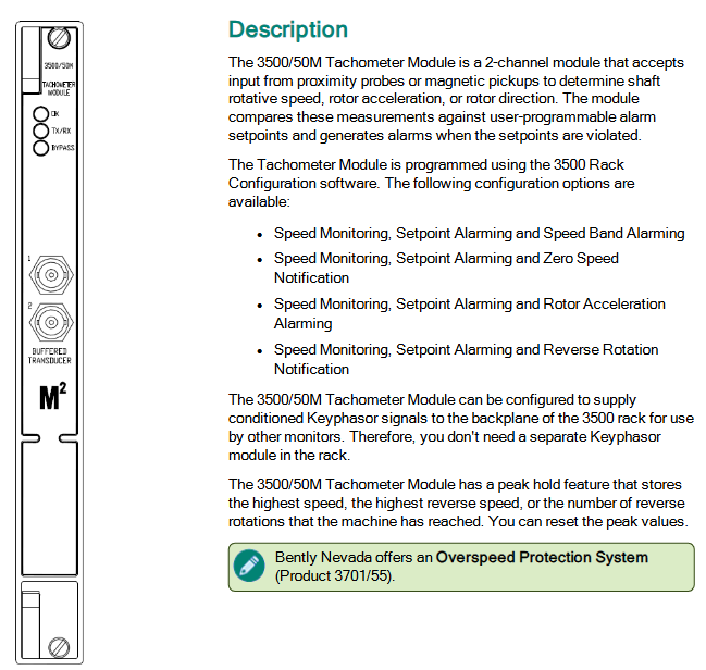
The 3500/50M tachometer module is a dual channel module that can receive input signals from proximity probes or magnetic pickups, used to measure shaft speed, rotor acceleration, or rotor steering, and compare these measured values with user programmable alarm settings. When the set values are exceeded, an alarm is generated.
Main features
Multiple configuration options: supports multiple configurations such as speed monitoring, set value alarm, speed band alarm, zero speed notification, rotor acceleration alarm, reverse rotation notification, etc.
Signal supply: It can be configured to provide conditioned Keyphasor signals to the rear 3500 rack backplane without the need for separate Keyphasor modules in the rack.
Peak hold function: Stores the maximum speed, maximum reverse speed, or number of reverse rotations reached by the machine, and the peak value can be reset.
Technical specifications
1. Input parameters
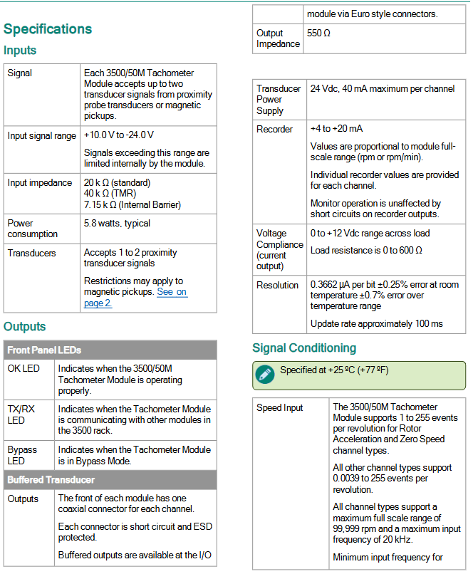
Signal input: Each module can receive up to 2 sensor signals from proximity probes or magnetic pickups, with an input signal range of+10.0 V to -24.0 V. Signals outside the range will be restricted internally by the module.
Input impedance: The standard is 20 k Ω, TMR is 40 k Ω, and the internal barrier is 7.15 k Ω.
Sensor power supply: 24 Vdc, maximum 40 mA per channel.
Power consumption: Typical value of 5.8 watts.
Speed input: supports 1 to 255 events per revolution; The minimum input frequency of the proximity sensor is 0.0167 Hz (1 rpm at 1 event/rev); The minimum input frequency for passive magnetic pickups is 3.3 Hz.
2. Output parameters
Analog output: proportional to the module's full-scale range (rpm or rpm/min), each channel provides independent recorder values, and monitoring operations are not affected by recorder output short circuits; The voltage dependence of the current output is 0 to+12 Vdc (load resistance 0 to 600 Ω).
Resolution: 0.3662 µ A/bit, with an error of ± 0.25% at room temperature and ± 0.7% over the entire temperature range. The update rate is approximately 100 ms.
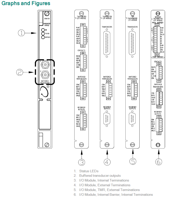
Front panel LED:
OK LED: Indicates that the module is operating normally.
TX/RX LED: Indicates that the module is communicating with other modules in the 3500 rack.
Bypass LED: Indicates that the module is in bypass mode.
3. Signal conditioning and accuracy
Threshold: The automatic threshold is applicable to any input above 0.0167 Hz (1 event/rev at 1 rpm), triggering a minimum signal amplitude of 1 V peak to peak; The manual threshold can be selected within the range of+9.5 Vdc to -23.5 Vdc, with a minimum trigger signal amplitude of 500 mV peak to peak.
Lag: Users can choose within the range of 0.2 to 2.5 volts.
Accuracy:
Speed accuracy: ± 0.1 rpm when<100 rpm; ± 1 rpm between 100 and 10000 rpm; ± 0.01% true shaft speed between 10000 and 99999 rpm.
Speed/minute accuracy: ± 20 rpm/min.
4. Alarm parameters
Alarm setting value: Each channel can set alarm level 1 (set value) for the measured value, which can be adjusted within the range of 0 to 100% of the full range of each measured value through software configuration.
Alarm delay: Alarm 1 has a delay of 1 to 60 seconds (1-second interval); Alarm 2 has a delay of 1 to 60 seconds (0.1 second interval).
Physical and installation parameters
Physical parameters
1. Monitoring module (motherboard)
Dimensions (height x width x depth): 241.3 mm x 24.4 mm x 241.8 mm (9.50 in x 0.96 in x 9.52 in)
Weight: 0.82 kg (1.8 lb)
2. I/O module
Barrier free I/O module
Weight: 0.20 kg (0.44 lb)
I/O module with internal barrier
Dimensions (height x width x depth): 241.3 mm x 24.4 mm x 163.1 mm (9.50 in x 0.96 in x 6.42 in)
Weight: 0.46 kg (1.01 lb)
Installation parameters
1. Rack space requirements
Monitoring module: occupying 1 full height front-end slot
I/O module: occupies 1 full height backend slot
2. Wiring and accessories
External terminal block (ET block)
To be used in conjunction with I/O modules with external terminals, terminal blocks and cables need to be ordered separately.
Supports European connectors and terminal block connectors, with specific models including 125808-05 (tachometer ET block, European connector), 128015-05 (tachometer ET block, terminal block connector), etc.
cable
Tachometer signal to ET block cable (135101-AAAA-BB): Available in lengths of 5 feet (1.5 meters), 7 feet (2.1 meters), 10 feet (3.0 meters), etc., supporting assembled or unassembled states.
Recorder output to ET block cable (129529-AAAA-BB): The length specification is the same as the above cable, and it also supports assembly or non assembly.
Installation restrictions
External terminal blocks cannot be used in conjunction with I/O modules with internal terminals.
I/O modules with TMR (Triple Modular Redundancy) require the use of bus type external terminal blocks.
Environment and Compliance
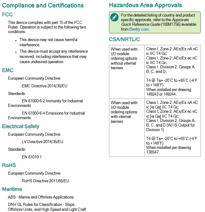
Hazardous Area Certification: Supports CSA/NRTL/C, ATEX/IECEx and other certifications, suitable for Class I, Zone 2 or Division 2 hazardous environments (depending on whether the I/O module is equipped with internal barriers).
Electromagnetic compatibility (EMC): Complies with EN 61000-6-2 (industrial environment immunity) and EN 61000-6-4 (industrial environment emission) standards.
Electrical safety: comply with LV Directive 2014/35/EU and EN 61010-1 standards.
- OMRON
- ABB
- General Electric
- EMERSON
- Honeywell
- HIMA
- ALSTOM
- Rolls-Royce
- MOTOROLA
- Rockwell
- Siemens
- Woodward
- YOKOGAWA
- FOXBORO
- KOLLMORGEN
- MOOG
- KB
- YAMAHA
- BENDER
- TEKTRONIX
- Westinghouse
- AMAT
- AB
- XYCOM
- Yaskawa
- B&R
- Schneider
- KONGSBERG
- NI
- WATLOW
- ProSoft
- SEW
- ADVANCED
- Reliance
- TRICONEX
- METSO
- MAN
- Advantest
- STUDER
- DANAHER MOTION
- Bently
- Galil
- EATON
- MOLEX
- DEIF
- B&W
- ZYGO
- Aerotech
- DANFOSS
- Beijer
- Moxa
- Rexroth
- Johnson
- WAGO
- TOSHIBA
- BMCM
- SMC
- HITACHI
- HIRSCHMANN
- Application field
- XP POWER
- CTI
- TRICON
- STOBER
- Thinklogical
- Horner Automation
- Meggitt
- Fanuc
- Baldor
- SHINKAWA
- Other Brands
- UniOP
- KUKA
- Iba
- Beckhoff
-
 Basler SSR 125-12NF Static Regulator 9 1859 00 106
 -
 Basler BE1-BPR Breaker Protection Relay 9272000315
 -
 Basler SSR 63-12 Static Regulator 9 1859 00 101
 -
 Basler AEM-2020 Analog Expansion Module
 -
 Basler BE 25231-001 Transformer BE25231001
 -
 Basler MVC 108 Manual Voltage Control 9037000102
 -
 Basler PSS-100-Y5 Power System Stabilizer 0.1-5.0Hz
 -
 Basler Electric BE1A-25-M1G-A6T-N4V1F Sync-Check Relay
 -
 Basler Electric SR8A2B10B1A Static Voltage Regulator
 -
Basler Electric SR8A2B10B1A Static Voltage Regulator
-
Basler Electric SSR 125-12 Static Voltage Regulator 9185900102
-
 Basler Electric 90-73900-102 Power Supply (Westinghouse 2374A07G03)
 -
 Basler Electric 9400200117 Control Power Unit 12/24VDC 20W
 -
Basler Electric BE1-87G Solid State Generator Differential Relay
-
 Basler Electric BE1-32R Style C3ED1TA0S1F Solid State Protective Relay
 -
Basler Electric SR32A2B05B3E Static Voltage Regulator
-
 Basler Electric SR8A2B06B3A Static Voltage Regulator
 -
Basler MOC3502 90-72300-116 Motor Potentiometer
-
 Basler SR4A2310B1A Static Voltage Regulator
 -
 Basler Electric 90-88800-102 PRS-250 Veri-Sync Relay
 -
Basler Electric 90-88800-102 PRS-250 Veri-Sync Relay
-
Basler SR4A-2B05A3E Static Regulator SR4A2B05A3E
-
 Basler 9-0723-00-130 9072300130 Control Module
 -
 Basler BE1-79MA10A6JC0L0F Reclosing Relay
 -
 Basler CBS-377 Current Boost System 91096001
 -
Basler SR4A1B05A3A Static Regulator 480V 62.5V 10VA
-
 Basler BE159N A7ED1JC0S0F Protective Relay BE159N-0
 -
 Basler BE3-25A Auto-Synchronizer S.No. 728
 -
 Basler BE1-50 Instantaneous Overcurrent Relay G4EA1RG0N0F
 -
 Basler Electric KT3B Voltage Regulator
 -
 Basler Electric ACA2500-14GCSYM GigE Camera
 -
 Basler Electric XR2002F Voltage Regulator
 -
 Basler Electric BE1-50 Instantaneous Overcurrent Relay F2EA1PA0N5F
 -
 Basler Electric CBS 212A Current Boost System
 -
Basler Electric BE147NE3FE1PC3N3F Negative Sequence Voltage Relay
-
 Basler Electric BE1-79MA10A6JC0L0F Automatic Reclosing Relay
 -
Basler Electric BE1-59N A6E E1C B0N1F Neutral Overvoltage Relay
-
 Basler Electric MVC 108 Manual Voltage Control
 -
 Basler Electric BE1-59-A4E-E1C-A0N0F Overvoltage Relay
 -
Basler BE1-57/27R Solid State Protective Relay
-
 Basler BE3-25AX Time Overcurrent Relay
 -
BASLER ELECTRIC BE1-24/A1EF1JC1N0F / BE124A1EF1JC1N0F Overvoltage Relay
-
Basler Electric Solid State Protective Relay BE1-32R Style B2ED1PB0N0F
-
Basler BE3-51-3E1E1 9320000110 24VDC Overcurrent Relay
-
 Basler UFOV 260A Underfrequency Overvoltage Module
 -
 Basler 50F4EA1PA0N0F Instantaneous Overcurrent Relay
 -
Basler BE1-50 Instantaneous Overcurrent Relay
-
 Basler BE1-32 Solid State Protective Relay
 -
Basler SCP 250-G-60 VAR Power Factor Controller
-
Basler BE1-59N A5EE1KC0N0F Ground Fault Relay
-
Basler BE1-79A Reclosing Relay
-
Basler BE1-32R E1EA1OA0N0F Reverse Power Relay
-
 Basler DCQA-103 DCQC104-1 CMX-7D Circuit Board
 -
 Basler SSR125-12 Static Regulator 918500102
 -
Basler 90 17709 112 Regulator Control Board
-
 Basler AVC63-4 AVC634 Voltage Regulator
 -
 Basler 9 1049 04 100 PC Board Control Module
 -
Basler SR4A-2B03B3A Static Voltage Regulator
-
 Basler SR8A-2B15B3A Static Voltage Regulator
 -
 Basler KR7FFX Static Regulator 840V
 -
 Basler EL200-7 Voltage Regulator 90-660VAC 7A
 -
 Basler PRP210-1 Reverse Power Relay 9056300102
 -
 Basler SSR 63-12 Static Regulator 600VAC
 -
 Basler 9289901106 Digital Board
 -
Basler DECS100 Voltage Regulator DECS100A01
-
Basler Electric CEM-2020 Contact Expansion Module
-
Basler Electric BE3-25-1 C1 N4 Synchronizing Check Relay
-
Basler Electric ACA2000-50GM GigE Camera 2MP 50fps
-
 Basler Electric ACA2240-20GMSYM GigE Camera Sony IMX264
 -
Basler BE1-50G Ground Overcurrent Relay
-
Basler PRS250 Veri-Sync Relay
-
Basler MOC2199 Output Module
-
 Basler UFOV 260A Underfrequency Overvoltage Module
 -
 Basler BE-15482-001 Control Module
 -
Basler LSP4-7 Protective Relay
-
 Basler SCP 250-G-60 VAR Power Factor Controller
 -
Basler BE146N Negative Sequence Overcurrent Relay
-
Basler APR63-5 Automatic Voltage Regulator
-
Basler 9507900107 SR8A Retrofit Voltage Regulator
-
Basler BE1-320 Directional Power Relay
-
 Basler KR7F Voltage Regulator 9116200100
 -
Basler UFOV 260A Overvoltage Protective Module
-
 Basler AEC63-7 Analog Excitation Controller
 -
Basler 9992D90G01 Control Module
-
Basler 6966D22G01 Control Board
-
Basler 6965D40G01 Control Board
-
 Basler BE1-50/51M-104 Overcurrent Relay
 -
Basler BE1-BPR Programmable Breaker Relay
-
 BASLER Electric SSR 125-9 1256 00 102 Static Voltage Regulator
 -
Basler Electric MVC 112 Manual Voltage Control
-
 Basler Electric 9321000102 Control Module
 -
 Basler Electric RA-70-MDCT7 Rectifier Assembly
 -
 Basler Electric ACA1300-60GM GigE Camera
 -
 Basler Electric 6427C85G01 Interface Board
 -
Basler Electric 6965D05G01 Control Board
-
Basler Electric ACA2500-14UC Current Transducer
-
Basler Electric 9170206111 Protective Relay
-
Basler Electric BE1-11-G6D1M1J1P0E000 Protection Relay
-
Basler Electric BE1-50/51B-107 Overcurrent Relay
-
 Basler 9121000106 Voltage Controller
 -
 Basler B3E-E1P-A0N0F Solid State Protective Relay
 -
 Basler 9121000106 Manual Voltage Control
 -
Basler PRP320 Motor Pull-out Relay
-
 Basler SSE-N 250-9KW Shunt Exciter Regulator
 -
 Basler BE1-50-51B-107 Overcurrent Relay
 -
 BASLER ELECTRIC MVC 108 MANUAL VOLTAGE CONTROL MODULE 9 0370 00 102
 -
Basler BE1-59N-A7E-D1J-D0N0F Ground Overvoltage Relay
-
Basler BE1-46N-G1E-B8P-B0N0F Negative Sequence Overcurrent Relay
-
Basler BE1-951 Overcurrent Protection System
-
 Basler Electric MOC2199 Motor Operated Potentiometer
 -
 Basler Electric BE1-60 Voltage Balance Solid State Relay B1FA1C1M1F
 -
Basler Electric BE1-67N Directional Overcurrent Relay
-
Basler Electric PIA2400-17GM Interface Module
-
 Basler Electric V6RAB Rectifier Module
 -
Basler Electric BE1-32R Reverse Power Relay B2E E1R A0N1F
-
Basler Electric IFM-150 Firing Circuit Chassis 120V AC
-
 Basler Electric IFM-102 Firing Circuit Chassis 120V AC
 -
 Basler Electric 9170206111 NSNP Control Module
 -
Basler Electric SSR 63-12 Static Voltage Regulator
-
 Basler UFOV 260A Overvoltage Protective Module
 -
Basler SCA1300-32GM CCD Camera Lens Enclosure
-
Basler BA1-27 Under Voltage Relay
-
Basler 149D866G06 Control Board
-
 Basler 9072300130 Power Supply Module
 -
Basler CBS 305 Current Boost System
-
 Basler BE1-60 Voltage Balance Relay
 -
 Basler Electric CBS 212 Current Boost System Sensing 120/240VAC 50/60Hz 10VA
 -
 Basler MVC-300 Manual Voltage Control Unit


