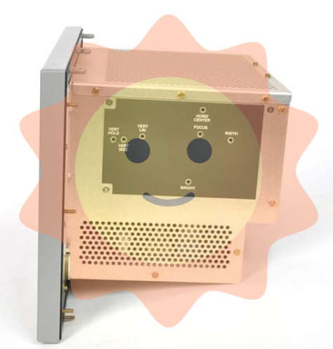
Tektronix 370B Programmable Curve Tracer
Key advantages: digital storage (flicker free display), precise cursor measurement (minimum resolution of 100pA), GPIB remote control, pulse mode (reducing device power consumption).
Measurement method: Use the WINDOW cursor to select adjacent curves, and the CRT will automatically display hFE (such as 250).
2. Field effect transistor (N-channel enhanced type)
Measurement parameters: ID-VDS curve gm、IDSS;
Key settings:
Configuration: CONFIG → BASE STEP GEN;
Collector power supply: MAX PEAK VOLTS=40V, POLYITY=+DC;
Step generator: VOLTAGE mode, 500mV/step, 8 steps;
Measurement method: Fit the ID-VGS curve with the f LINE cursor, and the slope is gm (e.g. 40mS).
3. Zener diode
Measurement parameters: reverse breakdown voltage (Vz), leakage current (IR);
Key settings:
Collector power supply: MAX PEAK VOLTS=400V, POLYITY=- DC;
Vertical sensitivity: 10 μ A/div (for IR measurement), 1mA/div (for breakdown current measurement);
Measurement method: The DOT cursor is positioned at the breakdown inflection point, and the CRT displays Vz (such as 12V).
GPIB remote control
1. Command format and examples
Basic format: keywords (abbreviations must include uppercase parts)+parameters, multiple commands separated by semicolons;
Example 1: Set collector power polarity: CSPOL PDC (PDC=+DC);
Example 2: Read the status of the stepper generator: STPgen? Return STPGEN NUMBER: 5, PULSE: OFF, OFFSET: 0.00, INVERT: OFF, MULT: OFF, CURRENT: 1.0E-3.
2. Data transmission process (waveform data)
Sending preamble query: WFMpre? Return waveform parameters (such as sampling point 1024, X-axis unit V);
Sending curve data query: CURVE? Return binary data (2-byte count+4096 byte coordinates+1-byte checksum);
Receiving data: The controller parses the data and converts it into a V-I curve (X=voltage, Y=current).
3. Common status codes
Suggestions for handling the meaning of status bytes (decimal)
65 power on completed normally, measurement can begin
97 command errors (such as syntax errors) check the command format, refer to Table 4-6
98 Execution error (such as parameter out of range) Confirm that the parameter is within the allowable range (such as AUX voltage ± 40V)
192 Device Specific Events (such as Full Floppy Disk) Replace Floppy Disk or Delete Old Data
Maintenance and troubleshooting
1. Self inspection process
Power on self-test: automatically detects ROM/RAM/buttons after powering on, displays SELETEST PASS as normal, flashes 0/1 indicates ROM error;
Detailed self-test: Press and hold FAST/SHIFT during startup, sequentially check the LED, display quality, and buttons, and press FAST/SHIFT to exit.
2. Common faults and solutions
Possible causes and solutions for the fault phenomenon
Collector power supply disabled (COL. Disabled) protection cover not closed, over temperature closed protection cover/waiting for cooling (COL. RECORDED prompt for recovery)
FD Read Error: The floppy disk is damaged and not formatted. Replace the floppy disk or perform formatting (FAST/SHIFT+SAVE → SAVE)
Insufficient cursor display intensity, mode error adjustment READOUT/CURSOR intensity, confirm in STORE/VIEW mode
3. Cleaning and maintenance
External cleaning: Use neutral cleaner and dust-free cloth to wipe the panel, and use ethanol to wipe the CRT;
Internal cleaning: Only qualified personnel are allowed to operate, use low-pressure compressed air (9psi) to blow off dust, and prohibit the use of high-pressure air (to prevent ESD);
Calibration cycle: It is recommended to calibrate once a year, referring to the performance verification process in Appendix A.
- ABB
- General Electric
- EMERSON
- Honeywell
- HIMA
- ALSTOM
- Rolls-Royce
- MOTOROLA
- Rockwell
- Siemens
- Woodward
- YOKOGAWA
- FOXBORO
- KOLLMORGEN
- MOOG
- KB
- YAMAHA
- BENDER
- TEKTRONIX
- Westinghouse
- AMAT
- AB
- XYCOM
- Yaskawa
- B&R
- Schneider
- Kongsberg
- NI
- WATLOW
- ProSoft
- SEW
- ADVANCED
- Reliance
- TRICONEX
- METSO
- MAN
- Advantest
- STUDER
- KONGSBERG
- DANAHER MOTION
- Bently
- Galil
- EATON
- MOLEX
- Triconex
- DEIF
- B&W
- ZYGO
- Aerotech
- DANFOSS
- Beijer
- Moxa
- Rexroth
- Johnson
- WAGO
- TOSHIBA
- BMCM
- SMC
- HITACHI
- HIRSCHMANN
- Application field
- XP POWER
- CTI
- TRICON
- STOBER
- Thinklogical
- Horner Automation
- Meggitt
- Fanuc
- Baldor


