
Tektronix 370B Programmable Curve Tracer
Key advantages: digital storage (flicker free display), precise cursor measurement (minimum resolution of 100pA), GPIB remote control, pulse mode (reducing device power consumption).
Tektronix 370B Programmable Curve Tracer
Basic Information and Quality Assurance Policy
Product positioning and applicable scenarios
Core function: Measure the static/dynamic characteristics of semiconductor devices and support the drawing of voltage current (V-I) characteristic curves for bipolar transistors, field-effect transistors (FETs), diodes, thyristors (SCR), and other devices.
Key advantages: digital storage (flicker free display), precise cursor measurement (minimum resolution of 100pA), GPIB remote control, pulse mode (reducing device power consumption).
Safety regulations and system installation
1. Core security requirements
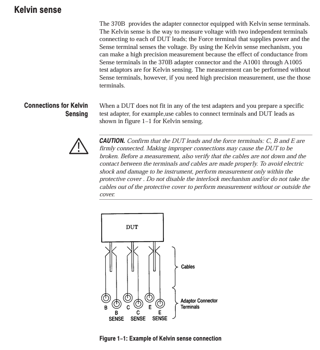
Interlocking system: The test adapter must be equipped with a protective cover. When there is no cover, the collector power supply will be automatically disabled, and the red Warning light will turn off (the light will turn on when there is a cover, indicating dangerous voltage).
Live operation taboos: Do not plug or unplug when connecting the probe/test line to the voltage source, and do not remove the protective cover for measurement.
Power safety: Before replacing the power supply, it is necessary to cut off the power and confirm that the LINE VOLTAGE SELECTOR (115V/230V) matches the local power supply. The fuse specifications cannot be mixed (4A for 115V and 2A for 230V).
2. System installation process
(1) Power configuration
Confirm the LINE VOLTAGE SELECTOR on the Rear panel: select 115V/230V for NOMINAL and HIGH-LOW for RANGE (e.g. 115V HIGH corresponds to 107-132V).
Check fuses: Open the Rear panel fuse holder. For 115V models, use a 125V/4A fast melting fuse (159-0259-00), and for 230V models, use a 250V/2A fast melting fuse (159-0260-00).
Connect the power cord: Select the corresponding plug according to the region (such as standard plug for North America or A1 option plug for Europe).
(2) GPIB settings
Rear panel GPIB Terminator and Address switch: Set the address (0-31, 31 is offline) and select the termination symbol (EOI/LF).
Cable connection: Use standard GPIB cables (such as 012-0991-00, 2m) to connect the controller to 370B, with a maximum of 15 devices in the system.
Address verification: Press and hold the FAST/SHIFT+LOCAL keys, and the CRT will display the GPIB address and termination symbol.
(3) Test adapter installation
Standard adapters: A1001 (blank), A1002 (serial), A1005 (axial lead), align with A1006-A1010 interface during installation, and do not forcefully install double width adapters to the right interface.
Core Function Operation Guide
1. Key controls on the front-end panel
(1) Collector Supply Control
Key parameters of control item function description
MAX PEAK VOLTS selects peak voltage range 16V/80V/400V/2000V (4th gear)
MAX PEAK POWER selects maximum peak power of 0.08W/0.4W/2W/10W/50W/220W (6th gear)
Polarity selects 7 output polarities and modes:+LEAKAGE (measuring emitter current, sensitivity x 1000),+DC, AC, etc
VARIABLE regulates the output ratio from 0.0% to 100.0% (with a step size of 0.1%)
LOOPING COMPENSATION Compensation parasitic capacitance maximum compensation 100pF
(2) Step Generator Control
Key parameters of control item function description
OUTPUT MODE Select output type: current (50nA-200mA/step), voltage (50mV-2V/step)
NUMBER OF STEPS: Select the number of steps from 0 to 10 (only output offset when 0 steps)
PULSE selects the pulse modes SHORT (80 μ s), LONG (300 μ s), OFF
OFFSET adjustment offset ± 10 x step amplitude (step size 1%)
Inverted output polarity is only valid in EMITTER COMMON mode
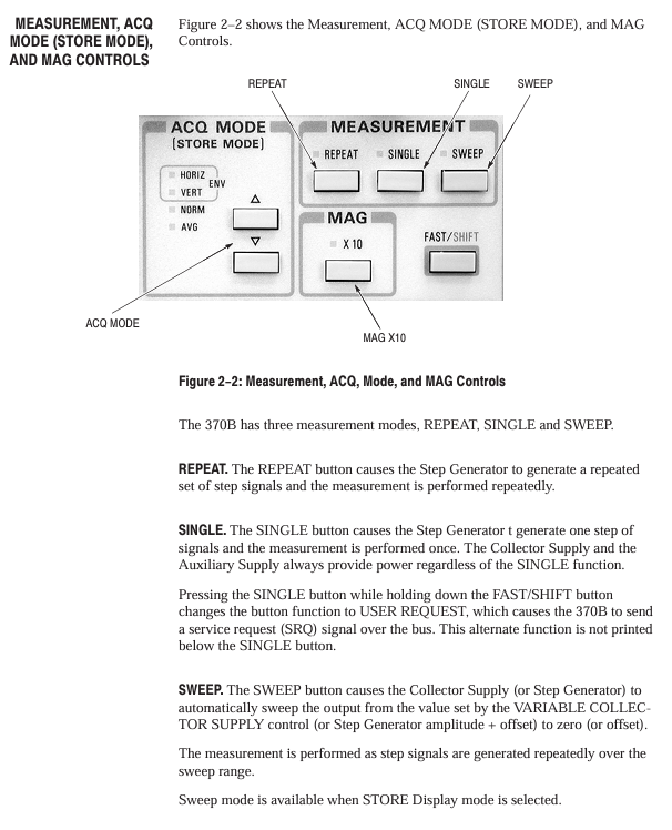
(3) Digital Storage and Display Control
Storage mode:
NON STORE: Real time simulation display (no storage);
STORE: Digital storage (1024 points/axis, resolution 10 bits);
VIEW: Call the storage curve (16 IC memories/64 floppy disks).
Collection mode:
AVG: 16 times average (noise reduction);
ENV: Vertical/Horizontal Envelope (Thermal Drift);
Norm: Conventional collection.
Cursor measurement:
DOT: Single point measurement (reading voltage/current);
F LINE: Functional line measurement (on resistance, intercept voltage);
WINDOW: Window measurement (hFE, gm).
2. Basic measurement process (taking diode forward characteristics as an example)
Install adapter: Insert the A1005 axial lead adapter into the right interface, insert the diode (anode connected to collector, cathode connected to emitter), and close the protective cover.
Configure collector power supply:
Choose 16V for MAX PEAK VOLTS, 0.4W for MAX PEAK POWER, and+DC for POLYTY.
Configure stepper generator:
Select CURRENT for OUTPUT MODE, 1mA/step for STEP AMPLITUDE, and 5 for NUMBER OF STEPS.
Start measurement:
Press MEASURE → REPEAT, adjust the VARIABLE collector power supply to 100%, and the CRT displays a positive V-I curve.
Cursor measurement:
Press CURSOR → DOT, move the cursor to the conductive area, and the CRT displays the forward voltage (such as 0.7V) and current (such as 5mA).
Typical measurement applications
1. Bipolar transistor (NPN type)
Measurement parameters: IC-VCE curve hFE、VCE (sat)、ICE0;
Key settings:
Configuration: CONFIG → BASE STEP GEN (emitter common ground);
Collector power supply: MAX PEAK VOLTS=80V, POLYITY=+DC;
Stepper generator: CURRENT mode, 50 μ A/step, 10 steps;
Measurement method: Use the WINDOW cursor to select adjacent curves, and the CRT will automatically display hFE (such as 250).
2. Field effect transistor (N-channel enhanced type)
Measurement parameters: ID-VDS curve gm、IDSS;
Key settings:
Configuration: CONFIG → BASE STEP GEN;
Collector power supply: MAX PEAK VOLTS=40V, POLYITY=+DC;
Step generator: VOLTAGE mode, 500mV/step, 8 steps;
Measurement method: Fit the ID-VGS curve with the f LINE cursor, and the slope is gm (e.g. 40mS).
3. Zener diode
Measurement parameters: reverse breakdown voltage (Vz), leakage current (IR);
Key settings:
Collector power supply: MAX PEAK VOLTS=400V, POLYITY=- DC;
Vertical sensitivity: 10 μ A/div (for IR measurement), 1mA/div (for breakdown current measurement);
Measurement method: The DOT cursor is positioned at the breakdown inflection point, and the CRT displays Vz (such as 12V).
GPIB remote control
1. Command format and examples
Basic format: keywords (abbreviations must include uppercase parts)+parameters, multiple commands separated by semicolons;
Example 1: Set collector power polarity: CSPOL PDC (PDC=+DC);
Example 2: Read the status of the stepper generator: STPgen? Return STPGEN NUMBER: 5, PULSE: OFF, OFFSET: 0.00, INVERT: OFF, MULT: OFF, CURRENT: 1.0E-3.
2. Data transmission process (waveform data)
Sending preamble query: WFMpre? Return waveform parameters (such as sampling point 1024, X-axis unit V);
Sending curve data query: CURVE? Return binary data (2-byte count+4096 byte coordinates+1-byte checksum);
Receiving data: The controller parses the data and converts it into a V-I curve (X=voltage, Y=current).
3. Common status codes
Suggestions for handling the meaning of status bytes (decimal)
65 power on completed normally, measurement can begin
97 command errors (such as syntax errors) check the command format, refer to Table 4-6
98 Execution error (such as parameter out of range) Confirm that the parameter is within the allowable range (such as AUX voltage ± 40V)
192 Device Specific Events (such as Full Floppy Disk) Replace Floppy Disk or Delete Old Data
Maintenance and troubleshooting
1. Self inspection process
Power on self-test: automatically detects ROM/RAM/buttons after powering on, displays SELETEST PASS as normal, flashes 0/1 indicates ROM error;
Detailed self-test: Press and hold FAST/SHIFT during startup, sequentially check the LED, display quality, and buttons, and press FAST/SHIFT to exit.
2. Common faults and solutions
Possible causes and solutions for the fault phenomenon
Collector power supply disabled (COL. Disabled) protection cover not closed, over temperature closed protection cover/waiting for cooling (COL. RECORDED prompt for recovery)
FD Read Error: The floppy disk is damaged and not formatted. Replace the floppy disk or perform formatting (FAST/SHIFT+SAVE → SAVE)
Insufficient cursor display intensity, mode error adjustment READOUT/CURSOR intensity, confirm in STORE/VIEW mode
3. Cleaning and maintenance
External cleaning: Use neutral cleaner and dust-free cloth to wipe the panel, and use ethanol to wipe the CRT;
Internal cleaning: Only qualified personnel are allowed to operate, use low-pressure compressed air (9psi) to blow off dust, and prohibit the use of high-pressure air (to prevent ESD);
Calibration cycle: It is recommended to calibrate once a year, referring to the performance verification process in Appendix A.
- OMRON
- ABB
- General Electric
- EMERSON
- Honeywell
- HIMA
- ALSTOM
- Rolls-Royce
- MOTOROLA
- Rockwell
- Siemens
- Woodward
- YOKOGAWA
- FOXBORO
- KOLLMORGEN
- MOOG
- KB
- YAMAHA
- BENDER
- TEKTRONIX
- Westinghouse
- AMAT
- AB
- XYCOM
- Yaskawa
- B&R
- Schneider
- KONGSBERG
- NI
- WATLOW
- ProSoft
- SEW
- ADVANCED
- Reliance
- TRICONEX
- METSO
- MAN
- Advantest
- STUDER
- DANAHER MOTION
- Bently
- Galil
- EATON
- MOLEX
- DEIF
- B&W
- ZYGO
- Aerotech
- DANFOSS
- Beijer
- Moxa
- Rexroth
- Johnson
- WAGO
- TOSHIBA
- BMCM
- SMC
- HITACHI
- HIRSCHMANN
- Application field
- XP POWER
- CTI
- TRICON
- STOBER
- Thinklogical
- Horner Automation
- Meggitt
- Fanuc
- Baldor
- SHINKAWA
- Other Brands
- UniOP
- KUKA
- Iba
- Beckhoff
- ADLINK
-
 Basler Electric BE3-32-3AC Reverse Power Relay 9 1376 00 105
 -
 Basler Electric BE3-25-1A1N4 Synch Check Relay 9319100100
 -
 Basler Electric SR4A-2B15B3A Static Voltage Regulator
 -
 Basler Electric SR4A-2B15B3E Static Voltage Regulator
 -
 Basler Electric 9170818100 Solid State Protective Relay
 -
 Basler Electric AEC63-7 Analog Excitation Controller
 -
 Basler Electric 17483 Auxiliary Module
 -
 Basler Electric BE1-59 Over Voltage Relay
 -
 Basler Electric 21600-101 Control Module
 -
 Basler Electric KR2F Generator Voltage Regulator 9056600100
 -
 Basler BE1-CDS Current Differential System
 -
 Basler Electric CBS 212 Current Boost System 9 2650 00 100
 -
 Basler Electric IFM-150 Firing Circuit Chassis
 -
 Basler Electric BE1-60 Voltage Balance Relay C1F A1P D0C3F
 -
 Basler Electric BE1-32R Power Relay A2E D1R A0N0F
 -
Basler Electric BE1-32R Power Relay A2E D1R A0N0F
-
 Basler Electric 8650C80G01 Isolation Transducer PCB Board
 -
 ETEL EA-P2M-300-4/7.5A-0100-01 AccurET Modular 300 Servo Drive
 -
 Basler Electric 87T Transformer Differential Relay
 -
 Basler Electric BE-6868 Power Transformer 5950007559202
 -
 Basler Electric PRS250 Veri-Sync Relay 9088800102
 -
 Basler Electric SCP-250-G-60 VAR Power Factor Controller
 -
 Basler DECS-150 AVR 1NS2V1N1S Voltage Regulator
 -
 Basler UFOV 260A Under Frequency Overvoltage Module
 -
 Basler MOC2 199 Motor Operated Control – Overview and Setup
 -
 Basler BE3-49R-5K5A1 Temperature Relay – Complete Guide
 -
Basler BE 20035 001 Transformer – Technical Data and Installation
-
 Basler BE 02727 001 Transformer – Specifications and Usage
 -
 Basler BE127 Under Voltage Relay – Features and Application Guide
 -
Basler CBS377 Current Boost System – Complete Technical Guide
-
 Basler BE1-87G P/N 9170818100 Differential Relay – In-Depth Specs
 -
Basler BE1-87G Generator Differential Relay – Technical Overview
-
Basler Electric SR4A2B16 SVR Static Voltage Regulator – Complete Guide
-
 Basler Electric 9261500101 Power Supply Module
 -
 Basler Electric AEM-2020 Analog Expansion Module
 -
Basler Electric DGC-2020 Digital Genset Controller 51BRBNEAH001
-
Basler Electric BE1-59N Ground Fault Overvoltage Relay
-
 Basler Electric BE1-59N-A5E-E1L-N0S1F Neutral Overvoltage Relay
 -
Basler Electric MOC2499 Motor Operator Control Potentiometer 9072300430
-
 Basler Electric BE1-50/51M Overcurrent Relay
 -
 Basler Electric 9148100106 MOC3502 Solid State Relay 250VDC 0.25A
 -
 Basler Electric CBS 212 Current Boost System 9265000100
 -
 Basler Electric 10493002 Control Module
 -
Basler BE1-32R D3E E1R A0N1F Power Relay
-
 Basler SR8A2B15B3A Static Voltage Regulator
 -
 Basler IFM-105 Firing Circuit Chassis 9324100105
 -
Basler SR4A2B05B3A Static Voltage Regulator
-
 Basler BE151G1EB6PB0N0F Protective Relay
 -
Basler BE1-59 Electric Over Voltage Relay
-
 Basler 277 Static Programmable Powerline Carrier Channel
 -
 Basler BE1-32R D1E A1P A0N1F Power Relay
 -
Basler SR4A1B07B3A Static Voltage Regulator
-
 Basler Electric BE1-700 Digital Protective Relay
 -
Basler Electric SR8A-2B01B3A Static Voltage Regulator
-
 Basler Electric SR4A-2B01B3E Static Voltage Regulator
 -
 Basler Electric 9017709102 PC Board
 -
Basler Electric SR4A-2B01B3A Static Voltage Regulator
-
 Basler Electric PRS-250 Veri-Sync Relay
 -
 Basler Electric 9066800102 Excitation Support System
 -
Basler Electric BE1-87G Generator Differential Relay 9 1708 18 100
-
 Basler Electric 36T865-2 BE03752001 Power Supply
 -
 Basler Electric M-300 149D940G02 Power Supply
 -
 Basler Electric ACA2040-25GM 4Mp 25Fps Area Scan Camera
 -
 Basler BE1-87G-S1A-A1C-A0N0 Differential Relay
 -
Basler SR8A-2B06B3E Static Regulator SR8A2B06B3E
-
 Basler SCP-210 Frequency Controller 9095400100
 -
 Basler BE1-59-A3E-A1J-N1N3F Overvoltage Relay BE159A3EA1JN1N3F
 -
Basler 9 2011 11 100 Bracket Mounted Terminal Unit
-
Basler 9 1606 00 101 Voltage Regulator
-
 Basler CBS-377 Current Boost System 9109600102
 -
 Basler 8650C72 Exciter Control Module PCB Rev 5
 -
 Basler C2EE1PA0N1F BE1-32R Reverse Power Relay
 -
 ADLINK HPCI-14S12U - Industrial Control Backplane 12PCI Backplane PCI-14S Passive Backplane
 -
-0010.png) ADLINK PCIe-GIE74C - image acquisition card 4-CH GigE Vision PoE+ Frame Grabber
ADLINK PCIe-GIE74C - image acquisition card 4-CH GigE Vision PoE+ Frame Grabber -
-0010_1.png) ADLINK PCI-8164 - control card 4-Axis Advanced Motion Controller Board
ADLINK PCI-8164 - control card 4-Axis Advanced Motion Controller Board -
 ADLINK PCIe-U304 - 4 Port USB3 PCIe Frame Grabbers USB Screw Hole Card
 -
 ADLINK PCI-9112 - Multi-Function Data Acquisition Card DAQ Card
 -
 ADLINK PCI-7432 - 51-12013-0A50 4-CH Isolated Numérique I/O PCI Cartes Digital I/O Card
 -
 ADLINK PCA-6106P3-0C1 REV.C1 - backplane 6-Slot Passive Backplane Board
 -
 ADLINK PCI-7224 - 24-CH Opto-Isolated Digital I/O PCI Board
 -
 ADLINK CPCI-7433R(G) - Digital Input Board Rear I/O CompactPCI Card
 -
 ADLINK EBP-13E4 - 51-46703-0A30 Industrial PC Backplane Passive Backplane
 -
 ADLINK PCIE-HDV62 - Image acquisition card High Definition Video Frame Grabber
 -
 ADLINK EBP-13E4 - 51-46703-0A30 Industrial Backplane Board Passive Backplane
 -
 ADLINK 90111-B1 / CPCI-6770 - PCB CPU MODULE CompactPCI Single Board Computer
 -
 ADLINK PCI-7248 - DATA ACQUISITION PCI CARD 48-CH Parallel Digital I/O Board
 -
 ADLINK PCI-7230 - 51-12003-0a50 board PCI7230 32-CH Isolated Digital I/O Card
 -
 ADLINK PCI2A000CB - 51-20000-0B30 Multi-Function DAQ Card Baseboard
 -
 ADLINK PCI-8134-005 - 4-Axis Motion Controller Card
 -
 ADLINK PCI-7224 - 24-CH Opto-Isolated Digital I/O PCI Card
 -
 ADLINK PCI-7434 - 64-CH Isolated Digital Output Card
 -
 ADLINK PCI-8132 - motion control card 2-Axis Servo & Stepper Controller
 -
 ADLINK PCI-8134 - Motion Controller PCI Card 4-Axis Controller Board
 -
 ADLINK PCI-8164 - Motion Control Card 51-12406-0A40 4-Axis Controller
 -
 ADLINK 51-12001-0C20 - Circuit Board Data Acquisition Interface Module Hardware
 -
 ADLINK NuPR0-840 - industrial control motherboard Full-Size PICMG CPU Board
 -
 ADLINK PCI-7444 - 51-12023-0A10 card 128-CH Isolated Digital Output Board
 -
 ADLINK PCI-1612B - data acquisition card 4-Port RS-232/422/485 Serial Communication Card
 -
 ADLINK PCI-6208V 009 - 8/16-CH 16-Bit Analog Output Cards PCB-I-E-482=6BX3
 -
 ADLINK NUPRO-935A/LV - industrial control motherboard Full-Size PICMG SBC Board
 -
 ADLINK PCI-9114DG - Multi-Function DAQ Card Data Acquisition PCI Card
 -
 ADLINK ACL-7130 - Data acquisition card Isolated Digital I/O Board
 -
 ADLINK ABX-6300D-4E1-BP - board ABX6300D4E1BP Video Interface Expansion Card
 -
 ADLINK CPCI-6940 - CPCI-6940/D1539/M16-0(EA)-000E 6U CompactPCI Processor Board
 -
 ADLINK NuPRO-760 - industrial control motherboard Half-Size PICMG SBC CPU Board
 -
 ADLINK IMB-M42H (G)-0020 - industrial control motherboard LGA1155 Micro-ATX Mainboard
 -
 ADLINK RTV-24 / PCI-MP4S - 51-12519-1C30 4-Channel Real Time Video Capture Board
 -
 ADLINK PCI-8134 - 4-Axis Servo & Stepper Motion Controller Card
 -
 ADLINK MXC-6101D - V.PC000.002.ST.00 Box PC Configurable Embedded Computer
 -
.png) ADLINK PCI-8134A - 51-12421-0A10 Motion Control Card 4-Axis Controller Card
ADLINK PCI-8134A - 51-12421-0A10 Motion Control Card 4-Axis Controller Card -
 ADLINK DIN-100S / DIN-100SA1 - Technology SCSI-II TB 100-PIN Terminal Block Board
 -
.png) ADLINK DIN-812M001 / DIN812M001 - 51-14034-0A1 51140340A1 Terminal Module Breakout Interface
ADLINK DIN-812M001 / DIN812M001 - 51-14034-0A1 51140340A1 Terminal Module Breakout Interface -
_1.png) ADLINK PCI-8164 - Servo motion control 4-Axis Advanced Controller Card
ADLINK PCI-8164 - Servo motion control 4-Axis Advanced Controller Card -
 ADLINK PCIe-GIE64 - Acquisition card GigE Vision PoE+ Frame Grabber
 -
 ADLINK M-302 - Industrial control motherboard ATX PC Board Mainboard
 -
 ADLINK PCI-8134 - Motion Controller PCI Card 4-Axis Controller Board
 -
 ADLINK PCI-RTV24 - Image capture card Analog Video Frame Grabber
 -
 ADLINK PCI-8102 - Motion control card 2-Axis Servo & Stepper Controller Board
 -
 ADLINK PCI-9112 REV.B1 - Card Multi-Function Data Acquisition Card
 -
 ADLINK HSI-DI32-M-N / HSL-TB32-M-DIN - Discrete I/O MODULE Distributed Automation Module System
 -
 ADLINK PCI-7296 - IO card REV.A3 96-CH Parallel Digital I/O Card
 -
-0020.png) ADLINK DIN-814P-A4 / 814Y - terminal board Motion Control Interface Block
ADLINK DIN-814P-A4 / 814Y - terminal board Motion Control Interface Block -
 ADLINK DIN-814P-A4 - 51-14056-0A10 PCB-I-E-2736=ZA01 Screw Terminal Board Breakout
 -
 ADLINK M-322 - motherboard Industrial Control Computer Mainboard
 -
 ADLINK NUPRO-406 REV:B1 - industrial control motherboard Full-Size PICMG CPU Board
 -
 ADLINK AMP-204C - card DSP-Based 4-Axis Advanced Pulse-Train Controller
 -
 ADLINK HPCI14S REV.B1 - industrial computer baseboard 14-Slot Passive Backplane
 -
 ADLINK PCI-7250 - 8-CH Relay Output & 8-CH Isolated DI PCI Card


