
How to check the packaging and accessories of Yokogawa Model 701905 conversion cable?
The differential probe could originally be directly connected to a Yokogawa oscilloscope or non insulated module, but after conversion from 701905, it can be used in conjunction with Yokogawa insulated modules.
After adapting to the insulation module, it can expand measurement capabilities, support signal measurement with higher voltage and faster sampling rate, and is suitable for insulation measurement scenarios such as power electronics and industrial control.
How to check the packaging and accessories of Yokogawa Model 701905 conversion cable?
Product positioning and core applications
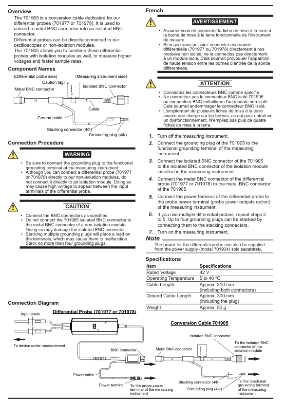
Model 701905 is a Yokogawa specific conversion cable that is only compatible with Yokogawa differential probes (models 701977 or 701978). Its core function is to convert the metal BNC connector of the differential probe into an insulated BNC connector, thereby achieving measurement in the following scenarios:
The differential probe could originally be directly connected to a Yokogawa oscilloscope or non insulated module, but after conversion from 701905, it can be used in conjunction with Yokogawa insulated modules.
After adapting to the insulation module, it can expand measurement capabilities, support signal measurement with higher voltage and faster sampling rate, and is suitable for insulation measurement scenarios such as power electronics and industrial control.
Packaging and accessory inspection
After opening the box, it is necessary to confirm that the following information is intact. If there are any model errors, missing accessories, or damaged appearance, please contact the Yokogawa dealer immediately:
Product/Document Name Model/Manual Number Quantity/Purpose
Conversion cable 701905 1 piece (core product)
Conversion Cable User Manual (English) IM 701905-01Z2 Volume 1 (this manual)
Chinese specific document IM 701905-92Z1 Volume 1 (Instructions for the Chinese market)
Global Contact List PIM 113-01Z2 Volume 1 (Yokogawa Global Office Contact Information)
Safety regulations
1. Core safety warning (to avoid electric shock/equipment damage)
Specific limitation: It can only be used in conjunction with Yokogawa differential probes (701977/701978) and Yokogawa insulation modules. It is prohibited to use it for other brands of equipment or non specified scenarios, otherwise it may cause high voltage hazards or equipment failures.
Grounding requirement: The grounding plug (4 Φ) of the cable must be connected to the functional grounding terminal of the measuring instrument. Failure to ground may result in measurement errors or safety hazards.
Prohibition of direct connection: Differential probes (701977/701978) can be directly connected to non insulated modules of Yokogawa, but direct connection to insulated modules is prohibited - otherwise high voltage may be generated between the input terminals of the differential probe, causing electric shock or equipment damage.
Connector matching: Only insulated BNC connectors of 701905 can be connected to insulated BNC connectors of insulated modules. It is forbidden to connect metal BNC connectors of non insulated modules to avoid damaging the insulated BNC interface.
2. Operation safety rules
Stacking restriction of grounding plugs: Multiple grounding plugs can be stacked through a "stacking connector (4 Φ)", but up to 4 can be stacked. Excessive stacking can cause load on the terminals, resulting in poor contact or terminal failure.
Operation sequence: Before connecting/disassembling, the power supply of the measuring instrument must be turned off to avoid short circuits or electric shocks caused by live operation; After the connection is complete, turn on the power to ensure safe wiring.
Pre reading of documents: Before use, it is necessary to read through the user manuals of the differential probe, measuring instrument, and insulation module, familiarize oneself with the rated parameters and operating limitations of each device.
Product Structure and Connection Process
1. Component name and function
Component Name Location (Differential Probe Side/Measuring Instrument Side) Function
Connect the metal BNC interface of the differential probe (701977/701978) on the differential probe side of the metal BNC connector to transmit signals
Insulated BNC connector connects the measuring instrument side to the insulated BNC interface of the insulation module on the measuring instrument, achieving insulation signal transmission
The signal transmission carrier in the middle part of the cable body includes shielding design to reduce interference
Grounding cable (GND cable): Connect the grounding plug and stacking connector on the measuring instrument side, with a length of approximately 300mm (including the plug)
Insert the grounding plug (4 Φ) into the functional grounding terminal of the measuring instrument on the measuring instrument side to ensure grounding safety
Stacking connector (4 Φ) next to the grounding plug is used to stack multiple grounding plugs (up to 4), suitable for multi probe scenarios
Pay attention to the safety warning information marked on the cable body of the solution tag, reminding users to follow the operating procedures
2. Standard connection process (single probe scenario)
Power off preparation: Turn off the power supply of the measuring instrument, ensure that all equipment is in a power-off state, and avoid live wiring.
Grounding connection: Insert the grounding plug of 701905 into the functional grounding terminal of the measuring instrument to ensure reliable grounding.
Connect the insulation module: Insert the insulation BNC connector of 701905 into the insulation BNC interface of the installed insulation module on the measuring instrument, and tighten it to avoid poor contact.
Connect differential probe: Insert the metal BNC connector of differential probe (701977/701978) into the metal BNC connector of 701905 to ensure smooth signal transmission path.
Power supply connection: Connect the power terminal of the differential probe to the probe power terminal of the measuring instrument (the measuring instrument needs to have the "probe power output" option); If the instrument does not have this terminal, a power supply (model 701934) sold separately by Yokogawa can be used for power supply.
Power on test: After confirming that all connections are correct, turn on the power of the measuring instrument and check if the signal transmission is normal.
3. Multi probe scenario (up to 4 differential probes)
If multiple differential probes need to be used simultaneously, repeat steps 2-5 above:
Each differential probe needs to be paired with one 701905 conversion cable.
The grounding plug is stacked through a "stacking connector" (up to 4) to ensure that each grounding plug is reliably grounded.
Technical specifications
Specification project specific parameter description
The rated voltage of 42 V needs to be used for a long time within the rated voltage range. Overvoltage may damage the insulation layer of the cable
The working temperature range of 5~40 ℃ may cause a decrease in cable performance and unstable signal transmission beyond this range
The total length of the cable is about 310 mm, including connectors at both ends, suitable for the wiring requirements of conventional measurement scenarios
The length of the grounding cable is about 300 mm, including the grounding plug, to ensure flexible wiring between the grounding terminal and the insulation module
Weight (including plug) about 50g, lightweight design reduces cable load during measurement, easy to operate
Maintenance and disposal
1. Daily maintenance
Appearance inspection: Before use, check whether the cable insulation layer is damaged, whether the connector is corroded or deformed. If there is any damage, stop using and contact Yokogawa for repair or replacement.
Cleaning: Use only a dry soft cloth to wipe the surface of the cable. Do not use solvents, alcohol, or abrasives to avoid damaging the insulation layer or connector coating.
Storage: When idle, the cable should be placed in a dry and ventilated environment, avoiding direct sunlight, high temperature, or humidity to prevent insulation layer aging.
2. Disposal of waste
When discarding, it is necessary to follow local laws and regulations, classify and dispose of cables and other electronic waste, and prohibit arbitrary disposal.
If the cable contains metal components (such as BNC connectors, grounding plugs), metal recycling can be carried out according to local regulations to reduce environmental impact.
- OMRON
- ABB
- General Electric
- EMERSON
- Honeywell
- HIMA
- ALSTOM
- Rolls-Royce
- MOTOROLA
- Rockwell
- Siemens
- Woodward
- YOKOGAWA
- FOXBORO
- KOLLMORGEN
- MOOG
- KB
- YAMAHA
- BENDER
- TEKTRONIX
- Westinghouse
- AMAT
- AB
- XYCOM
- Yaskawa
- B&R
- Schneider
- KONGSBERG
- NI
- WATLOW
- ProSoft
- SEW
- ADVANCED
- Reliance
- TRICONEX
- METSO
- MAN
- Advantest
- STUDER
- DANAHER MOTION
- Bently
- Galil
- EATON
- MOLEX
- DEIF
- B&W
- ZYGO
- Aerotech
- DANFOSS
- Beijer
- Moxa
- Rexroth
- Johnson
- WAGO
- TOSHIBA
- BMCM
- SMC
- HITACHI
- HIRSCHMANN
- Application field
- XP POWER
- CTI
- TRICON
- STOBER
- Thinklogical
- Horner Automation
- Meggitt
- Fanuc
- Baldor
- SHINKAWA
- Other Brands
- UniOP
- KUKA
- Iba
- Beckhoff
-
 Basler D90 96801 100 PCB Card
 -
 Basler XR2002F Voltage Regulator (110 VAC, 48-480 Hz)
 -
 Basler SR8A-2B14B3A Regulator
 -
 Basler 9561500100 Module
 -
 Basler DECS-400 BE1-11 System
 -
 Basler DECS-100-B15 Excitation Control
 -
 Basler SCP 210 Frequency Controller
 -
 Basler SR4A-2B15B3A Static Voltage Regulator
 -
 Basler BE1-32R Power Relay
 -
 Basler PIA2400-17GM Power Interface Adapter
 -
 Basler MVC 232 Manual Voltage Control Module
 -
 Basler SSR 32-12 Static Voltage Regulator
 -
 Basler 5MW AVR Generator Voltage Regulator
 -
 Basler VR63-4B Voltage Regulator
 -
 Basler DECS-100-A05 AVR for Engine Generator
 -
 Basler DECS-100-B15 Automatic Voltage Regulator
 -
 Basler BE1-32R Directional Power Relay
 -
 Basler BE1-87B Differential Relay
 -
 Basler UFOV 260A Protective Module
 -
 Basler 9-2614-02-100 PCB Rev M
 -
Basler DECS-100-B15 Digital AVR
-
 Basler 9284900103 PS DECS-400N
 -
 Basler D4N3H1U Intertie Protection
 -
 Basler DECS-100-B15 A15 AVR
 -
 Basler KR4F Voltage Regulator
 -
 Basler BE26434 T14 Transformer
 -
 Basler SR8A-2B15B3A Regulator
 -
 Westinghouse 774B472A12 AR Relay
 -
Basler DECS-100-B15 AVR
-
Basler XR2002F Regulator 110V
-
Basler SR125-E Static Regulator
-
 Basler SSR 125-12 Regulator
 -
 Basler MOC2599 Motor Pot
 -
 Basler BE1-DFPR Feeder Relay
 -
 Basler CBS 305 Current Boost
 -
 Basler BE1-25 AutoSync
 -
 Basler MVC 300 Voltage Control
 -
 Basler BE3-25A AutoSync
 -
 Basler KR7FF Static Regulator
 -
 Basler 90-49000-100 Regulator
 -
 Basler 880 kVA Dry Type Transformer Specs
 -
 Basler Electric BE1-25 Sync-Check Relay Specs
 -
 Basler SSR 125-12 Voltage Regulator Specs
 -
 Basler Electric BE1-851 Overcurrent Relay Review
 -
Basler Electric 149D930G02 Control Sub-Assembly
-
 Basler Electric BE1-81O/UT Frequency Relay Specs
 -
 Basler Electric BE1-51/27C Overcurrent Relay
 -
 Basler Electric 149D956G02 Industrial Component
 -
Basler Electric BE1-51A Overcurrent Relay Specs
-
 Basler Electric BE1-40Q Loss of Excitation Relay
 -
 Basler DECS-200 Excitation Control System
 -
 Basler DECS-200 Voltage Regulator 56-277V AC / 125V DC
 -
Basler BE1-87T Transformer Differential Relay
-
 Basler RDP-110-S1 Protection Relay
 -
 Basler BE1-700V Digital Protective Relay
 -
 Basler BE1-951 Overcurrent Protection System
 -
 Basler DECS-300 Digital Excitation Control
 -
 Basler DECS-200 Digital Excitation Control
 -
 Basler DECS-200-1C Excitation Control System
 -
Basler DECS-200-1L Digital Excitation Control
-
 Basler Electric BE1-GPS Generator Protection System
 -
Basler Electric DECS-200-1C Digital Excitation Controller
-
 Basler Electric DECS125-15 Excitation Control with Power Module
 -
 Basler Electric BE1-87G Differential Relay
 -
 Basler Electric BE1-11 Protection System I5A3M2P2N0EA00
 -
Basler Electric DECS-200-1C Excitation Control System
-
Basler Electric BE1-11g Generator Protection Relay
-
Basler Electric DECS 125-15-B2C1 V2.0.9 Excitation Control
-
 Basler Electric BE1-81O/UT3ED1JA7N2F Frequency Relay
 -
Basler Electric BE1-81O/UT3EE1YB7N1F Frequency Relay
-
 Basler Electric DECS-200-1L Digital Excitation Control System
 -
Basler DECS125-15-B2C1 Excitation Control
-
 Basler 9507900205 SSR Retrofit Voltage Regulator
 -
 Basler BE2000E Digital Voltage Regulator
 -
 Basler BE1-GPS Generator Protection System
 -
Basler DECS-250-CN1CN1N Digital Excitation Control
-
 Basler DGC-2020 Genset Controller
 -
 Basler BE1-81O UT3ED1LA7N0F Frequency Relay (Variant)
 -
 Basler BE1-81O UT3EE1YA9S0F Frequency Relay (Variant)
 -
Basler BE1-81O Over/Under Frequency Relay
-
Basler DECS125-15 Digital Excitation Control
-
Basler Electric BE1-951 Overcurrent Protection System
-
 Basler Electric BE1-700V Digital Protective Relay
 -
 Basler Electric APR63-5 Automatic Voltage Regulator
 -
Basler Electric BE1-851 Overcurrent Protection System
-
Basler Electric DECS-250-LN1SN1N Excitation Control
-
 Basler Electric BE1-87T Transformer Differential Relay
 -
Basler Electric DECS-200-1L Excitation Control System
-
 Basler Electric 9310300100 DECS-300 Excitation Control
 -
 Basler Electric SSE-N 125-4.5KW Shunt Exciter Regulator
 -
 Basler Electric DGC-2020HD-5NS1DNSBA Genset Controller
 -
Basler Electric BE1-81-O/UT3EE1JB7N1F Frequency Relay
-
Basler Electric BE1-81T1EE1WA0N1F Frequency Relay
-
 Basler Electric BE1-25M1EA6PN5R1F Sync-Check Relay
 -
 Basler Electric BE1-GPS Generator Protection System
 -
Basler Electric DECS-250-LN1SN1N Excitation Control Rev V
-
 Basler Electric DECS-250-CN2CN1N Excitation Control
 -
Basler Electric BE1-50/51B-207 Overcurrent Relay
-
Basler Electric DECS-300-C0N0 Excitation Control System
-
Basler Electric DECS-200 Digital Excitation Control System
-
Basler Electric DECS-250-LN1CN1N Excitation Unit
-
Basler Electric DECS-250 LN2SA1D Excitation Unit Specs
-
Basler Electric BE1-87T Transformer Relay Review
-
Basler Electric BE1-11 Protection System
-
Basler Electric BE1-GPS100-E4N1H1N Protection System
-
 Allen-Bradley 442G-MABH-R Safety Module
 -
 Beckhoff CX1030-0111 PLC Assembly Profile
 -
 FANUC IC693CPU364 PLC Module
 -
 Orange Denmark Type 200816 220 PLC Specs
 -
 OMRON C200H-SNT31 Sysmac PLC Module
 -
 Allen Bradley 20AB022A3AYNANC0 PowerFlex 70
 -
 OMRON C200HW-PCU01 Position Control Unit
 -
 ABB AO845A-eA Analog Output Module
 -
 OMRON CJ1M-CPU22 CPU Unit
 -
 Allen Bradley 100-E265ED11 Contactor
 -
 Honeywell 51304511-100 Interface Module
 -
 SOLEXY BXF3S0101N0018 Gateway Module
 -
 OMRON CJ2H-CPU65 CPU Unit
 -
 Automation Direct GS2-45P0 AC Drive
 -
 M68-2000 2-Axis Motion CNC Controller
 -
 OMRON CJ1M-CPU11 V3.0 PLC CPU Unit
 -
 OMRON CJ1W-NC413 4-Axis Positioning Controller
 -
 OMRON 3G2A3-PRO16 Programming Console HMI
 -
 Siemens 3VT8440-2AA04-2GA2 Molded Case Circuit Breaker
 -
 Siemens 3RT5045 Contactor Series
 -
 OMRON C200HS-CPU01-E SYSMAC PLC Controller
 -
 OMRON C500-NC103-E Positioning Control Unit
 -
 OMRON CJ1W-TC001 Temperature Control Unit


