Yokogawa Model 702928 PBD0200 Differential Probe
Core advantages: Bandwidth coverage from DC to 200MHz, excellent common mode rejection capability, and support for direct observation of differential signals; Equipped with a Yokogawa dedicated probe interface, it can automatically detect and supply power through the interface when connected to a compatible oscilloscope.
Applicable scenario: It needs to be used with an oscilloscope with a Yokogawa probe interface (specific compatible oscilloscope models can be consulted with Yokogawa distributors), suitable for signal measurement in industrial environments, and belongs to Class A products (may cause radio interference when used in residential areas, users need to solve it themselves)
Connect the probe head to the device under test, preheat for at least 30 minutes after powering on (the probe's own heating can cause offset voltage drift, which stabilizes after preheating), and adjust the offset voltage if necessary.
2. Key points for using accessories
Wire selection: A 10cm wire pair (including a 150 Ω damping resistor) is suitable for low-frequency signals, while a 5cm wire pair (including a 100 Ω damping resistor, sold separately) is more suitable for high-frequency signals; The crocodile clamp wire pair can directly clamp the measured point.
Pin selection: Spring type straight/bent pin (standard accessory), straight/bent pin (sold separately) suitable for high-frequency signals, need to be selected according to the pin position and status of the tested device.
Grounding extension cable: Only when measuring low-frequency signals, connect the probe grounding terminal to the common grounding of the tested equipment to reduce noise. It can be directly connected to a 0.64mm square or a Φ 0.65mm round pin.
3. Offset voltage adjustment
Adjustment timing: Adjust when there is still residual offset voltage after preheating, using an appropriate screwdriver (thickness 0.2-0.35mm, width 1.3-1.5mm, flat or cross).
Operation precautions: Do not apply excessive force to avoid damaging the internal variable resistor; Only used to adjust residual offset voltage, cannot be deliberately changed for other purposes, otherwise it may cause the probe to not meet specifications; Environmental temperature changes can affect offset voltage, and temperature should be taken into account during continuous measurements.
4. Custom extension cord production
Material preparation: Contact points, heat shrink tubing, flanged pins, fixed covers, and user provided wires (recommended AWG 24-26, maximum diameter 2.0mm) and damping resistors (optional) need to be purchased separately.
Production steps:
Thread the wire into the contact heat shrink tube, crimp/weld the wire core to the contact (connect in series when inserting the resistor), and heat the heat shrink tube to fix it.
The other end of the wire is threaded into the user's own heat shrink tubing and welded to the flanged pin. The heat shrink tubing is fixed (note that the tip of the pin cannot be welded within 4mm, and the diameter after heat shrink is ≤ 2.0mm).
Thread the flanges of the two input pins through the center hole of the fixed cover, align the probe head with the "+/-" mark, and install the fixed cover to ensure that the buckle is locked; Do not use the probe grounding terminal when using a fixed cover.

Product specifications
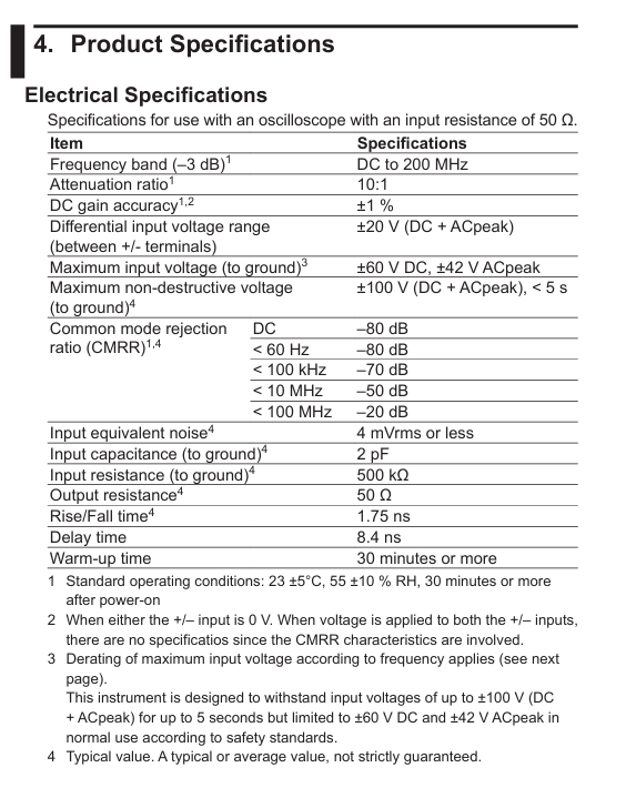
1. Electrical specifications (for use with a 50 Ω input resistance oscilloscope)
Project specifications
Frequency bandwidth (-3dB) DC to 200MHz
Attenuation ratio 10:1
DC gain accuracy (23 ± 5 ℃, preheating for 30 minutes+) ± 1% (when single ended input is 0V); Dual ended input without specifications due to CMRR characteristics
Differential input voltage range (+/- between terminals) ± 20V (DC+ACpeak)
Common mode rejection ratio (CMRR) DC: -80dB; <60Hz:-80dB; <100kHz:-70dB; <10MHz:-50dB; <100MHz: -20dB (typical value)
Input equivalent noise ≤ 4mVrms (typical value)
Input capacitance (to ground) 2pF (typical value)
Input resistance (to ground) 500k Ω (typical value)
Output resistance 50 Ω (typical value)
Rise/fall time 1.75ns (typical value)
Delay time 8.4ns
Preheating time ≥ 30 minutes
2. Input voltage derating (by frequency)
When the signal frequency increases, the maximum input voltage needs to be reduced, and the derating requirements of DC+ACpeak and ACpeak need to be met simultaneously:
Frequency maximum input voltage (DC+ACpeak) maximum input voltage (ACpeak)
DC~10MHz 60V 42V
10~151.6MHz decreases from 60V to 30V with increasing frequency, from 42V to 30V with increasing frequency
151.6~200MHz 30V 30V
3. General specifications and compliance
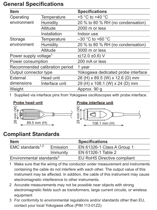
General specifications:
Project specifications
Power supply voltage ± (12.0 ± 0.6) V (powered by compatible oscilloscope interface pins)
Power consumption ≤ 200mA
Recommended calibration cycle of 1 year
Output connector type Yokogawa dedicated probe interface
Dimensions of the head unit: 26 (H) × 89.5 (W) × 12.6 (D) mm; Interface unit: 29 (H) × 108.1 (W) × 24 (D) mm
Weight approximately 90g
Compliance standards:
EMC standard: emission complies with EN 61326-1 Class A Group 1; The anti-interference degree complies with Table 2 of EN 61326-1 (note: strong electromagnetic field environments such as transformers, high current circuits, and near wireless devices may affect measurement accuracy).
Environmental standards: compliant with the EU RoHS directive; Environmental regulations in other regions require consultation with the local Yokogawa office.
Disposal: It is necessary to comply with the laws and regulations of the country/region where the product is disposed of; EU/UK must handle according to the WEEE directive and cannot mix with household waste. Contact the local Yokogawa office.

- ABB
- General Electric
- EMERSON
- Honeywell
- HIMA
- ALSTOM
- Rolls-Royce
- MOTOROLA
- Rockwell
- Siemens
- Woodward
- YOKOGAWA
- FOXBORO
- KOLLMORGEN
- MOOG
- KB
- YAMAHA
- BENDER
- TEKTRONIX
- Westinghouse
- AMAT
- AB
- XYCOM
- Yaskawa
- B&R
- Schneider
- Kongsberg
- NI
- WATLOW
- ProSoft
- SEW
- ADVANCED
- Reliance
- TRICONEX
- METSO
- MAN
- Advantest
- STUDER
- KONGSBERG
- DANAHER MOTION
- Bently
- Galil
- EATON
- MOLEX
- DEIF
- B&W
- ZYGO
- Aerotech
- DANFOSS
- Beijer
- Moxa
- Rexroth
- Johnson
- WAGO
- TOSHIBA
- BMCM
- SMC
- HITACHI
- HIRSCHMANN
- Application field
- XP POWER
- CTI
- TRICON
- STOBER
- Thinklogical
- Horner Automation
- Meggitt
- Fanuc
- Baldor
- SHINKAWA
- Other Brands


