
Yokogawa Model 702928 PBD0200 Differential Probe
Core advantages: Bandwidth coverage from DC to 200MHz, excellent common mode rejection capability, and support for direct observation of differential signals; Equipped with a Yokogawa dedicated probe interface, it can automatically detect and supply power through the interface when connected to a compatible oscilloscope.
Applicable scenario: It needs to be used with an oscilloscope with a Yokogawa probe interface (specific compatible oscilloscope models can be consulted with Yokogawa distributors), suitable for signal measurement in industrial environments, and belongs to Class A products (may cause radio interference when used in residential areas, users need to solve it themselves)
Yokogawa Model 702928 PBD0200 Differential Probe
Product positioning
Product type: Differential input active probe, model 702928 (PBD0200), needs to be used in conjunction with an oscilloscope for observing and measuring electrical signals, and cannot be used for other purposes.
Core advantages: Bandwidth coverage from DC to 200MHz, excellent common mode rejection capability, and support for direct observation of differential signals; Equipped with a Yokogawa dedicated probe interface, it can automatically detect and supply power through the interface when connected to a compatible oscilloscope.
Applicable scenario: It needs to be used with an oscilloscope with a Yokogawa probe interface (specific compatible oscilloscope models can be consulted with Yokogawa distributors), suitable for signal measurement in industrial environments, and belongs to Class A products (may cause radio interference when used in residential areas, users need to solve it themselves)
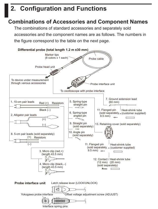
Packaging content and accessories
1. Standard Packaging List
Core equipment: differential probe unit (702928), portable case, supporting manual (see the "Supporting Manual" table above).
Standard accessories: The quantity and type of accessories are fixed, and standard accessories are not covered by the warranty of this instrument.
Number, accessory name, quantity
1 10cm wire pair (red/black) 2 sets
2 sets of crocodile clip wires (red/black)
3 micro clips (red,+) 1 piece
4 micro clips (black, -) 2 pieces
5 spring type straight needles, 4 pieces
6 spring type bent needles, 4 pieces
7 grounding extension wires, 2 pieces
2. Optional accessories (sold separately)
Additional accessories such as wires, pins, and fixed covers can be purchased. Some popular accessory information is as follows:
Number, accessory name, part number, quantity (single purchase specification)
1 10cm wire pair (red/black) B8099KU 5 sets
8 5cm wire pair (red/black) B8099KV 5 sets
9 straight needles B8099DL, 10 pieces
13 fixed covers B8099KY 2 pieces
Safety operation standards
1. Core Warning
Usage restrictions: Can only be used with oscilloscopes with Yokogawa probe interfaces, and it is necessary to confirm that the oscilloscope is labeled as "can connect to this probe"; Only use standard or official separately sold accessories.
Voltage limit: The maximum voltage between input and ground is ± 60V DC, ± 42V ACpeak; When the signal frequency increases, it needs to be derated for use (such as ACpeak maximum 30V at 200MHz, see "Product Specifications - Input Voltage derating" for details); The upper limit of non-destructive voltage for short-term (<5s) is ± 100V (DC+ACpeak), and normal use must comply with safety standard restrictions.
Connection sequence: When using, connect the oscilloscope first, and then connect the device under test; After use, disconnect the device under test first, then disconnect the oscilloscope, and ensure that the device under test is powered off when disconnecting.
Anti electric shock measures: Do not operate with wet hands or use the probe when it is damp; Avoid contact with exposed circuits and remove metal jewelry such as watches and rings before operation; Prohibited for use in flammable/explosive gas environments.
Troubleshooting: Stop using the probe immediately if suspected of damage (such as damaged signal lines or exposed metal), and contact the Yokogawa dealer; Disassembling or modifying the probe is prohibited, otherwise Yokogawa will not be held responsible.
2. Precautions (CAUTION)
Product features: Non dustproof and waterproof design, not suitable for use in dusty or near water environments; Not designed for long-term high reliability scenarios and not suitable for fields with extremely high stability requirements.
Environmental requirements: The operating/storage environment must comply with specifications (operating: 5-40 ℃, 20%~80% RH non condensing, altitude ≤ 2000m; storage: -30~60 ℃, 20%~80% RH non condensing, altitude ≤ 3000m), avoid direct sunlight, high temperature and humidity, or condensation to prevent deformation and insulation degradation.
Operation details: Wipe with a soft cloth during cleaning. Do not immerse the probe in liquids, and do not use abrasives or volatile solvents such as benzene; Avoid vibration, impact, and static electricity during operation, and do not excessively bend/pull cables.
Grounding requirements: The oscilloscope protection grounding terminal must be grounded; When measuring floating circuits, grounding terminals should not be used, only common grounding should be used, otherwise it may damage the measurement system or the tested equipment.
Usage method
1. Operation process
Prepare the probe and compatible oscilloscope, match accessories (such as wires and pins) according to the tested device and environment, and connect them to the probe head signal input terminal.
Insert the probe output connector into the oscilloscope input terminal and install it in place upon hearing the locking sound; The oscilloscope will automatically detect the probe and set the input coupling. If it is not set automatically, it will be manually adjusted.
Connect the probe head to the device under test, preheat for at least 30 minutes after powering on (the probe's own heating can cause offset voltage drift, which stabilizes after preheating), and adjust the offset voltage if necessary.
2. Key points for using accessories
Wire selection: A 10cm wire pair (including a 150 Ω damping resistor) is suitable for low-frequency signals, while a 5cm wire pair (including a 100 Ω damping resistor, sold separately) is more suitable for high-frequency signals; The crocodile clamp wire pair can directly clamp the measured point.
Pin selection: Spring type straight/bent pin (standard accessory), straight/bent pin (sold separately) suitable for high-frequency signals, need to be selected according to the pin position and status of the tested device.
Grounding extension cable: Only when measuring low-frequency signals, connect the probe grounding terminal to the common grounding of the tested equipment to reduce noise. It can be directly connected to a 0.64mm square or a Φ 0.65mm round pin.
3. Offset voltage adjustment
Adjustment timing: Adjust when there is still residual offset voltage after preheating, using an appropriate screwdriver (thickness 0.2-0.35mm, width 1.3-1.5mm, flat or cross).
Operation precautions: Do not apply excessive force to avoid damaging the internal variable resistor; Only used to adjust residual offset voltage, cannot be deliberately changed for other purposes, otherwise it may cause the probe to not meet specifications; Environmental temperature changes can affect offset voltage, and temperature should be taken into account during continuous measurements.
4. Custom extension cord production
Material preparation: Contact points, heat shrink tubing, flanged pins, fixed covers, and user provided wires (recommended AWG 24-26, maximum diameter 2.0mm) and damping resistors (optional) need to be purchased separately.
Production steps:
Thread the wire into the contact heat shrink tube, crimp/weld the wire core to the contact (connect in series when inserting the resistor), and heat the heat shrink tube to fix it.
The other end of the wire is threaded into the user's own heat shrink tubing and welded to the flanged pin. The heat shrink tubing is fixed (note that the tip of the pin cannot be welded within 4mm, and the diameter after heat shrink is ≤ 2.0mm).
Thread the flanges of the two input pins through the center hole of the fixed cover, align the probe head with the "+/-" mark, and install the fixed cover to ensure that the buckle is locked; Do not use the probe grounding terminal when using a fixed cover.
Product specifications
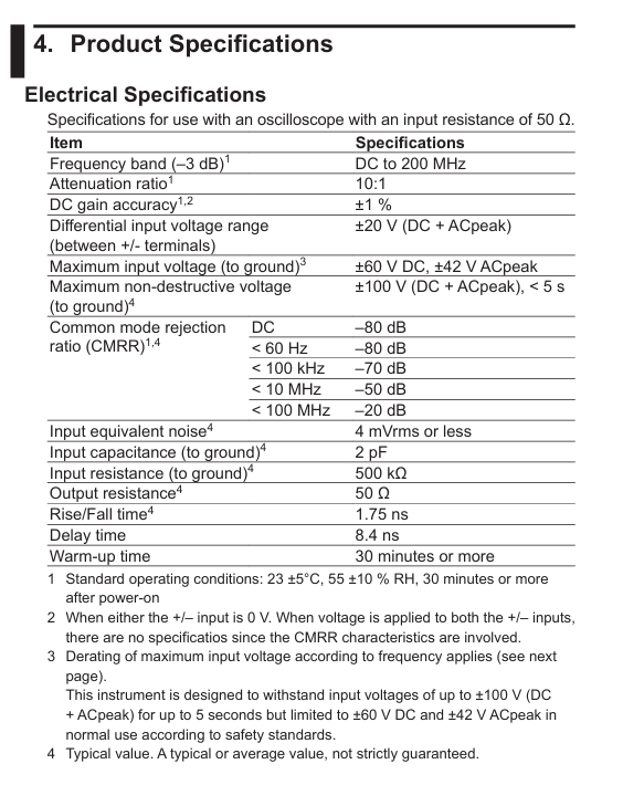
1. Electrical specifications (for use with a 50 Ω input resistance oscilloscope)
Project specifications
Frequency bandwidth (-3dB) DC to 200MHz
Attenuation ratio 10:1
DC gain accuracy (23 ± 5 ℃, preheating for 30 minutes+) ± 1% (when single ended input is 0V); Dual ended input without specifications due to CMRR characteristics
Differential input voltage range (+/- between terminals) ± 20V (DC+ACpeak)
Common mode rejection ratio (CMRR) DC: -80dB; <60Hz:-80dB; <100kHz:-70dB; <10MHz:-50dB; <100MHz: -20dB (typical value)
Input equivalent noise ≤ 4mVrms (typical value)
Input capacitance (to ground) 2pF (typical value)
Input resistance (to ground) 500k Ω (typical value)
Output resistance 50 Ω (typical value)
Rise/fall time 1.75ns (typical value)
Delay time 8.4ns
Preheating time ≥ 30 minutes
2. Input voltage derating (by frequency)
When the signal frequency increases, the maximum input voltage needs to be reduced, and the derating requirements of DC+ACpeak and ACpeak need to be met simultaneously:
Frequency maximum input voltage (DC+ACpeak) maximum input voltage (ACpeak)
DC~10MHz 60V 42V
10~151.6MHz decreases from 60V to 30V with increasing frequency, from 42V to 30V with increasing frequency
151.6~200MHz 30V 30V
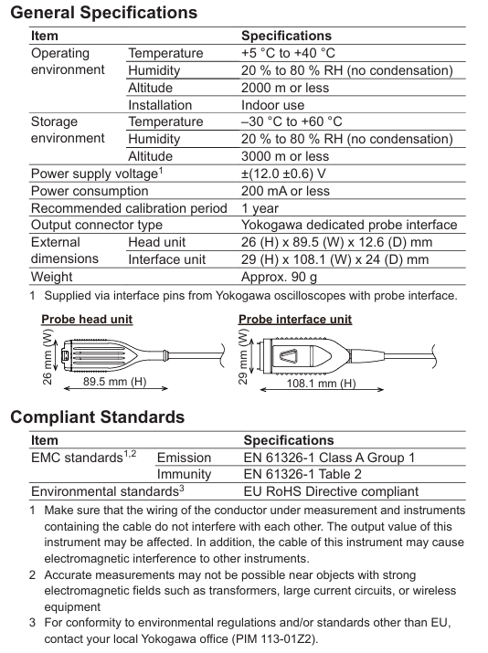
3. General specifications and compliance
General specifications:
Project specifications
Power supply voltage ± (12.0 ± 0.6) V (powered by compatible oscilloscope interface pins)
Power consumption ≤ 200mA
Recommended calibration cycle of 1 year
Output connector type Yokogawa dedicated probe interface
Dimensions of the head unit: 26 (H) × 89.5 (W) × 12.6 (D) mm; Interface unit: 29 (H) × 108.1 (W) × 24 (D) mm
Weight approximately 90g
Compliance standards:
EMC standard: emission complies with EN 61326-1 Class A Group 1; The anti-interference degree complies with Table 2 of EN 61326-1 (note: strong electromagnetic field environments such as transformers, high current circuits, and near wireless devices may affect measurement accuracy).
Environmental standards: compliant with the EU RoHS directive; Environmental regulations in other regions require consultation with the local Yokogawa office.
Disposal: It is necessary to comply with the laws and regulations of the country/region where the product is disposed of; EU/UK must handle according to the WEEE directive and cannot mix with household waste. Contact the local Yokogawa office.
- OMRON
- ABB
- General Electric
- EMERSON
- Honeywell
- HIMA
- ALSTOM
- Rolls-Royce
- MOTOROLA
- Rockwell
- Siemens
- Woodward
- YOKOGAWA
- FOXBORO
- KOLLMORGEN
- MOOG
- KB
- YAMAHA
- BENDER
- TEKTRONIX
- Westinghouse
- AMAT
- AB
- XYCOM
- Yaskawa
- B&R
- Schneider
- KONGSBERG
- NI
- WATLOW
- ProSoft
- SEW
- ADVANCED
- Reliance
- TRICONEX
- METSO
- MAN
- Advantest
- STUDER
- DANAHER MOTION
- Bently
- Galil
- EATON
- MOLEX
- DEIF
- B&W
- ZYGO
- Aerotech
- DANFOSS
- Beijer
- Moxa
- Rexroth
- Johnson
- WAGO
- TOSHIBA
- BMCM
- SMC
- HITACHI
- HIRSCHMANN
- Application field
- XP POWER
- CTI
- TRICON
- STOBER
- Thinklogical
- Horner Automation
- Meggitt
- Fanuc
- Baldor
- SHINKAWA
- Other Brands
- UniOP
- KUKA
- Iba
- Beckhoff
- ADLINK
-
 Basler Electric BE1-700 Digital Protective Relay
 -
 Basler Electric SR8A-2B01B3A Static Voltage Regulator
 -
 Basler Electric SR4A-2B01B3E Static Voltage Regulator
 -
 Basler Electric 9017709102 PC Board
 -
Basler Electric SR4A-2B01B3A Static Voltage Regulator
-
 Basler Electric PRS-250 Veri-Sync Relay
 -
 Basler Electric 9066800102 Excitation Support System
 -
 Basler Electric BE1-87G Generator Differential Relay 9 1708 18 100
 -
 Basler Electric 36T865-2 BE03752001 Power Supply
 -
 Basler Electric M-300 149D940G02 Power Supply
 -
 Basler Electric ACA2040-25GM 4Mp 25Fps Area Scan Camera
 -
 Basler BE1-87G-S1A-A1C-A0N0 Differential Relay
 -
 Basler SR8A-2B06B3E Static Regulator SR8A2B06B3E
 -
 Basler SCP-210 Frequency Controller 9095400100
 -
 Basler BE1-59-A3E-A1J-N1N3F Overvoltage Relay BE159A3EA1JN1N3F
 -
 Basler 9 2011 11 100 Bracket Mounted Terminal Unit
 -
Basler 9 1606 00 101 Voltage Regulator
-
 Basler CBS-377 Current Boost System 9109600102
 -
 Basler 8650C72 Exciter Control Module PCB Rev 5
 -
 Basler C2EE1PA0N1F BE1-32R Reverse Power Relay
 -
 ADLINK HPCI-14S12U - Industrial Control Backplane 12PCI Backplane PCI-14S Passive Backplane
 -
-0010.png) ADLINK PCIe-GIE74C - image acquisition card 4-CH GigE Vision PoE+ Frame Grabber
ADLINK PCIe-GIE74C - image acquisition card 4-CH GigE Vision PoE+ Frame Grabber -
-0010_1.png) ADLINK PCI-8164 - control card 4-Axis Advanced Motion Controller Board
ADLINK PCI-8164 - control card 4-Axis Advanced Motion Controller Board -
 ADLINK PCIe-U304 - 4 Port USB3 PCIe Frame Grabbers USB Screw Hole Card
 -
 ADLINK PCI-9112 - Multi-Function Data Acquisition Card DAQ Card
 -
 ADLINK PCI-7432 - 51-12013-0A50 4-CH Isolated Numérique I/O PCI Cartes Digital I/O Card
 -
 ADLINK PCA-6106P3-0C1 REV.C1 - backplane 6-Slot Passive Backplane Board
 -
 ADLINK PCI-7224 - 24-CH Opto-Isolated Digital I/O PCI Board
 -
 ADLINK CPCI-7433R(G) - Digital Input Board Rear I/O CompactPCI Card
 -
 ADLINK EBP-13E4 - 51-46703-0A30 Industrial PC Backplane Passive Backplane
 -
 ADLINK PCIE-HDV62 - Image acquisition card High Definition Video Frame Grabber
 -
 ADLINK EBP-13E4 - 51-46703-0A30 Industrial Backplane Board Passive Backplane
 -
 ADLINK 90111-B1 / CPCI-6770 - PCB CPU MODULE CompactPCI Single Board Computer
 -
 ADLINK PCI-7248 - DATA ACQUISITION PCI CARD 48-CH Parallel Digital I/O Board
 -
 ADLINK PCI-7230 - 51-12003-0a50 board PCI7230 32-CH Isolated Digital I/O Card
 -
 ADLINK PCI2A000CB - 51-20000-0B30 Multi-Function DAQ Card Baseboard
 -
 ADLINK PCI-8134-005 - 4-Axis Motion Controller Card
 -
 ADLINK PCI-7224 - 24-CH Opto-Isolated Digital I/O PCI Card
 -
 ADLINK PCI-7434 - 64-CH Isolated Digital Output Card
 -
 ADLINK PCI-8132 - motion control card 2-Axis Servo & Stepper Controller
 -
 ADLINK PCI-8134 - Motion Controller PCI Card 4-Axis Controller Board
 -
 ADLINK PCI-8164 - Motion Control Card 51-12406-0A40 4-Axis Controller
 -
 ADLINK 51-12001-0C20 - Circuit Board Data Acquisition Interface Module Hardware
 -
 ADLINK NuPR0-840 - industrial control motherboard Full-Size PICMG CPU Board
 -
 ADLINK PCI-7444 - 51-12023-0A10 card 128-CH Isolated Digital Output Board
 -
 ADLINK PCI-1612B - data acquisition card 4-Port RS-232/422/485 Serial Communication Card
 -
 ADLINK PCI-6208V 009 - 8/16-CH 16-Bit Analog Output Cards PCB-I-E-482=6BX3
 -
 ADLINK NUPRO-935A/LV - industrial control motherboard Full-Size PICMG SBC Board
 -
 ADLINK PCI-9114DG - Multi-Function DAQ Card Data Acquisition PCI Card
 -
 ADLINK ACL-7130 - Data acquisition card Isolated Digital I/O Board
 -
 ADLINK ABX-6300D-4E1-BP - board ABX6300D4E1BP Video Interface Expansion Card
 -
 ADLINK CPCI-6940 - CPCI-6940/D1539/M16-0(EA)-000E 6U CompactPCI Processor Board
 -
 ADLINK NuPRO-760 - industrial control motherboard Half-Size PICMG SBC CPU Board
 -
 ADLINK IMB-M42H (G)-0020 - industrial control motherboard LGA1155 Micro-ATX Mainboard
 -
 ADLINK RTV-24 / PCI-MP4S - 51-12519-1C30 4-Channel Real Time Video Capture Board
 -
 ADLINK PCI-8134 - 4-Axis Servo & Stepper Motion Controller Card
 -
 ADLINK MXC-6101D - V.PC000.002.ST.00 Box PC Configurable Embedded Computer
 -
.png) ADLINK PCI-8134A - 51-12421-0A10 Motion Control Card 4-Axis Controller Card
ADLINK PCI-8134A - 51-12421-0A10 Motion Control Card 4-Axis Controller Card -
 ADLINK DIN-100S / DIN-100SA1 - Technology SCSI-II TB 100-PIN Terminal Block Board
 -
.png) ADLINK DIN-812M001 / DIN812M001 - 51-14034-0A1 51140340A1 Terminal Module Breakout Interface
ADLINK DIN-812M001 / DIN812M001 - 51-14034-0A1 51140340A1 Terminal Module Breakout Interface -
_1.png) ADLINK PCI-8164 - Servo motion control 4-Axis Advanced Controller Card
ADLINK PCI-8164 - Servo motion control 4-Axis Advanced Controller Card -
 ADLINK PCIe-GIE64 - Acquisition card GigE Vision PoE+ Frame Grabber
 -
 ADLINK M-302 - Industrial control motherboard ATX PC Board Mainboard
 -
 ADLINK PCI-8134 - Motion Controller PCI Card 4-Axis Controller Board
 -
 ADLINK PCI-RTV24 - Image capture card Analog Video Frame Grabber
 -
 ADLINK PCI-8102 - Motion control card 2-Axis Servo & Stepper Controller Board
 -
 ADLINK PCI-9112 REV.B1 - Card Multi-Function Data Acquisition Card
 -
 ADLINK HSI-DI32-M-N / HSL-TB32-M-DIN - Discrete I/O MODULE Distributed Automation Module System
 -
 ADLINK PCI-7296 - IO card REV.A3 96-CH Parallel Digital I/O Card
 -
-0020.png) ADLINK DIN-814P-A4 / 814Y - terminal board Motion Control Interface Block
ADLINK DIN-814P-A4 / 814Y - terminal board Motion Control Interface Block -
 ADLINK DIN-814P-A4 - 51-14056-0A10 PCB-I-E-2736=ZA01 Screw Terminal Board Breakout
 -
 ADLINK M-322 - motherboard Industrial Control Computer Mainboard
 -
 ADLINK NUPRO-406 REV:B1 - industrial control motherboard Full-Size PICMG CPU Board
 -
 ADLINK AMP-204C - card DSP-Based 4-Axis Advanced Pulse-Train Controller
 -
 ADLINK HPCI14S REV.B1 - industrial computer baseboard 14-Slot Passive Backplane
 -
 ADLINK PCI-7250 - 8-CH Relay Output & 8-CH Isolated DI PCI Card
 -
 ADLINK EBP-13E2 - baseplate Passive Backplane Industrial Computer Chassis Board
 -
 ADLINK LPCI-3488A - PCI-GPIB card 51-12801-0A30 acquisition card IEEE-488 Interface Board
 -
 ADLINK PCI-6216V-GL - 51-12201-0C30 16-CH 16-Bit Voltage Analog Output Card
 -
 ADLINK ACL-8454 - 16-CH Isolated Digital I/O & 4-CH Counter Card
 -
 ADLINK HPCI-9S7U - backplane Passive Backplane Compatible with NuPRO-A301 852 841 842
 -
 ADLINK DAQ-2010-007 - Simultaneous-Sampling Multi-Function Data Acquisition Card
 -
 ADLINK MP-C154 - 51-64205-0A10 Motion Control Card 4-Axis Controller Board
 -
 ADLINK MXE-202/mSSD16B/WiFi-BT - Matrix Rugged I/O Platform Embedded Fanless Computer
 -
 ADLINK CM-920-R-17 - PC/104-Plus Single Board Computer Module Intel Celeron M
 -
 ADLINK PCI-7250 NSMP - 8-CH Relay Output & 8-CH Isolated DI Card
 -
 ADLINK PCI-8164 - 4-Axis Motion Controller PCI Card W/ Cable and Breakout Box
 -
 ADLINK EMX-100 - Ethernet-based 4-axis Motion Controllers Distributed Motion Module
 -
.png) ADLINK PCI-8134A - Press control card 4-Axis Motion Controller Board
ADLINK PCI-8134A - Press control card 4-Axis Motion Controller Board -
 ADLINK M-845EG REV:3.2 - industrial motherboard Pentium 4 Socket 478 Micro-ATX
 -
 ADLINK PCI-9114A Rev A2 DG - card High-Resolution Multi-Function Data Acquisition Board
 -
 ADLINK IEC-915GV - REV 1.1 Industrial motherboard Socket 478 CPU Board
 -
 ADLINK PCI-9111DG(G) - Data Acquisition Card Multi-Function DAQ Card
 -
 ADLINK HPCI-15S10 REV:B2 - Industrial computer base plate Passive Backplane Board
 -
 ADLINK NuPR0-840 / NuPR0-840DV - industrial control motherboard Full-size PICMG CPU Board
 -
 ADLINK RTV-24 / PCI-MP4S - 51-12519-1C30 4-Channel Real Time Video Capture Board
 -
 ADLINK NUPRO-780 - industrial control motherboard Pentium III Single Board Computer
 -
 ADLINK PCI-7296 - 0050 card 96-CH Opto-Isolated Parallel DIO Card Set
 -
-0040.png) ADLINK NUPRO-780 - industrial control motherboard PICMG Full-Size SBC
ADLINK NUPRO-780 - industrial control motherboard PICMG Full-Size SBC -
 ADLINK PCI-7248 - 51-12006-0A3 002 Pci 7248 48-CH Parallel Digital I/O Card
 -
 ADLINK PCI-7230 - 32-CH Isolated Digital I/O Card
 -
 ADLINK AMP-204C - motion control card 4-Axis Advanced Controller Board
 -
.png) ADLINK PCI-1714UL - Card Ultra High-Speed 4-CH Simultaneous Sampling DAQ
ADLINK PCI-1714UL - Card Ultra High-Speed 4-CH Simultaneous Sampling DAQ -
 ADLINK NuPRO-E330 - industrial computer equipment motherboard PICMG 1.3 SHB SBC
 -
 ADLINK AMP-204C - DSP-Based 4-Axis Advanced Pulse-Train Motion Controller Module
 -
 ADLINK PCI-7256 - 001 51-12206-0A2 REV.A2 LPCI-7256 16-CH Latching Relay Output Card
 -
 ADLINK ND6050 - NUDAM DIGITAL I/0 MODULE Distributed I/O Unit
 -
 ASEM BM100 - Box PC Embedded Fanless Industrial Computer
 -
-3650.png) ADLINK PCI-7250 - PCI Acquisition Card 8-CH Relay Output & Isolated DI Board
ADLINK PCI-7250 - PCI Acquisition Card 8-CH Relay Output & Isolated DI Board -
 ADLINK PCI-8164 - Servo motion control 4-Axis Controller Card
 -
 ADLINK NuPRO-A40H - Industrial Motherboard 51-41807-1A30 OSP LGA1155 H61
 -
 ADLINK ADMAX X300 SERVER - 51066010-0A30 motherboard Multi-Processor Mainboard
 -
 ADLINK CMe-GIE62+ - 51-32903-0A30 control card PC/104-Plus GigE Vision Frame Grabber
 -
 ADLINK NUPRO-780 - industrial control motherboard Full-Size PICMG SBC CPU Board
 -
 ADLINK ETX-AT-N270-18/GKTEL - 51-71111-OB10 motherboard ETX CPU Module Board
 -
 ADLINK DIN-812M - interface module Terminal Block Connection Board
 -
 ADLINK IMB-M42H - industrial control motherboard LGA1155 Micro-ATX Mainboard
 -
ADLINK PXIS-2508 - 8-slot 3U PXI Instrument Chassis Power Hardware Assembly
-
ADLINK AMP-208C - Motion Control card DSP-Based 8-Axis Pulse-Train Controller
-
ADLINK PCI-9111 / PCI-9111DG - Multi-Function Data Acquisition Card DAQ Board
-
ADLINK IEEE-488 GPIB card - Bus Interface Controller Communication Board
-
ADLINK RTV-24 - 51-12519-1C30 image acquisition card Video Frame Grabber Card
-
ADLINK TB-24P/24-01 - Board 24 Way Screw Terminal Breakout Board
-
ADLINK HSL-DI16DO16-DB-NN - 51-23015-0A40 Distributed Discrete I/O Module Set
-
ADLINK PCI-7442 - switch quantity card data acquisition card 64-CH Isolated Card
-
ADLINK ACL-7130 REV. B2 - industrial control capture card Isolated Digital I/O PCI Card
-
ADLINK PCI-6S / PCI6S - Backplane 6-Slot Passive Backplane Chassis Board
-
ADLINK ACL-8113A - card Isolated Digital Input Card


