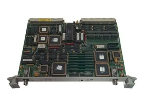
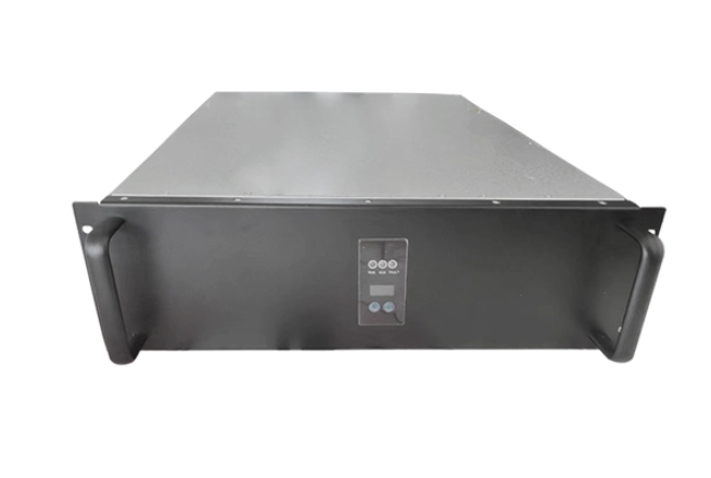
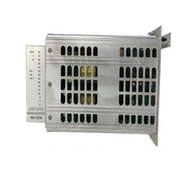
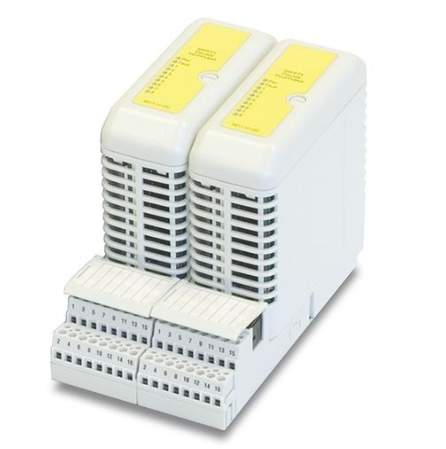
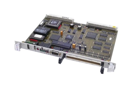
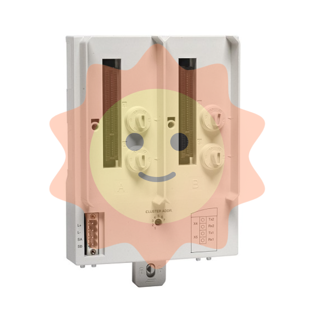
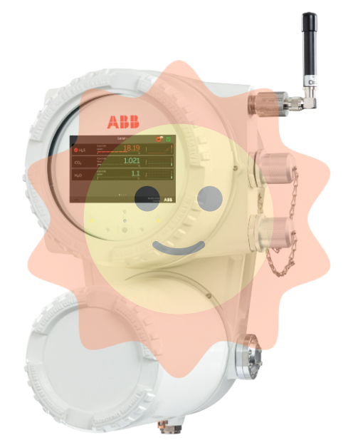
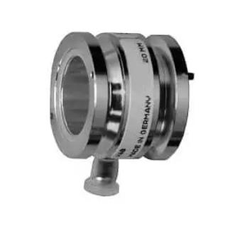
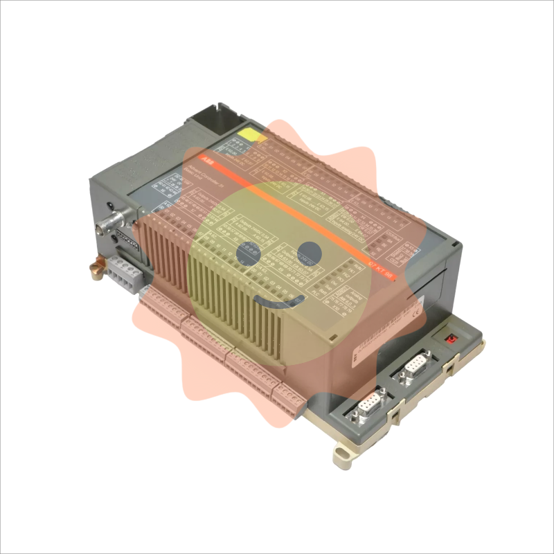
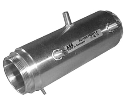
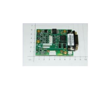
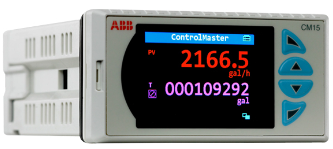
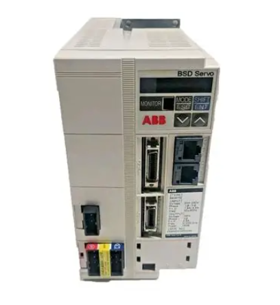
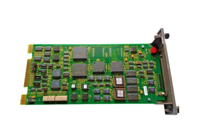
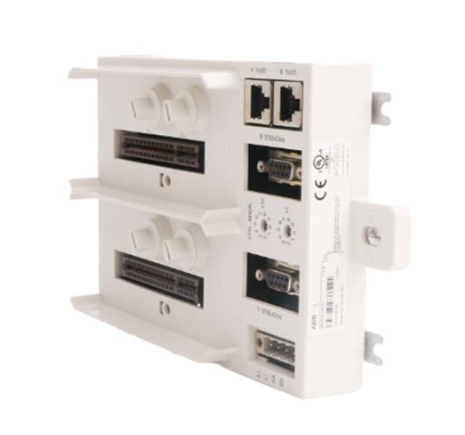
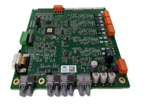
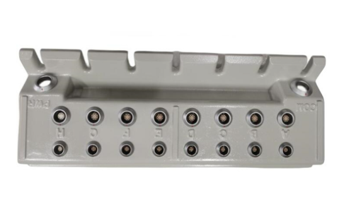
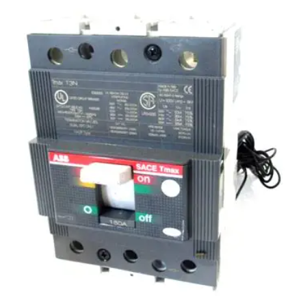
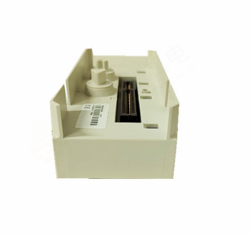
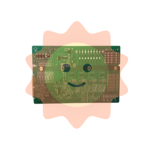
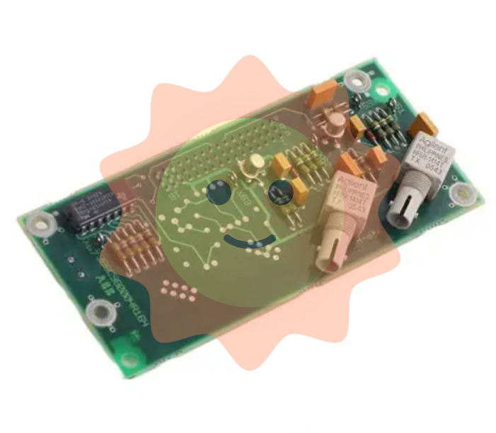
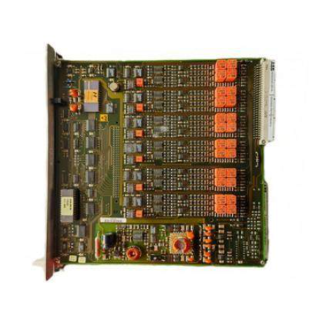
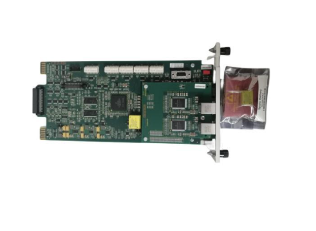
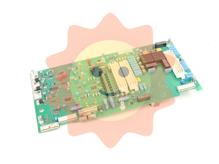
ABB AO2040-CU Ex Central Unit
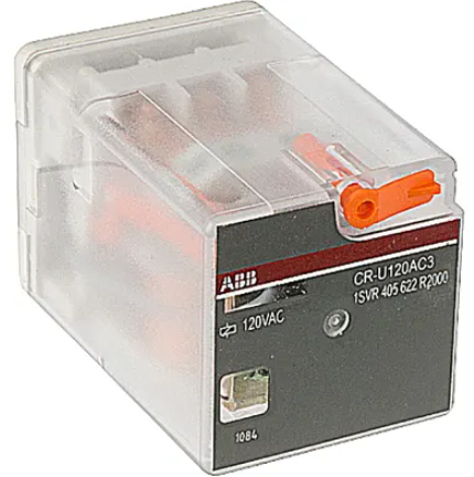
Electrical equipment composition: including isolation relays, terminal blocks, line filters, pressurized enclosure system control units, isolation amplifiers, etc.
Each device has its specific functions and connection requirements.
Analysis module connection: The system bus and 24VDC cable are components of the pressurized enclosure system, with a length of not less than 1 meter; Connect the system bus cable and 24VDC cable to the central unit according to the steps.
Non intrinsic safety signal line connection: connected to the right side of the isolation relay; The intrinsic safety signal circuit of the condensate monitor is connected through a bright blue cable, with a total length not exceeding 75 meters, and a 100k Ω resistor is installed next to the sensor.
Status signal, potential compensation and power connection: The minimum cross-sectional area of the conductor for potential compensation connection is 4mm ²; Connect the status signal to control unit terminals 21 and 22; Before connecting the power supply, confirm that the voltage settings match, install appropriate protective devices and easy to operate circuit breakers, and connect control unit terminals 15, 17 and PE terminals.
Operation and maintenance
Pre start inspection: Confirm that the installation site conditions, equipment installation firmness, suppression of gas flow, shell integrity, electrical circuit connections, etc. meet the requirements.
Startup steps: Connect the power supply and suppress the gas supply. After the initial purge is completed, switch the solenoid valve to "leakage compensation" and activate the power supply of the equipment inside the system casing; After startup, the "Power", "Maintenance", and "Error" LEDs light up, and the screen displays the startup phase and software version, then switches to measurement mode.
Maintenance bypass operation: When there is no explosive environment, the bypass of the pressurized shell system control unit can be activated, which requires approval from the operations manager; Activate and deactivate the bypass according to the steps, and the bypass must be deactivated during normal operation.
Regular inspection: Conduct routine checks according to the pre startup checklist.
Appendix: Application and Design
Application and Design Overview: Used in conjunction with the AO2060 series analysis module to control and monitor the measurement and control process; The system casing is wall mounted and designed to comply with EN 60079-2 "pressurized casing with leakage compensation"; Can access intrinsic safety and non intrinsic safety signal circuits, and the system controller has no battery backup.
Pressure shell system: using air that complies with ISO 8573-1 Level 3 as the suppression gas, with a particle trap at the outlet; Perform preliminary blowdown set by the factory during startup, and maintain a positive pressure of approximately 2hPa inside the system casing during operation; When the positive pressure is lower than 0.8hPa or higher than 15hPa, disconnect the power supply and isolation relay connection circuit of the equipment inside the system casing, and after the pressure is restored, blow and activate again; When the internal pressure is below 1.2hPa, a status signal is output through passive relay contacts.

- EMERSON
- Honeywell
- CTI
- Rolls-Royce
- General Electric
- Woodward
- Yaskawa
- xYCOM
- Motorola
- Siemens
- Rockwell
- ABB
- B&R
- HIMA
- Construction site
- electricity
- Automobile market
- PLC
- DCS
- Motor drivers
- VSD
- Implications
- cement
- CO2
- CEM
- methane
- Artificial intelligence
- Titanic
- Solar energy
- Hydrogen fuel cell
- Hydrogen and fuel cells
- Hydrogen and oxygen fuel cells
- tyre
- Chemical fiber
- dynamo
- corpuscle
- Pulp and paper
- printing
- fossil
- FANUC
- Food and beverage
- Life science
- Sewage treatment
- Personal care
- electricity
- boats
- infrastructure
- Automobile industry
- metallurgy
- Nuclear power generation
- Geothermal power generation
- Water and wastewater
- Infrastructure construction
- Mine hazard
- steel
- papermaking
- Natural gas industry
- Infrastructure construction
- Power and energy
- Rubber and plastic
- Renewable energy
- pharmacy
- mining
- Plastic industry
- Schneider
- Kongsberg
- NI
- Wind energy
- International petroleum
- International new energy network
- gas
- WATLOW
- ProSoft
- SEW
- wind
- ADVANCED
- Reliance
- YOKOGAWA
- TRICONEX
- FOXBORO
- METSO
- MAN
- Advantest
- ADVANCED
- ALSTOM
- Control Wave
- AB
- AMAT
- STUDER
- KONGSBERG
- MOTOROLA
- DANAHER MOTION
- Bently
- Galil
- EATON
- MOLEX
- Triconex
- DEIF
- B&W
- ZYGO
- Aerotech
- DANFOSS
- KOLLMORGEN
- Beijer
- Endress+Hauser
- MOOG
- KB
- Moxa
- Rexroth
- YAMAHA
- Johnson
- Westinghouse
- WAGO
- TOSHIBA
- TEKTRONIX


Email:wang@kongjiangauto.com

