
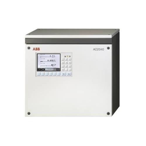
ABB AO2040-CU Ex Central Unit
ABB AO2040-CU Ex Central Unit
The specialized operating guide for ABB AO2040-CU Ex central unit (2G class) serves as a supplement to the main operating manual for the AO2000 series continuous gas analyzer (publication number 42/24-10 EN), containing key information for safe installation, start-up, and operation of the equipment. The "Analyzer Data Sheet" accompanying each device should be used in conjunction with this manual. The symbols "1, 2, 3,..." in the manual indicate safety operation points, and the symbol "●" indicates specific instructions for equipment operation.
Technical Parameter
Compliant with standards: Compliant with DMT 08 ATEX 2018 U 605 standard, explosion-proof mark Ex de IIC T4 Gb, equipment category 2G, suitable for use in Zone 1 and Zone 2 explosion hazardous areas.
Size and weight: The equipment size is not explicitly mentioned, with a weight of approximately 28kg.
Suppress gas related parameters
Gas type: Use air that meets ISO 8573-1 standard level 3 as the suppression gas.
Gas quality requirements: maximum particle size of 40 μ m, maximum oil content of 1mg/m ³, maximum pressure dew point+3 ° C.
Working pressure range: Suppress gas working pressure to 250-500kPa (2.5-5bar).
Power supply parameters
Voltage setting: Before connecting to the power supply, it is necessary to confirm that the equipment voltage setting matches the line voltage. The specific voltage setting value is not explicitly mentioned.
Power protection device: Install suitable protection devices and easy to operate circuit breakers, specific specifications are not explicitly mentioned.
Pressure parameters
Positive pressure inside the system casing: Maintain a positive pressure of approximately 2hPa inside the system casing during operation.
Positive pressure alarm and protection threshold: When the positive pressure is below 0.8hPa or above 15hPa, disconnect the power supply and isolation relay connection circuit inside the system enclosure; When the internal pressure is below 1.2hPa, a status signal is output through passive relay contacts.
Electrical connection parameters
Potential compensation connection: External potential compensation connection or protective wire with a minimum cross-sectional area of 4mm ².
Intrinsic safety signal circuit: The total length of the intrinsic safety signal circuit for the condensate water monitor shall not exceed 75 meters, and a 100k Ω resistor shall be installed next to the sensor.
Cable connector specification: M20 threaded connector is suitable for cable outer diameters of 6-12mm.
Safety operation information
General safety requirements: The equipment must be properly handled, stored, installed, set up, operated, and maintained; Only personnel who are familiar with similar equipment and have relevant qualifications can operate it; It is necessary to comply with the content of this manual, equipment safety information, safety precautions for electrical equipment and gas operation, as well as explosion-proof regulations and standards.
Special safety instructions: Follow all explosion-proof safety measures before operation; Do not operate current carrying components in explosive risk environments except for intrinsically safe circuits; Connect the local potential compensation point first; Ensure that the equipment voltage setting matches the line voltage; Before opening the casing, disconnect all power sources and wait for 10 minutes for the power capacitor to discharge; If the equipment is damaged, unable to operate, or has poor storage and transportation conditions, it should be stopped from use.
Installation guide
Unpacking and installation: The equipment weighs approximately 28kg and requires two people to operate. The installation position should be stable; Can be installed in Zone 1 and Zone 2 explosion hazardous areas, and cannot be installed outdoors.
Suppression gas pipeline connection: Use air that complies with ISO 8573-1 Level 3 as the suppression gas; Install the accompanying compressed air conditioning filter to prevent valve damage caused by gas pipeline contamination.
Electrical connection safety precautions: Do not change the internal wiring of the factory, only modify the wiring between the isolation relay and the system controller and I/O board connectors; First, connect the external potential compensation connection or protective wire, with a minimum conductor cross-sectional area of 4mm ²; Electrical circuits need to be firmly fixed, and shielded wires need to pass through metal connectors; The intrinsic safety signal line is only connected to the blue cable connector, with a minimum distance of 8mm from other lines; the communication interface line needs to be connected through factory pre wired isolation relays; Connect the power line to the pressurized enclosure system control unit, do not directly connect it to the system enclosure port.
Electrical connection details: Clarify the application of different types of connectors (light blue M20, black M20, metal M20); The M20 threaded connector is suitable for cable outer diameters of 6-12mm. Unused connectors need to be sealed with original plugs and tightened.
Electrical equipment composition: including isolation relays, terminal blocks, line filters, pressurized enclosure system control units, isolation amplifiers, etc.
Each device has its specific functions and connection requirements.
Analysis module connection: The system bus and 24VDC cable are components of the pressurized enclosure system, with a length of not less than 1 meter; Connect the system bus cable and 24VDC cable to the central unit according to the steps.
Non intrinsic safety signal line connection: connected to the right side of the isolation relay; The intrinsic safety signal circuit of the condensate monitor is connected through a bright blue cable, with a total length not exceeding 75 meters, and a 100k Ω resistor is installed next to the sensor.
Status signal, potential compensation and power connection: The minimum cross-sectional area of the conductor for potential compensation connection is 4mm ²; Connect the status signal to control unit terminals 21 and 22; Before connecting the power supply, confirm that the voltage settings match, install appropriate protective devices and easy to operate circuit breakers, and connect control unit terminals 15, 17 and PE terminals.
Operation and maintenance
Pre start inspection: Confirm that the installation site conditions, equipment installation firmness, suppression of gas flow, shell integrity, electrical circuit connections, etc. meet the requirements.
Startup steps: Connect the power supply and suppress the gas supply. After the initial purge is completed, switch the solenoid valve to "leakage compensation" and activate the power supply of the equipment inside the system casing; After startup, the "Power", "Maintenance", and "Error" LEDs light up, and the screen displays the startup phase and software version, then switches to measurement mode.
Maintenance bypass operation: When there is no explosive environment, the bypass of the pressurized shell system control unit can be activated, which requires approval from the operations manager; Activate and deactivate the bypass according to the steps, and the bypass must be deactivated during normal operation.
Regular inspection: Conduct routine checks according to the pre startup checklist.
Appendix: Application and Design
Application and Design Overview: Used in conjunction with the AO2060 series analysis module to control and monitor the measurement and control process; The system casing is wall mounted and designed to comply with EN 60079-2 "pressurized casing with leakage compensation"; Can access intrinsic safety and non intrinsic safety signal circuits, and the system controller has no battery backup.
Pressure shell system: using air that complies with ISO 8573-1 Level 3 as the suppression gas, with a particle trap at the outlet; Perform preliminary blowdown set by the factory during startup, and maintain a positive pressure of approximately 2hPa inside the system casing during operation; When the positive pressure is lower than 0.8hPa or higher than 15hPa, disconnect the power supply and isolation relay connection circuit of the equipment inside the system casing, and after the pressure is restored, blow and activate again; When the internal pressure is below 1.2hPa, a status signal is output through passive relay contacts.

- OMRON
- ABB
- General Electric
- EMERSON
- Honeywell
- HIMA
- ALSTOM
- Rolls-Royce
- MOTOROLA
- Rockwell
- Siemens
- Woodward
- YOKOGAWA
- FOXBORO
- KOLLMORGEN
- MOOG
- KB
- YAMAHA
- BENDER
- TEKTRONIX
- Westinghouse
- AMAT
- AB
- XYCOM
- Yaskawa
- B&R
- Schneider
- KONGSBERG
- NI
- WATLOW
- ProSoft
- SEW
- ADVANCED
- Reliance
- TRICONEX
- METSO
- MAN
- Advantest
- STUDER
- DANAHER MOTION
- Bently
- Galil
- EATON
- MOLEX
- DEIF
- B&W
- ZYGO
- Aerotech
- DANFOSS
- Beijer
- Moxa
- Rexroth
- Johnson
- WAGO
- TOSHIBA
- BMCM
- SMC
- HITACHI
- HIRSCHMANN
- Application field
- XP POWER
- CTI
- TRICON
- STOBER
- Thinklogical
- Horner Automation
- Meggitt
- Fanuc
- Baldor
- SHINKAWA
- Other Brands
- UniOP
- KUKA
- Iba
- Beckhoff
- ADLINK
-
 Basler Electric BE1-700 Digital Protective Relay
 -
 Basler Electric SR8A-2B01B3A Static Voltage Regulator
 -
 Basler Electric SR4A-2B01B3E Static Voltage Regulator
 -
 Basler Electric 9017709102 PC Board
 -
Basler Electric SR4A-2B01B3A Static Voltage Regulator
-
 Basler Electric PRS-250 Veri-Sync Relay
 -
 Basler Electric 9066800102 Excitation Support System
 -
 Basler Electric BE1-87G Generator Differential Relay 9 1708 18 100
 -
 Basler Electric 36T865-2 BE03752001 Power Supply
 -
 Basler Electric M-300 149D940G02 Power Supply
 -
 Basler Electric ACA2040-25GM 4Mp 25Fps Area Scan Camera
 -
 Basler BE1-87G-S1A-A1C-A0N0 Differential Relay
 -
 Basler SR8A-2B06B3E Static Regulator SR8A2B06B3E
 -
 Basler SCP-210 Frequency Controller 9095400100
 -
 Basler BE1-59-A3E-A1J-N1N3F Overvoltage Relay BE159A3EA1JN1N3F
 -
 Basler 9 2011 11 100 Bracket Mounted Terminal Unit
 -
Basler 9 1606 00 101 Voltage Regulator
-
 Basler CBS-377 Current Boost System 9109600102
 -
 Basler 8650C72 Exciter Control Module PCB Rev 5
 -
 Basler C2EE1PA0N1F BE1-32R Reverse Power Relay
 -
 ADLINK HPCI-14S12U - Industrial Control Backplane 12PCI Backplane PCI-14S Passive Backplane
 -
-0010.png) ADLINK PCIe-GIE74C - image acquisition card 4-CH GigE Vision PoE+ Frame Grabber
ADLINK PCIe-GIE74C - image acquisition card 4-CH GigE Vision PoE+ Frame Grabber -
-0010_1.png) ADLINK PCI-8164 - control card 4-Axis Advanced Motion Controller Board
ADLINK PCI-8164 - control card 4-Axis Advanced Motion Controller Board -
 ADLINK PCIe-U304 - 4 Port USB3 PCIe Frame Grabbers USB Screw Hole Card
 -
 ADLINK PCI-9112 - Multi-Function Data Acquisition Card DAQ Card
 -
 ADLINK PCI-7432 - 51-12013-0A50 4-CH Isolated Numérique I/O PCI Cartes Digital I/O Card
 -
 ADLINK PCA-6106P3-0C1 REV.C1 - backplane 6-Slot Passive Backplane Board
 -
 ADLINK PCI-7224 - 24-CH Opto-Isolated Digital I/O PCI Board
 -
 ADLINK CPCI-7433R(G) - Digital Input Board Rear I/O CompactPCI Card
 -
 ADLINK EBP-13E4 - 51-46703-0A30 Industrial PC Backplane Passive Backplane
 -
 ADLINK PCIE-HDV62 - Image acquisition card High Definition Video Frame Grabber
 -
 ADLINK EBP-13E4 - 51-46703-0A30 Industrial Backplane Board Passive Backplane
 -
 ADLINK 90111-B1 / CPCI-6770 - PCB CPU MODULE CompactPCI Single Board Computer
 -
 ADLINK PCI-7248 - DATA ACQUISITION PCI CARD 48-CH Parallel Digital I/O Board
 -
 ADLINK PCI-7230 - 51-12003-0a50 board PCI7230 32-CH Isolated Digital I/O Card
 -
 ADLINK PCI2A000CB - 51-20000-0B30 Multi-Function DAQ Card Baseboard
 -
 ADLINK PCI-8134-005 - 4-Axis Motion Controller Card
 -
 ADLINK PCI-7224 - 24-CH Opto-Isolated Digital I/O PCI Card
 -
 ADLINK PCI-7434 - 64-CH Isolated Digital Output Card
 -
 ADLINK PCI-8132 - motion control card 2-Axis Servo & Stepper Controller
 -
 ADLINK PCI-8134 - Motion Controller PCI Card 4-Axis Controller Board
 -
 ADLINK PCI-8164 - Motion Control Card 51-12406-0A40 4-Axis Controller
 -
 ADLINK 51-12001-0C20 - Circuit Board Data Acquisition Interface Module Hardware
 -
 ADLINK NuPR0-840 - industrial control motherboard Full-Size PICMG CPU Board
 -
 ADLINK PCI-7444 - 51-12023-0A10 card 128-CH Isolated Digital Output Board
 -
 ADLINK PCI-1612B - data acquisition card 4-Port RS-232/422/485 Serial Communication Card
 -
 ADLINK PCI-6208V 009 - 8/16-CH 16-Bit Analog Output Cards PCB-I-E-482=6BX3
 -
 ADLINK NUPRO-935A/LV - industrial control motherboard Full-Size PICMG SBC Board
 -
 ADLINK PCI-9114DG - Multi-Function DAQ Card Data Acquisition PCI Card
 -
 ADLINK ACL-7130 - Data acquisition card Isolated Digital I/O Board
 -
 ADLINK ABX-6300D-4E1-BP - board ABX6300D4E1BP Video Interface Expansion Card
 -
 ADLINK CPCI-6940 - CPCI-6940/D1539/M16-0(EA)-000E 6U CompactPCI Processor Board
 -
 ADLINK NuPRO-760 - industrial control motherboard Half-Size PICMG SBC CPU Board
 -
 ADLINK IMB-M42H (G)-0020 - industrial control motherboard LGA1155 Micro-ATX Mainboard
 -
 ADLINK RTV-24 / PCI-MP4S - 51-12519-1C30 4-Channel Real Time Video Capture Board
 -
 ADLINK PCI-8134 - 4-Axis Servo & Stepper Motion Controller Card
 -
 ADLINK MXC-6101D - V.PC000.002.ST.00 Box PC Configurable Embedded Computer
 -
.png) ADLINK PCI-8134A - 51-12421-0A10 Motion Control Card 4-Axis Controller Card
ADLINK PCI-8134A - 51-12421-0A10 Motion Control Card 4-Axis Controller Card -
 ADLINK DIN-100S / DIN-100SA1 - Technology SCSI-II TB 100-PIN Terminal Block Board
 -
.png) ADLINK DIN-812M001 / DIN812M001 - 51-14034-0A1 51140340A1 Terminal Module Breakout Interface
ADLINK DIN-812M001 / DIN812M001 - 51-14034-0A1 51140340A1 Terminal Module Breakout Interface -
_1.png) ADLINK PCI-8164 - Servo motion control 4-Axis Advanced Controller Card
ADLINK PCI-8164 - Servo motion control 4-Axis Advanced Controller Card -
 ADLINK PCIe-GIE64 - Acquisition card GigE Vision PoE+ Frame Grabber
 -
 ADLINK M-302 - Industrial control motherboard ATX PC Board Mainboard
 -
 ADLINK PCI-8134 - Motion Controller PCI Card 4-Axis Controller Board
 -
 ADLINK PCI-RTV24 - Image capture card Analog Video Frame Grabber
 -
 ADLINK PCI-8102 - Motion control card 2-Axis Servo & Stepper Controller Board
 -
 ADLINK PCI-9112 REV.B1 - Card Multi-Function Data Acquisition Card
 -
 ADLINK HSI-DI32-M-N / HSL-TB32-M-DIN - Discrete I/O MODULE Distributed Automation Module System
 -
 ADLINK PCI-7296 - IO card REV.A3 96-CH Parallel Digital I/O Card
 -
-0020.png) ADLINK DIN-814P-A4 / 814Y - terminal board Motion Control Interface Block
ADLINK DIN-814P-A4 / 814Y - terminal board Motion Control Interface Block -
 ADLINK DIN-814P-A4 - 51-14056-0A10 PCB-I-E-2736=ZA01 Screw Terminal Board Breakout
 -
 ADLINK M-322 - motherboard Industrial Control Computer Mainboard
 -
 ADLINK NUPRO-406 REV:B1 - industrial control motherboard Full-Size PICMG CPU Board
 -
 ADLINK AMP-204C - card DSP-Based 4-Axis Advanced Pulse-Train Controller
 -
 ADLINK HPCI14S REV.B1 - industrial computer baseboard 14-Slot Passive Backplane
 -
 ADLINK PCI-7250 - 8-CH Relay Output & 8-CH Isolated DI PCI Card
 -
 ADLINK EBP-13E2 - baseplate Passive Backplane Industrial Computer Chassis Board
 -
 ADLINK LPCI-3488A - PCI-GPIB card 51-12801-0A30 acquisition card IEEE-488 Interface Board
 -
 ADLINK PCI-6216V-GL - 51-12201-0C30 16-CH 16-Bit Voltage Analog Output Card
 -
 ADLINK ACL-8454 - 16-CH Isolated Digital I/O & 4-CH Counter Card
 -
 ADLINK HPCI-9S7U - backplane Passive Backplane Compatible with NuPRO-A301 852 841 842
 -
 ADLINK DAQ-2010-007 - Simultaneous-Sampling Multi-Function Data Acquisition Card
 -
 ADLINK MP-C154 - 51-64205-0A10 Motion Control Card 4-Axis Controller Board
 -
 ADLINK MXE-202/mSSD16B/WiFi-BT - Matrix Rugged I/O Platform Embedded Fanless Computer
 -
 ADLINK CM-920-R-17 - PC/104-Plus Single Board Computer Module Intel Celeron M
 -
 ADLINK PCI-7250 NSMP - 8-CH Relay Output & 8-CH Isolated DI Card
 -
 ADLINK PCI-8164 - 4-Axis Motion Controller PCI Card W/ Cable and Breakout Box
 -
 ADLINK EMX-100 - Ethernet-based 4-axis Motion Controllers Distributed Motion Module
 -
.png) ADLINK PCI-8134A - Press control card 4-Axis Motion Controller Board
ADLINK PCI-8134A - Press control card 4-Axis Motion Controller Board -
 ADLINK M-845EG REV:3.2 - industrial motherboard Pentium 4 Socket 478 Micro-ATX
 -
 ADLINK PCI-9114A Rev A2 DG - card High-Resolution Multi-Function Data Acquisition Board
 -
 ADLINK IEC-915GV - REV 1.1 Industrial motherboard Socket 478 CPU Board
 -
 ADLINK PCI-9111DG(G) - Data Acquisition Card Multi-Function DAQ Card
 -
 ADLINK HPCI-15S10 REV:B2 - Industrial computer base plate Passive Backplane Board
 -
 ADLINK NuPR0-840 / NuPR0-840DV - industrial control motherboard Full-size PICMG CPU Board
 -
 ADLINK RTV-24 / PCI-MP4S - 51-12519-1C30 4-Channel Real Time Video Capture Board
 -
 ADLINK NUPRO-780 - industrial control motherboard Pentium III Single Board Computer
 -
 ADLINK PCI-7296 - 0050 card 96-CH Opto-Isolated Parallel DIO Card Set
 -
-0040.png) ADLINK NUPRO-780 - industrial control motherboard PICMG Full-Size SBC
ADLINK NUPRO-780 - industrial control motherboard PICMG Full-Size SBC -
 ADLINK PCI-7248 - 51-12006-0A3 002 Pci 7248 48-CH Parallel Digital I/O Card
 -
 ADLINK PCI-7230 - 32-CH Isolated Digital I/O Card
 -
 ADLINK AMP-204C - motion control card 4-Axis Advanced Controller Board
 -
.png) ADLINK PCI-1714UL - Card Ultra High-Speed 4-CH Simultaneous Sampling DAQ
ADLINK PCI-1714UL - Card Ultra High-Speed 4-CH Simultaneous Sampling DAQ -
 ADLINK NuPRO-E330 - industrial computer equipment motherboard PICMG 1.3 SHB SBC
 -
 ADLINK AMP-204C - DSP-Based 4-Axis Advanced Pulse-Train Motion Controller Module
 -
 ADLINK PCI-7256 - 001 51-12206-0A2 REV.A2 LPCI-7256 16-CH Latching Relay Output Card
 -
 ADLINK ND6050 - NUDAM DIGITAL I/0 MODULE Distributed I/O Unit
 -
 ASEM BM100 - Box PC Embedded Fanless Industrial Computer
 -
-3650.png) ADLINK PCI-7250 - PCI Acquisition Card 8-CH Relay Output & Isolated DI Board
ADLINK PCI-7250 - PCI Acquisition Card 8-CH Relay Output & Isolated DI Board -
 ADLINK PCI-8164 - Servo motion control 4-Axis Controller Card
 -
 ADLINK NuPRO-A40H - Industrial Motherboard 51-41807-1A30 OSP LGA1155 H61
 -
 ADLINK ADMAX X300 SERVER - 51066010-0A30 motherboard Multi-Processor Mainboard
 -
 ADLINK CMe-GIE62+ - 51-32903-0A30 control card PC/104-Plus GigE Vision Frame Grabber
 -
 ADLINK NUPRO-780 - industrial control motherboard Full-Size PICMG SBC CPU Board
 -
 ADLINK ETX-AT-N270-18/GKTEL - 51-71111-OB10 motherboard ETX CPU Module Board
 -
 ADLINK DIN-812M - interface module Terminal Block Connection Board
 -
 ADLINK IMB-M42H - industrial control motherboard LGA1155 Micro-ATX Mainboard
 -
ADLINK PXIS-2508 - 8-slot 3U PXI Instrument Chassis Power Hardware Assembly
-
ADLINK AMP-208C - Motion Control card DSP-Based 8-Axis Pulse-Train Controller
-
ADLINK PCI-9111 / PCI-9111DG - Multi-Function Data Acquisition Card DAQ Board
-
ADLINK IEEE-488 GPIB card - Bus Interface Controller Communication Board
-
ADLINK RTV-24 - 51-12519-1C30 image acquisition card Video Frame Grabber Card
-
ADLINK TB-24P/24-01 - Board 24 Way Screw Terminal Breakout Board
-
ADLINK HSL-DI16DO16-DB-NN - 51-23015-0A40 Distributed Discrete I/O Module Set
-
ADLINK PCI-7442 - switch quantity card data acquisition card 64-CH Isolated Card
-
ADLINK ACL-7130 REV. B2 - industrial control capture card Isolated Digital I/O PCI Card
-
ADLINK PCI-6S / PCI6S - Backplane 6-Slot Passive Backplane Chassis Board
-
ADLINK ACL-8113A - card Isolated Digital Input Card


