
Tektronix AWG2021 250 MHz Arbitrary Waveform Generator
Tektronix AWG2021 250 MHz Arbitrary Waveform Generator
Basic Information and Security Standards
Product positioning: 250 MHz high-precision arbitrary waveform generator, specializing in laboratory precision testing (such as benchmark signal simulation) and industrial production line screening (such as component parameter verification), supporting custom waveform and standard function waveform generation.
Safety regulations
Specific requirements for safety categories
Overvoltage Category CAT III 1000V, CAT IV 600V Suitable Distribution System (CAT III) and Low Voltage Grid (CAT IV) Scenarios
Terminal rated value "V Ω" terminal maximum 1000V DC/AC; Terminal A has a maximum of 10A DC/AC (continuous) and 20A (30 second pulse). It is prohibited to input voltage beyond the range to avoid device damage
Operating environment working temperature+10 ℃ -+40 ℃, humidity 20% -80% (no condensation); Storage temperature -40 ℃ -+70 ℃. Exceeding this range may result in decreased testing accuracy or hardware failure
Grounding requirements require grounding through the power line grounding conductor to avoid the risk of electric shock caused by leakage
Operation Guide: Basic Process and Panel Control
1. Power on/off and self check
Startup process
Environmental inspection: Ensure good ventilation (leave 15.2cm space on the left and right sides, 7.6cm space on the top/rear), and unobstructed heat dissipation holes.
Power connection: Select the corresponding power cord according to the region (such as North America 125V, Europe 230V, refer to Table 1-1), and connect the Rear panel power interface.
Starting power supply:
Press the 'PRINCIPAL POWER SWITCH' button on the Rear panel to power on the standby circuit.
Press the "ON/STBY" button on the front panel to start the instrument and perform a self-test (approximately 3 seconds).
Self check result:
No error: Display "Pass" and enter the SETUP menu.
Error: Display "Fail"+error code (such as "Uncal" requiring UTILITY menu calibration). You can press any key to exit and enter the menu, but the waveform output may not be reliable.
Shutdown process
Press the "ON/STBY" button on the front panel to cut off the power supply to the main circuit.
When not in use for a long time, turn off the 'PRINCIPAL POWER SWITCH' on the Rear panel and unplug the power cord.
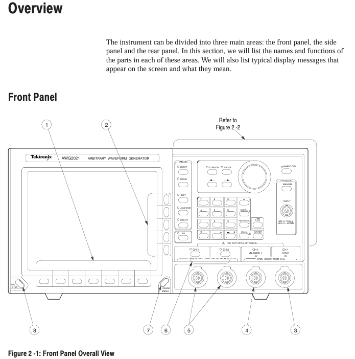
2. Key components of the front-end panel
Specific functional operation examples for component categories
MEAS key in function selection area: switch measurement function; F. G key: Switch to function generator mode and press F. G key to enter standard waveform settings such as sine/triangle/square wave
Menu Control Area MENU Column: SETUP (Parameter Configuration), MODE (Run Mode), EDIT (Editor), LOAD/SAVE (File Management), UTILITY (System Settings) Press the EDIT key to enter the initial menu for file editing
Universal knobs in the data operation area: adjust values/select files; Numerical keys (0-9/.+-): input parameters; Unit key (ns/MHz, etc.): Enter the "1"+"MHz" key to specify the unit and set the clock frequency to 1 MHz
Trigger control area TRIGGER INPUT: external trigger input (maximum ± 10 V ₚ₋ₚ); MANUAL key: Manually triggered. In Triggered mode, press the MANUAL key to trigger waveform output once
Output control area CH1/CH2 ON/OFF keys: switch channel output; SYNC/MARK output interface: Sync/Mark signal output. Press the CH1 ON/OFF button, and the LED will light up to indicate that the CH1 waveform output is turned on
Core functional module: Editor and menu configuration
1. Four core editors (EDIT menu)
(1) Waveform Editor (. WFM file)
Function: Create/edit waveform data, supports 3 display formats:
Graphic display: Visualize waveforms, support point drawing, smoothing (spline/linear interpolation), arithmetic operations (absolute value/integral/derivative).
Timing display: Display timing according to data bits (DATA 11-DATA 0), supporting the setting of - pattern (such as NRZ/NRZI encoding).
Table display: Display each point data in binary/hexadecimal/real form, supporting direct editing of numerical values.
Key operations: Select the editing area (left and right vertical cursor), perform cutting/copying/pasting, or insert other waveform files.
(2) Equation Editor (. QU file)
Function: Generate waveforms through mathematical equations, support 100 line equations, compile and generate WFM file.
Support functions: trigonometric functions (sin/cos), exponents (exp), logarithms (log/ln), random numbers (rnd), differentials (diff), integrals (integ), etc.
Example equation: range (0,1ms) sin (2 * pi * x) (generates a single period sine wave within 0-1ms).
(3) Sequence Editor (. SEQ file)
Function: Combine multiple waveform/sequence files and set the number of repetitions for each file (1-65535 times).
Operation process: Select a file from the directory → Set the number of repetitions → Generate a sequence, support "Show Overview" preview of combined waveforms.
(4) Automatic Step Editor (. AST file)
Function: Program waveforms and output parameters (clock/amplitude/filter) step by step, switch one step per trigger, supporting 100 steps.
- OMRON
- ABB
- General Electric
- EMERSON
- Honeywell
- HIMA
- ALSTOM
- Rolls-Royce
- MOTOROLA
- Rockwell
- Siemens
- Woodward
- YOKOGAWA
- FOXBORO
- KOLLMORGEN
- MOOG
- KB
- YAMAHA
- BENDER
- TEKTRONIX
- Westinghouse
- AMAT
- AB
- XYCOM
- Yaskawa
- B&R
- Schneider
- KONGSBERG
- NI
- WATLOW
- ProSoft
- SEW
- ADVANCED
- Reliance
- TRICONEX
- METSO
- MAN
- Advantest
- STUDER
- DANAHER MOTION
- Bently
- Galil
- EATON
- MOLEX
- DEIF
- B&W
- ZYGO
- Aerotech
- DANFOSS
- Beijer
- Moxa
- Rexroth
- Johnson
- WAGO
- TOSHIBA
- BMCM
- SMC
- HITACHI
- HIRSCHMANN
- Application field
- XP POWER
- CTI
- TRICON
- STOBER
- Thinklogical
- Horner Automation
- Meggitt
- Fanuc
- Baldor
- SHINKAWA
- Other Brands
- UniOP
- KUKA
- Iba
- Beckhoff
- ADLINK
-
 ETEL DSCDL332-131C-000A Servo Control Board
 -
 ETEL DSCDP324-322F-000C Dual Motor Driver
 -
 ETEL EA-P2M-400-10/20A Position Controller
 -
 ETEL DSC2P121 and DSO-HIO33 Servo Amplifier Set
 -
 ETEL EA-P2M-400-15/40A AccurET Drive
 -
 ETEL EA-P2M-300-07/15A Position Controller
 -
 ETEL EA-P2M-048-05/10A-0100-01 Servo Drive
 -
 ETEL EA-S0M-300-40/80A Servo Drive Guide
 -
 ETEL DSB2P131-111E-000H Digital Servo Amplifier
 -
 ETEL DSCDP334-421-000 Servo Drive Guide
 -
ETEL EA-S0M-300-40 80A-0000-00 Motion Control Module
-
 ETEL UltimET Light Motion Controller EU-LGP-0-0-1000-01 Multi-Axis
 -
 ETEL DSO-RAC601-029 Controller Rack
 -
ETEL DSMAX212-121C-000C Board
-
 ETEL DSCDL132-212B-000C Position Controller
 -
 ETEL TMB0291-050-3TDS-E82 Torque Motor
 -
 ETEL DSMAX212-121-000 Board
 -
 ETEL DSB2P131-111E-000H Digital Servo Controller Amplifier Unit
 -
 ETEL DSB 2S 124-211E-000H Digital Servo Amplifier
 -
 ETEL AccurET EA-P2M-300-4/7.5A-0100-01 Modular Position Controller
 -
 Beckwith Electric M-6280A Digital Capacitor Bank Control
 -
 Beckwith M-2355B Adapter Panel with M-2001C-6SL Tapchanger Control
 -
 Beckwith M-0359 Syncrocloser MOD512
 -
Beckwith Electric M-2001C-6ELFA Tap Changer Controller
-
 Beckwith M-3311A 4-Coil Transformer Protection Relay
 -
 Beckwith M-0124 Terminal Board Adapter Plate Guide
 -
 Beckwith Pride M-0296C 3-Phase Programmable Relay
 -
 Beckwith M-0388 Syncrocloser Check Relay Guide
 -
 Beckwith M-0170A AC Current Relay Guide
 -
Beckwith M-3311 Transformer Protection Relay Guide
-
Beckwith Electric M3310 Integrated Transformer Protection Panel
-
 Beckwith M-0145 First Customer Protector
 -
Beckwith M-0170A AC Current Relay
-
 Beckwith PRIDE M-0296C 3 Phase Programmable Relay
 -
 Beckwith Pride M-0296b 3-Phase Programmable Relay
 -
Beckwith M-0245C High Speed Sync-Check Relay Guide
-
 Beckwith M-0115A AC Parallel Balancing Module
 -
Beckwith M-0389 Voltage Verifier Relay
-
Beckwith M-0115A Parallel Balancing Module
-
 Beckwith M-0389 Voltage Verifier
 -
 Beckwith PRIDE M-0420 Multifunction Relay Protection Module 48VDC
 -
 Beckwith Electric M-3430 Generator Protection Relay
 -
 Beckwith Electric M-0067E Tapchanger Control
 -
 Beckwith Electric M-0420 Multifunction Relay
 -
Beckwith Electric M-2001D-6L4S20C0S0X Tap Changer Control
-
 Beckwith Electric M3425A-STD1 Generator Protection Relay
 -
Beckwith Electric M-0245C High Speed Sync-Check Relay
-
Beckwith Electric M-3520 Intertie Protection Relay Guide
-
Beckwith Electric M-2001C-6SL Tap Changer Control
-
Beckwith Electric M-2001C Tap Changer Control Guide
-
Beckwith 35-12-635 Generator Protection Keypad Interface
-
Beckwith Electric P-2216 Generator Protection Main Board
-
 Beckwith Electric M-2293 Tap Changer Control Guide
 -
 Beckwith M-4272-6AB1EH0 Integrated Synchronizing Motor Bus Transfer
 -
Beckwith Electric M-4272 Motor Bus Transfer 60-140V 50/60Hz
-
Beckwith Electric M-2001B TapChanger Control
-
Beckwith Electric M-0193B Synchrocloser Unit
-
Beckwith Electric M-0115A AC Parallel Balancing Module
-
Beckwith Electric M-0169A Current Transformer
-
 Beckwith Electric P-1939 Generator Protection Annunciator Panel
 -
Beckwith Electric M-3311A Transformer Protection Relay Guide
-
Beckwith Electric M-0245B High Speed Sync-Check Relay
-
Beckwith Electric M3420 Generator Protection Relay
-
 Beckwith M-0193B Syncrocloser Unit
 -
 Beckwith Electric M-520 Intertie Protection Relay
 -
 Beckwith Electric M-3425A Generator Protection Relay
 -
Beckwith M-3425 Integrated Generator Protection Relay
-
Beckwith M-0115A Parallel Balancing Module
-
Beckwith Electric M-4272 Integrated Synchronizing Motor Bus Transfer
-
Beckwith Electric M-3420 Generator Protection System
-
Beckwith M-0193 Syncrocloser Unit
-
 Basler Electric DECS-250-CN1SN1N Digital Excitation Control System
 -
 Basler Electric BE1-700 E0N2X1N Digital Protective Relay
 -
 Basler Electric SR4A-2B15B3A Static Voltage Regulator 120VAC 50/60Hz
 -
 Basler Electric 9261402111 PCB Control Board 9346000033
 -
 Basler Electric BE28053-002 Transformer BE28053002
 -
 Basler Electric BE3-25A Auto Synchronizer B1D Sync Module
 -
 Basler Electric BE3-GPR Generator Protective Relay
 -
 Basler Electric SCP-250-G-60 VAR Power Factor Controller 9 1100 00 109
 -
 Basler Electric BE3-32-1S1N1 Reverse Power Relay 277V 5A
 -
 Basler Electric ACA1300-60GM Area Scan Camera 106200-17
 -
 Basler Electric UFOV 260 A Protection Module Specs
 -
 Basler Electric BE03303001 Control Module
 -
Basler Electric BE3-GPR-P1BVSF Generator Protective Relay
-
 Basler Electric BE1-87G Solid State Protective Relay Guide
 -
 BASLER ELECTRIC BE1-60 VOLTAGE BALANCE RELAY T176884
 -
 Basler Electric BE1-32R Protective Relay
 -
 Basler Electric 9022900-103 Transformer 6-7VA 60Hz
 -
 Basler Electric BE1-59-A4E-E1K-B1S3F Overvoltage Relay
 -
 Basler Electric KR2FF-M Voltage Regulator 9 1163 00 103
 -
 Basler Electric UFOV 260 A Protective Module
 -
 Basler Electric PCB Assembly 9059701100 919620
 -
 Basler Electric SR8A2B01A3E Static Voltage Regulator
 -
 Basler Electric SSR125-12 Static Voltage Regulator 9185900102
 -
 Basler Electric SSR 63-12 Static Voltage Regulator 600VAC
 -
 Basler Electric BE1-60 Solid State Protective Relay
 -
 Basler Electric BE3-47N/27-3A4N2 Voltage Relay 9320400101
 -
 Basler Electric BE1-59 Over Voltage Relay
 -
 Basler Electric DECS100-B15 Automatic Voltage Regulator
 -
 Basler Electric PRS250 Veri-Sync Relay 9088800102
 -
Basler Electric BE25927001 Current Transformer 1:34 Amp
-
Basler Electric 9170818100 Generator Differential Relay
-
 Basler Electric BE1-59N Solid State Ground Fault Overvoltage Relay
 -
 Basler Electric 1783 DC Current Transformer Coil 1200:5A
 -
Basler Electric BE1-67 Ground Directional Overcurrent Relay
-
 Basler Electric UFOV-260A Underfrequency Overvoltage Module
 -
 Basler Electric BE10493001 Control Module
 -
Basler Electric SSR125-12 Static Voltage Regulator Guide
-
 Basler Electric BE1810/U-2 Solid State Frequency Relay Guide
 -
 Basler Electric 9105100106 UFOV-250A Protector Guide
 -
 Basler Electric MOC2199 9072300-335 Relay Module Guide
 -
 Basler Electric 9289902106 Circuit Board
 -
Basler Electric BE1-32R Protective Relay A1E E1P BOS1P
-
 Basler Electric RAL6144-16GM GigE Line Scan Camera with Lens
 -
 Basler Electric BE3-49R-5I5A1 Temperature Relay
 -
 Basler Electric BE1-32R Power Relay B3E E1R A0N1F
 -
 Basler Electric SR4A2B06B3A Static Voltage Regulator Features
 -
 Basler Electric 9121000106 Manual Voltage Control MVC Guide
 -
Basler Electric SR32A-2B15B3E Static Voltage Regulator
-
 Basler Electric SR4A2B06B3A Static Voltage Regulator Guide
 -
Basler Electric 801A193F02 Hammond Transformer Module
-
 Basler Electric BE1-24 Volts Per Hertz Relay A1E F1J D1S0F
 -
 Basler Electric AEC63-7 Analog Excitation Controller 220-277V
 -
Basler Electric BE132R Power Relay T245579
-
 Basler Electric MVC 108 Manual Voltage Control 90 37000 102
 -
 Basler Electric 9022900-103 Control Transformer 6-7VA 60Hz
 -
 Basler Electric BE1-79M Plug Adapter 9170111102
 -
 Basler Electric 9 2007 00 100 Current Boost System CBS 305


