
YOKOGAWA CONTROL FUNCTIONS OF CENTUM CS 1000
Core design concept:
Integrate the validated high-quality control functions of the CENTUM CS series to ensure control reliability
Strengthen communication capabilities with various subsystems such as programmable logic controllers (PLCs)
Simplify engineering processes, improve on-site equipment compatibility, and reduce application development and maintenance costs through innovative technologies
YOKOGAWA CONTROL FUNCTIONS OF CENTUM CS 1000
Product Overview
Product positioning: Yokogawa is a distributed control system (DCS) developed for small and medium-sized factories, with the core goal of reducing the total cost of ownership (TCO) for users while balancing high functionality and maintainability
Core design concept:
Integrate the validated high-quality control functions of the CENTUM CS series to ensure control reliability
Strengthen communication capabilities with various subsystems such as programmable logic controllers (PLCs)
Simplify engineering processes, improve on-site equipment compatibility, and reduce application development and maintenance costs through innovative technologies
Core functional configuration
(1) Control Function Architecture
Function category, specific content, and function
The minimum control algorithm unit of the basic control component function block (PID controller, selector, etc.) is used to assemble basic control applications
Expand control functions to adjust control blocks, sequence control blocks, SFC blocks, calculation blocks, panel blocks, cover adjustment control, sequence control, batch control and other diverse requirements
Auxiliary management function unit monitoring function is grouped according to process units to manage function blocks, simplifying control and monitoring operations
Input/output function process, I/O implementation, and signal input/output of general sensors and actuators
Input/output function communication I/O achieves signal transmission through universal communication interfaces such as RS-232C
Status prompt function sequence message, alarm real-time feedback system operation status and abnormal information
(2) Reliability Design
Adopting a synchronous hot standby system and continuing the on-site validated FCS reliability design of the CENTUM CS series
Core advantage: In case of sudden CPU failure during operation, the control can seamlessly switch to the backup CPU without interrupting the control action, especially suitable for batch production processes guided by sequence control
Engineering Efficiency Optimization: FCS Template
(1) Design background
The control application is composed of multiple functional blocks, which occupy different internal resources and CPU loads
FCS memory is limited, and if functional blocks are combined in an unordered manner, professional personnel need to estimate resources and load, which is difficult
(2) Template advantages and classification
Core value: Preset database templates according to user expectations for application scenarios, automatically allocate FCS database resources reasonably, and strictly control CPU load to not exceed the limit
Template types: covering three typical application scenarios of regulation control, sequence control, and monitoring, users can directly choose, greatly simplifying the engineering design process
On site communication flexibility design
(1) Core pain point resolution
To address the issues of dispersed on-site control equipment and diverse data types and communication interfaces, two measures are taken to achieve flexible adaptation:
Specific measures to achieve advantages
Separation of Communication Function and Control Application: 1. Data obtained through communication is stored in the "Communication I/O Area"
2. Control the application to access the area through relative addresses or custom tags
3. The system automatically recognizes data types (integers, floating points, etc.) without the need to modify control applications due to communication protocol changes, reducing engineering complexity
C programming adaptation protocol 1. Develop ready-made communication packages for commonly used protocols
2. Special protocols can be encoded in C language to achieve compatibility with multiple universal communication interfaces and protocols, and adapt to different field devices
Innovative virtual testing function: simulator system
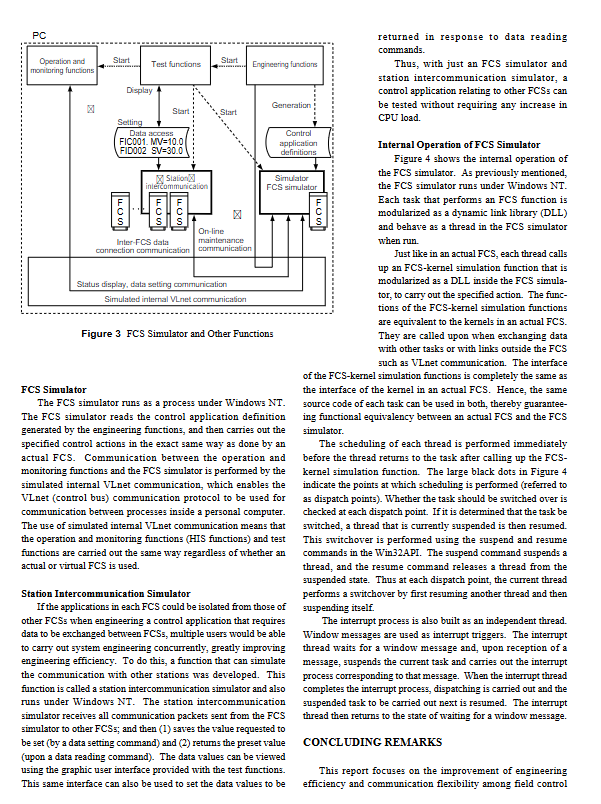
(1) FCS simulator
Operating environment: Windows NT operating system
Core function: Read the control application definitions generated by engineering functions, fully simulate the control actions of actual FCS
Communication mechanism: By simulating internal VLnet communication to achieve interaction with operation monitoring and testing functions, the operation logic is consistent with the actual FCS
Core value: Testing and inspection of control applications can be completed without the need for actual FCS hardware, reducing the cost of building engineering environments
(2) Inter station communication simulator
Design objective: To support control application testing for data exchange between multiple FCS
Working Principle:
Receive all communication data packets sent by the FCS simulator to other FCS
Save the request value of the data setting command and return the preset value when responding to the data reading command
Support viewing and setting return data through a graphical interface
Advantages: Multiple users can carry out system engineering in parallel, improving efficiency without increasing CPU load
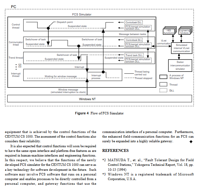
(3) Internal operating mechanism of FCS simulator
Modular design: Each FCS functional task is encapsulated as a dynamic link library (DLL) and runs as a thread at runtime
Kernel adaptation: The FCS kernel simulation function is completely consistent with the actual FCS kernel interface, ensuring source code reuse and functional equivalence
Scheduling mechanism: After a thread calls the kernel simulation function, it triggers scheduling (scheduling point) and switches threads through the suspend/resume command of the Win32 API
Interrupt handling: An independent interrupt thread, triggered by a window message, pauses the current task when interrupted, and resumes scheduling after processing is completed
Summary and Future Prospects
Core achievement: Through FCS templates, flexible communication design, and virtual testing capabilities, we have achieved a unified improvement in engineering efficiency, enhanced adaptability of on-site equipment, and high reliability
Future direction: Plan to further expand open interfaces and cross platform features, extend FCS simulator technology to scenarios such as PC direct control processes and gateway function development, and strengthen the gateway application potential of on-site communication functions
Key issues
Question 1: Through which designs does the CENTUM CS 1000 reduce total cost of ownership (TCO)? Please explain from three dimensions: engineering, hardware, and maintenance.
Answer: 1 Engineering dimension: Provide FCS templates (regulation control, sequence control, monitoring), automatically allocate resources, control CPU load, simplify design process; Innovative FCS simulators and inter station communication simulators can complete application testing without actual hardware, reducing the cost of building engineering environments. 2. Hardware dimension: Integrating mature control functions and enhanced communication capabilities of the CENTUM CS series, without the need for additional dedicated communication modules, reducing hardware procurement costs. 3. Maintenance dimension: The communication function is separated from the control application, and there is no need to modify the control application when the protocol is changed; The synchronous hot standby system ensures uninterrupted control in case of CPU failure, reduces downtime maintenance losses, and overall improves system maintainability.
Question 2: How does CENTUM CS 1000 solve the problem of diversified communication of on-site control equipment? What are the advantages of its communication architecture?
Answer: Solution: 1 Adopting a "communication function and control application separation" architecture, communication data is stored in a separate "communication I/O area", and control applications access it through addresses or tags to automatically identify data types. Protocol changes do not affect control applications; 2. Provide commonly used protocol communication packages, special protocols support C language encoding adaptation, and are compatible with multiple interfaces and protocols. Advantages of Communication Architecture: 1 Strong flexibility, adaptable to dispersed and diverse on-site control equipment; 2. High stability, separate design reduces the impact of single module failure on the overall system; 3. Good scalability, supporting quick adaptation when adding or replacing on-site devices in the later stage.
Question 3: How do the FCS simulator and inter station communication simulator of CENTUM CS 1000 work together to achieve full process coverage of virtual testing?
Answer: Collaborative process: 1 Preliminary preparation: Generate control application definitions through engineering functions and import them into the FCS simulator; 2. Single FCS testing: The FCS simulator runs on the Windows NT system, simulating actual FCS control actions, and verifying the control logic of a single FCS by simulating internal VLnet communication and operation monitoring functions, as well as testing function interactions; 3. Multi FCS interaction test: Enable inter station communication simulator, receive cross FCS communication data packets sent by the target FCS simulator, save setting requests or return preset data, simulate data interaction between multiple FCS; 4. Result verification: View data status and set return values through a graphical interface to complete the full scenario testing of the control application. Core value: It can cover the entire process of testing from single FCS to multi FCS collaboration without the need for actual FCS hardware and multiple device networking, greatly improving engineering efficiency and reducing testing costs.
- OMRON
- ABB
- General Electric
- EMERSON
- Honeywell
- HIMA
- ALSTOM
- Rolls-Royce
- MOTOROLA
- Rockwell
- Siemens
- Woodward
- YOKOGAWA
- FOXBORO
- KOLLMORGEN
- MOOG
- KB
- YAMAHA
- BENDER
- TEKTRONIX
- Westinghouse
- AMAT
- AB
- XYCOM
- Yaskawa
- B&R
- Schneider
- KONGSBERG
- NI
- WATLOW
- ProSoft
- SEW
- ADVANCED
- Reliance
- TRICONEX
- METSO
- MAN
- Advantest
- STUDER
- DANAHER MOTION
- Bently
- Galil
- EATON
- MOLEX
- DEIF
- B&W
- ZYGO
- Aerotech
- DANFOSS
- Beijer
- Moxa
- Rexroth
- Johnson
- WAGO
- TOSHIBA
- BMCM
- SMC
- HITACHI
- HIRSCHMANN
- Application field
- XP POWER
- CTI
- TRICON
- STOBER
- Thinklogical
- Horner Automation
- Meggitt
- Fanuc
- Baldor
- SHINKAWA
- Other Brands
- UniOP
- KUKA
- Iba
- Beckhoff
-
 Mitsubishi MELSEC A2ASCPU PLC System
 -
 PC PMC25.2-002 PLC Module
 -
 B&R X20CP1382 Programmable Controller
 -
 Siemens C98043-A7002-L4 PC Board
 -
 Fanuc A16B-3300-0057 PCB Board
 -
 Schneider LV430403 Circuit Breaker TM160D
 -
 ABB CI810B 3BSE020520R1 PLC Interface
 -
 Omron R88D-HT10 Servo Drive
 -
 Omron CS1G-CPU43H CPU Unit
 -
 Mitsubishi QD70D4 Positioning Module
 -
 Siemens 6FC5110-0BB04-0AA1 Sinumerik 840C CPU
 -
 Siemens 3RT5045-1AC20 SIRIUS Contactor 75kW
 -
 Siemens 3VA2340-5HL32-0AA0 Circuit Breaker 400A
 -
 ABB HBS01-CJC I/O MTUS SD Series Module
 -
 Eberle MT42 Complete PLC Rack PLS514
 -
 Siemens C8451-A201-A9 PLC Card Slot Backplane
 -
 Cherokee ACX643 REV-B Power Supply Unit 100-240VAC
 -
 Schneider SSD1A320BDC1 Solid State Relay 20A
 -
 GE Fanuc IC694APU300 High Speed Counter Module
 -
 Schneider 140DA175300 Analog Output Module
 -
 Allen Bradley 1794-OA8I FLEX 8-Point Digital Output Module
 -
 Phoenix Contact PLC-BPT-24DC/1/SEN Solid State Relay Module
 -
 Schneider IG2000PG2 PLC Module Industrial Controller Card
 -
 Mitsubishi LE-40MTA-E Tension Controller Web Handling Control
 -
 Siemens 6FX1122-1AC02 PLC Card Industrial Interface Module
 -
 ABB AF210-30-11 Contactor Coil Voltage 110-240VAC
 -
 Mitsubishi GT2508-VTBD GT2508-VTBA HMI Touch Screen Panel
 -
 BPT 67200020 Touch Screen PLC Display Multifunction Terminal 50Hz
 -
 NORIS A1-91 PCB Rack Module A1-91-4 A1-91-5 A1-91-6 A1-91-7
 -
 Mitsubishi A1S61PN Power Supply Unit AnS Series 5VDC 5A
 -
 Pilz 312070AA PSSU H PLC1 FS SN SD Safety Module
 -
 Pasaban MTC-3044 PLC Rack with Power Supply Card
 -
 Schneider METSEPM8243 Power Meter PM800
 -
 Fanuc A16B-1212-0100-01 Power Supply Unit
 -
 Honeywell DPCB21010002 PCB IRTP-161 REV A
 -
 Siemens 6ES7315-2AH14-0AB0 CPU 315-2 DP
 -
 Omron GRT1-DA2V Analog Output Module 2 Channels
 -
 Mitsubishi FX3U-128MT/ESS PLC CPU Module
 -
 Schneider SSP05EMA12 Soft Starter Altistart 22
 -
 Mushroom 787602 Push Button Head 40mm
 -
 Hydraulik Elektronik EPM8900 91221 Proportional Module
 -
 ABB XZ C828 A101 Didt Dioder Snubber 3BHE039453R0101
 -
 ABB 3BHE032593R0001 Isolated Power Supply
 -
 ABB 3BHB02722R0001 single-phase charging transformer
 -
 ABB 3BHE006412R0101 UFC762AE101 main control board
 -
 ABB XVC770BE101 3BHE021083R0101 interface board
 -
 ABB 3BHE024747R0101 GD C801 Overvoltage Protection Motherboard
 -
 ABB 3BHE021887R0101 3BHB002751R0102 Variable Frequency Control Board
 -
 ABB SD812 power module 3BSC610023R0001
 -
 Automotive LC4A00010 Brushless Motor Controller
 -
 Doric NC500 Neuroscience Data Acquisition System
 -
 Honeywell X-DCS2000/EN Broadcast Manager
 -
 Kollmorgen S60600 servo drive 6A 480V
 -
 Honeywell 30751044-008 ROM Card
 -
 Honeywell 5SE1-12 Micro Switch Specifications
 -
 Schneider AS-BDAU-204 Analog Output Module
 -
 K93712 Expansion Kit Industrial Module
 -
 MGE DCHEN 3400116300 Circuit Board
 -
 Siemens 6SE7036-1EE85-1HA0 Rectifier Board
 -
 Renesas UPD70F3624GBA1 Microcontroller
 -
 Omron E5AC-CX4A5M-014 Temperature Controller Parameters
 -
 GE IS200TBCIH1BCE Contact Input Board
 -
 Fanuc A05B-2255-C101#EAW Teach Pendant Data
 -
Rieter RMC186C RMC RIO-1 PLC Controller
-
 Siemens PXC24.2-EF32.A Building Automation Controller
 -
 Fanuc A16B-1200-0220 PC Memory Board F3
 -
 Omron CJ2M-CPU33 PLC CPU Module
 -
 Beckhoff EL1918 Safety Input Terminal EtherCAT
 -
 Fanuc A16B-1212-0871 CNC PCB Board
 -
 GE Fanuc IC697BEM713J PLC Module
 -
 Mitsubishi A2ACPU-R21 PLC CPU Module
 -
 Programmable Relay 230V AC 16 Inputs 8 Outputs T2UK
 -
 Schneider F3SP71-4S Safety PLC Module
 -
 NEED-24DC- T2UK Programmable Relay 24V 16in 8out
 -
 Siemens 3RT1075-6SP36 SIRIUS Power Contactor 200kW
 -
 GE 1C31170G02 Printed Circuit Board Module 94V-0
 -
 BPT 67200020 Multifunction Touch Terminal 50Hz
 -
 Fanuc A16B-2200-0931 Option Board with Daughter Cards
 -
 Honeywell FC-SDOL-0424 I/O Module Board
 -
 Lenze EMF2179IB DeviceNet Communication Module
 -
 Yaskawa CIMR-JC4A0007BAA J1000 VFD 0.4kW
 -
 Yokogawa PSBCMNBN Bus Continuation Module ProSafe-PLC
 -
 Phoenix Contact PLC-BPT-24DC/1/SEN Solid-State Relay
 -
 Allen-Bradley 193-EC2AB E3 Plus Overload Relay
 -
 GE DS200TCTGG1AFF Turbine Control Board
 -
 Westinghouse 1C31170G02 Ovation Module
 -
 Mitsubishi A2ACPU21 Programmable Controller Review
 -
 710-95045-AD PLC I/O Operation Console Cable
 -
 Allen-Bradley 1785-L11B PLC-5 Processor Specifications
 -
 BEMAC UST-202-D 1307D V08B2 Circuit Board
 -
 Pilz 312070 PSSu H PLC1 FS Safety Module
 -
 Keyence QS-MB1 Safety Network Module Overview
 -
GE Fanuc IC693CPU372 CPU Module 90-30 Series
-
 Mitsubishi RJ71EIP91 EtherNet/IP Module
 -
 Schneider LXM62DD27D21000 Lexium 62 Servo Drive
 -
 Mitsubishi Q13UDEHCPU Universal PLC CPU Module
 -
 B&R X20CP3585 Programmable Controller X20 CPU
 -
 Siemens 6FC5203-0AF02-0AA0 Sinumerik Operator Panel
 -
 IWKA PG02 VKR TEL-Z Self-Sufficient Measuring System
 -
 Schneider BMXCPS2010 PLC Power Supply Modicon M340
 -
 Mitsubishi A171SCPU Motion Servo CPU Specifications
 -
 PLC Board with Finder 44.52 Relay Module 6A 250V
 -
 Honeywell DOP 09436601 Measurex Module Data
 -
 Fanuc A20B-8101-0320 CNC Circuit Board
 -
 KUAX 680I V.24 PLC Module 68142304
 -
 Allen Bradley 1785-L30B PLC 5/30 Processor
 -
 Phoenix ILC 191 ETH 2TX 2700976 Ethernet Controller
 -
 Siemens 6SY7000-0AC80 PLC Power Supply Module
 -
 Reliance Electric MACS 804.46.20 CWW PLC Drive
 -
 Omron CP1E-N60DR-D PLC CPU 36 Input 24 Output
 -
 Mitsubishi Melsec PLC System A2ACPU A63P AY13E AX82
 -
 Square D PAF361600DC1680 2000A Circuit Breaker
 -
 MERLIN GERIN STR 58U 5000A Electronic Trip Unit
 -
 Omron CJ1W-SCU21-V1 Serial Communication Unit
 -
 SICK S30A-6011EA S3000 Safety Laser Scanner
 -
 Mitsubishi Q00JCPU-S8 Universal Programmable Controller
 -
 Allen-Bradley 20AB9P6C3AYNANC0 PowerFlex 70 AC Drive
 -
 SYSMELEC Handheld Robot Automation Controller
 -
 LG Display LB315WRM-SVA1 32 Inch 4K LCD Panel
 -
 Mitsubishi Kakoki E Series PLC I/O Modules
 -
 Allen-Bradley 1440-VST02-01RA Dynamic Measurement Module
 -
 Beckhoff EL5042 EtherCAT Encoder Terminal
 -
 Beckhoff CX5010-0112 Embedded PC Controller
 -
 Guardmaster 440R-D22R2 Safety Relay Specifications
 -
 NL12880BC20-10ND Industrial Display Panel Data
 -
 LFI 12X5326-S1 Slide-in Control Board Technical Data
 -
 Modicon AS-9370-001 Programmable Controller Data
 -
 Mitsubishi Kakoki E-01B-4130 PLC Module Overview


