
YOKOGAWA CENTUM CS 3000 Integrated Production Control System
YOKOGAWA CENTUM CS 3000 Integrated Production Control System
System Overview
CENTUM CS 3000 is an integrated production control system for medium and large process control applications. This system is a synthesis of the latest technology with Yokogawa’s experience and specialist know-how. This new system has the functionality, flexibility and reliability of our CENTUM CS, and is also based on the V net control bus.
1.1 Yokogawa’s Enterprise Technology Solutions Concept
Enterprise Technology Solutions
• Enterprise:Enterprise viewpoint
• Technology:Latest technology
• Solutions:Optimum solutions
Yokogawa’s “Enterprise Technology Solutions” provide management with systems that integrate control of both factory and business, allowing management to improve profits. We use the latest technology, and can provide optimum solutions which satisfy customer requirements. Yokogawa can provide complete solutions: sophisticated information and control systems, plant-simulation production support systems, the latest field instrumentation – complete packages of the latest equipment and software technology, plus a complete range of services: from plant design, installation and startup through maintenance.
1.2 System Concepts
CENTUM CS 3000 is Yokogawa’s flagship control-system platform for launching Enterprise Technology Solutions. Its open interfaces facilitate data access from supervisory systems such as Enterprise Resource Planning (ERP) Systems and Manufacturing Execution Systems (MES), and make it easy to create a strategic management information system f
or your enterprise. CENTUM CS 3000 is a scalable, compatible system-designed to work with your existing systems, and grow with your business, reducing total cost of ownership (TCO).
1.3 Solutions Incorporating CENTUM CS 3000
CENTUM CS 3000 is a key part of most of Yokogawa’s Enterprise Technology Solutions, and features:
• Open environment for optimizing the whole enterprise,
• Optimal operating environment, hardware upgradeable to the latest technology,
• Flexible, durable system that can be optimized for your plant,
• Minimize total cost of ownership, increase profits,
• Powerful engineering functions,
• Improved Security and Safety for Plants.
2. System Configuration
2.1 System Configuration – CENTUM CS 3000 Equipment
Human Interface Station (HIS)
The HIS is mainly used for operation and monitoring – it displays process variables, control parameters, and alarms necessary for users to quickly grasp the operating status of the plant. It also incorporates open interfaces so that supervisory computers can access trend data, messages, and process data.
• Console Type HIS
This is a new console type human interface station, at which a general purpose PC is installed.
There are two types of console type HISs: one is enclosed display style, the appearance of which is usual style, and another is open display style, the configuration of which is selectable.
• Desktop Type HIS
This HIS uses a general purpose PC.
Field Control Station (FCS)
The FCS controls the plant. By the difference of used I/O modules, there are two models of the FCS; namely the FCS for FIO and the FCS for RIO. In addition to the above models, there is the Compact type FCS.
• FCS for FIO
This FCS uses the Fieldnetwork I/O (FIO) modules, which are compact and consist of various lineup such as the connector types and so forth. According to the application capacity, there are the standard model and the enhanced model.
• Compact FCS for FIO
This is a compact FCS with I/O modules integrated into the Field Control Unit.
• FCS for RIO
This FCS uses the Remote I/O (RIO) modules, which have many installation bases and M4 screw terminals to connect signal cables. According to the application capacity, there are the standard model and the enhanced model.
• Compact FCS for RIO
This controller is usually installed near the equipment or process it controls, and is ideal for communicating with subsystems.
Engineering PC (ENG)
This is the PC with engineering functions used to perform CENTUM CS 3000 system generation and maintenance management.
It can be the same type of general-purpose PC as the HIS, and can even be the same PC as the HIS.
By having HIS operation and monitoring functions on the same PC, you can use the test (control station emulation) functions to provide an efficient and easy-to-use engineering environment.
Bus Converter (BCV)
This links the V net system bus to another CENTUM CS 3000 domain or to an existing CENTUM or µXL system.
Communications Gateway Unit (CGW)
This links the V net control system bus to an Ethernet bus (to a supervisory computer system or general purpose personal computer).
By CGW wide area communication function, you can also link two CENTUM CS 3000 V nets in different places using a dedicated telephone line.
Migrated Field Control Station (RFCS2)
You can leave the I/O cards and field wiring of a CENTUM-XL or CENTUM V system “as is”, and replace the CPU nest with an KFCS, which can be connected to the V net just like a CENTUM CS 3000 system FCS.
SI bus is used as a (dual-redundant) bus connecting existing FCS I/O units to new FCS CPU.
Advanced Process Control Station (APCS)
The Advanced Process Control Station (APCS) is a personal computer (PC) connected to the V net and applied to advanced process control and efficiency improvement.
Generic Subsystem Gateway Package (GSGW)
GSGW is a PC connected to V net. It uses OPC servers for subsystems, facilitating subsystem data acquisition and setting without creating specific communications programs.
Exaopc
This provides OPC Server functions to enable applications in a supervisory PC to access CENTUM CS 3000 data. It provides a link between control layer and business data processing layer.
Business Information PCs and Supervisory Computers
These can run MES and ERP integrated business management software. They can access the DCS via Exaopc or CGW.
Safety Instrumented System (ProSafe-RS)
ProSafe-RS is a dedicated system to prevent probability and spread of accidents when it is used as an interlock device, emergency shutdown system and fire and gas protection.
Safety Engineering PC (SENG)
This is a component equipped with engineering, test and maintenance functions to generate system and manage maintenance for safety control station (SCS).
Safety Control Station (SCS)
This is a safety controller that executes logics for systems including interlock, emergency shutdown and fire and gas protection.
V net
The V net real-time control system bus links stations such as FCS, HIS, BCV and CGW. Dual-redundant V net support is standard.
Ethernet
Ethernet is used to link HIS, ENG and supervisory systems. It is also used for transferring data files to supervisory computers, and for HIS data equalization.
Fieldbus
The FOUNDATION Fieldbus is a multidrop digital communications bus for field instruments, and is expected to replace the conventional 4 to 20 mA analog interface.
2.2 System Specifications
CENTUM CS 3000 is a flexible system that can handle everything from small to quite large systems.
System Scale
The CENTUM CS 3000 system specifications are as shown below:
• No. of tags that can be monitored: 100,000 tags (expansible up to 1,000,000 tags)
• No. of stations that can be connected: 256 stations (max. 16 domains, 64 stations per domain) – however, HIS is limited to a maximum of 16 stations/domain.
Domain
A domain is a logical V net bus segment. You can use a Bus Converter to link CENTUM CS 3000 domains, or link to previous systems (CENTUM CS, CENTUM-XL, CENTUM CS 1000, µXL etc.). Support will be provided for integrating CS 3000 with previous systems.
Migration from CENTUM CS 1000 to CS 3000
Easy engineering operation can migrate the existing CENTUM CS 1000 system to the CENTUM CS 3000 system.
Single control bus is available when the CENTUM CS 3000 Entry class system is migrated from the CENTUM CS 1000 system. In that case, Ethernet is not required.
2.3 Human Interface Station (HIS)
2.3.1 Console Type HIS
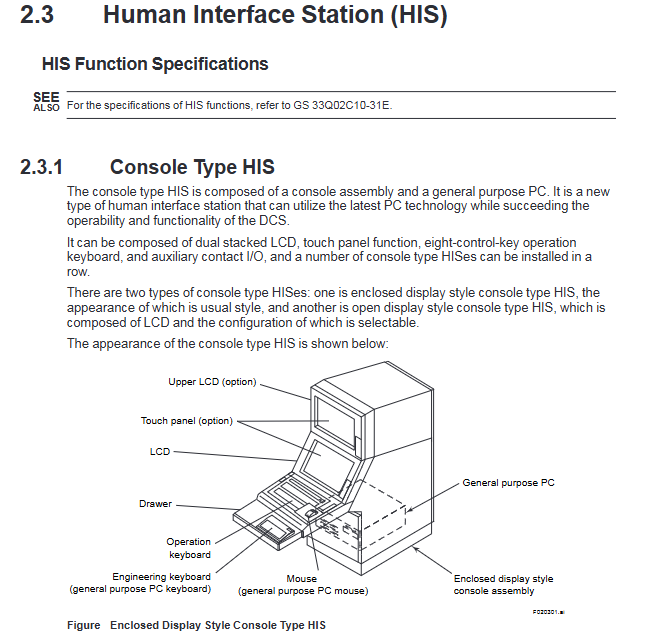
The console type HIS is composed of a console assembly and a general purpose PC. It is a new type of human interface station that can utilize the latest PC technology while succeeding the operability and functionality of the DCS.
It can be composed of dual stacked LCD, touch panel function, eight-control-key operation keyboard, and auxiliary contact I/O, and a number of console type HISes can be installed in a row.
There are two types of console type HISes: one is enclosed display style console type HIS, the appearance of which is usual style, and another is open display style console type HIS, which is composed of LCD and the configuration of which is selectable.
2.3.2 Desktop Type HIS
The Desktop Type HIS uses a general purpose IBM PC/AT compatible.
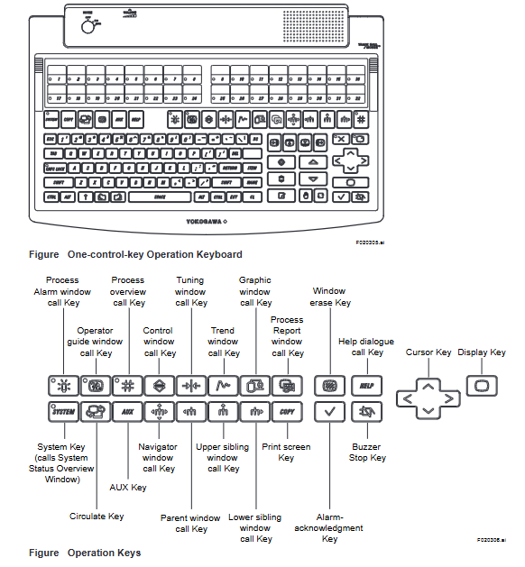
2.3.3 Operation Keyboard
The dust- and drip-proof operation keyboard has functionally arranged flat keys, which enables one-touch operation. The keyboard is available in two types: one is designed for eight-control-key operation for use with console type HISes, and another for one-control-key operation for use with both console type HISes and desktop type HISes.
2.4 Field Control Station (FCS)
The hardware architecture of the Standard Type Field Control Station for FIO (KFCS), the Enhanced Type Field Control Station for FIO (KFCS2), the Standard Type Field Control Station for RIO (LFCS), the Enhanced Type Field Control Station for RIO (LFCS2), and the Compact FCS (SFCS) is described below.
KFCS, KFCS2:The Field Control Unit (FCU) and the node are connected using ESB(Extended Serial Backboard) or ER(Enhanced Remote) bus.
FFCS:An FCS in which the FCU and a node unit are combined.
LFCS, LFCS2:The FCU and the node are connected using RIO bus.
PFC-H/-S/-E:The FCU and the I/O units are connected to the same backplate.
2.5 I/O Module Nests and I/O Modules
This section describes input modules, which convert process signals to digital data format used in the FCS, and output modules, which convert the digital data to analog or contact signals.
For I/O modules, there are the Fieldnetwork I/O (FIO), which are compact and consist of various lineup, and the Remote I/O (RIO), which have many installation bases.
2.5.1 Fieldnetwork I/O (FIO)
The FIO modules are used in the FCS for FIO. They are compact and consist of the lineup of abundant variety, such as the connector types, the isolation types, and so forth, to correspond flexibly to the applications.
Field Wiring Using Pressure Clamp Terminals
A field signal cable, with its end uncovered, can be connected directly to an analog or digital I/O module equipped with the pressure clamp terminal block. Two to three signal cables can be connected for every I/O channel.
Field Wiring Using KS Cable Interface Adapter
An analog or digital I/O module equipped with the KS cable interface adapter can be connected with the terminal board using the KS cable and field signal cables are connected to the terminal board with M4 screws.
2.5.2 Remote I/O (RIO)
The RIO modules are used in the FCS for RIO and Compact FCS. They are field-proven by the many installation bases, and designed basically by the isolated channels and M4 screw connections. The RIO modules are installed in the I/O module nests.
I/O Module Nests
I/O Modules Nests are available in the following types:
• AMN11: Nest for Analog I/O Modules
• AMN12: High-Speed Nest for Analog I/O Modules (for LFCS only)
• AMN21: Nest for Relay I/O Modules
• AMN31: Nest for Terminal-type I/O Modules
• AMN32: Nest for Connector-type I/O Modules
• AMN33: Nest for Communication Modules
• AMN34: Nest for Multipoint Control Analog I/O Modules
• AMN51: Nest for Communication Cards and Ethernet Communication Modules (for Compact FCS only)
• AMN52: Nest for Profibus Communication Module (in Compact FCS only)
I/O Modules
Input modules convert process signals to the digital data format used in the FCS. Output modules convert the digital data format used in the FCS to analog or contact signals. A list of I/O Modules is shown below:
Analog I/O Module
An analog I/O module is installed in Model AMN11, Nest for Analog I/O modules. Up to 16 I/O modules are installed in one nest. Signal cables are connected by M4 screws to the terminals of analog I/O module nest. For each I/O channel, two signal cables or three (for RTD) are connected.
Terminal Type Digital I/O Module
Up to two terminal type digital I/O modules can be installed in one Model AMN31 Nest for Terminal-type I/O Modules. Signal cables are connected by M4 screws to the terminals of modules. For each I/O channel, one or two signal cables are connected.
Connector Type Digital I/O Module
The Connector Type Digital I/O Module is installed in the Nest for Connector-type I/O Modules (AMN32). Up to four modules are installable in one nest. To connect to the MUB/MUD Terminal Board or TE16/TE32 Terminal Block, a KS2 cable is used for ADM11C and ADM51C 16-point modules and a KS9 cable for ADM12C and ADM52C 32-point modules.
Signal cables from field devices are connected by M4 screws to the terminal board or terminal block.
One or two signal cables are connected to each I/O channel.
Multipoint Control Analog I/O Module
AMC80 Multipoint Control Analog I/O Module is installed in the Nest for Multipoint Control Analog I/O Modules (AMN34). Up to two modules are installable in one nest. One module can process 8 inputs and outputs for control. Two modules installed in one nest may separately process different inputs and outputs or be dual-redundant. A KS1 cable connects the module to the MHM Signal Conditioner Nest. Compared with analog I/O modules, cost per point is less these for multipoint modules.
Terminal Type Multiplexer Module
The terminal type multiplexer module is installed in the Nest for Terminal-type I/O Modules (AMN31). Up to two modules can be installed in one nest. Signal cables are connected by M4 screws to the terminals of the module. Two or three signal cables are connected for each I/O channel.
Connector Type Multiplexer Module
The connector type multiplexer module is installed in the Nest for Connector-type I/O Modules (AMN32). Up to four modules can be installed in one nest. Using a KS2 cable (or a KU2 cable), connect it to Signal Conditioner Nest, MUB/MUD Terminal Board or TE16/TE32 Terminal Block.
Connect signal wiring from the field to the terminals of the terminal board or the terminal block with M4 screws.
Relay I/O Module
The relay I/O module is installed in the Nest for Relay I/O Modules (AMN21). Only one module is installable in one nest. Signal cables are connected to the terminals of the module with M4 screws. Two or three signal cables are connected for each I/O channel.
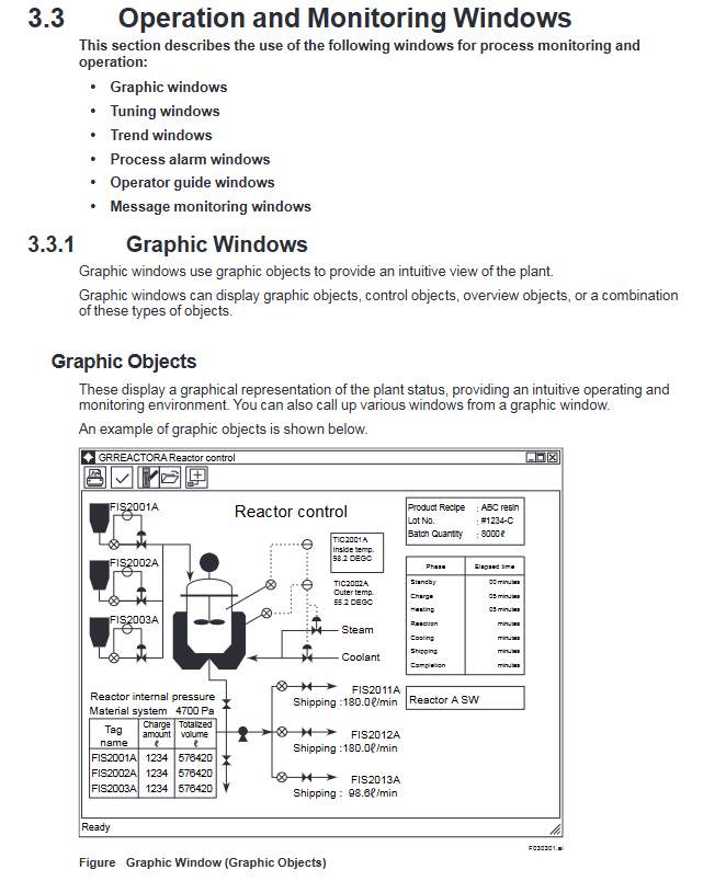
3. Operation and Monitoring Functions
Windows-Based Open Interface
The HIS software runs on a Windows based general purpose PC. Not only CENTUM CS 3000 HIS software but also general Windows application software (such as Microsoft Excel) can be run on the machine. In addition, open software interface OPC (OLE for Process Control) is supported. You can use the operator station not just for operating, but can also run office applications on it to write reports and memos, and to analyze process data.
Support for Latest PC Hardware
Personal computer (PC) technology is progressing very quickly. CPU and network speeds are increasing, CPU and memory prices are falling. Since a general purpose PC (IBM PC/AT Compatible) is used, you can incorporate the latest hardware in your system.
Enclosed Display Style Console Type HIS
The Enclosed Display Style Console Type HIS is composed of a console assembly and a general purpose PC. It is a new type of human interface station.
It can be composed of dual stacked LCD, touch panel function, eight-control-key operation keyboard, and auxiliary contact I/O while succeeding the operability of the existing humanmachine interface.
Open Display Style Console Type HIS
The Open Display Style Console Type HIS is composed of a console assembly and a general purpose PC. It is a new type of human interface station.
It is composed of LCD. As the options, dual stacked LCD, touch panel function, eight-controlkey operation keyboard, and auxiliary contact I/O can be selected, so that its configuration is selectable.
One-touch Multi-window Display Functions
Multiple windows (related windows) can be displayed simultaneously; dynamic window set functions allow you to register a group of windows and display them with the touch of a key.
High-speed Data Update
Data acquisition functions allow display updating as fast as 1 sec. This level of performance is required for manual control of pressure and flow.
Multi-monitor Function
The multi-monitor function enables one general purpose PC to use two monitors, permitting to display more information.
4.1 Configuration of FCS Control Functions
4.1.1 Function Blocks
Function blocks are the basic unit for performing control and calculations. Continuous control, sequence control (sequence tables and logic charts) and calculations are performed by function blocks. Continuous control blocks, calculation blocks, and sequence control blocks are interconnected in a manner similar to the conventional instrument flow diagrams.
4.1.2 Control Drawings (Option)
A control drawing consists of two or more control blocks representing a control function, and makes it easy to perform engineering and maintenance. The control drawing makes it easy to monitor process phases, and the status of related groups of devices, rather than monitoring on an individual-device basis.
Refer to Item 3.6.1 for an example of a control drawing display.
The features of control drawings are described below.
You can mix Continuous and Sequence Control
You can mix continuous and sequence control in a control drawing, and create control functions which match your process.
Free Signal Flow between Control Drawings
Function block I/O signals may extend outside a control drawing to another control drawing. Functionally this is the same as signals between function blocks on a single control drawing.
4.1.3 Regulatory Control Functions
These functions support continuous-process feedback control. Function blocks which support continuous processes are provided.
Regulatory Control Blocks
These control blocks are for controlling analog (continuous) process variables.
Some representative regulatory control function blocks are shown below. The labelled boxes on the outside of the function block represent I/O terminals. Symbols in circles, and lists of items in brackets, represent data items.
For regulatory control blocks, process variable inputs, cascade set points, manipulated variable outputs – such inputs and outputs to / from the block are expressed as 0 to 100%, as illustrated in the figure below. (Thermocouple and RTD temperature data are in temperature units.)
4.1.4 Sequence Control Functions
Sequence control performs several control steps in a predefined sequence.
Types of Sequence Control
• Program control (multi-phase type):Performs control according to a predefined program.
• Conditional control (supervisory type):Monitors the process status and performs conditional control.
Methods of Representing Sequences
You can create a sequence control program to run in the FCS using sequence tables, Sequence Flow Charts (SFC), and logic charts. The relationship between sequence control blocks and other function blocks, process I/O and software I/O is illustrated below.
The figure below shows how sequence control blocks (which contain the sequence control functions) relate to other function blocks, process I/O, and software I/O.
Sequence Table Block
Sequence table blocks are decision-table-format function blocks with input signal logic and output signal logic represented by Y/N patterns. They can connect to other function blocks, and are ideal for creating monitoring sequences or phase progress sequences.
Refer to item 3.6.2 for an example of a sequence table block display.
An example of a sequence table block is shown below.
Logic Chart Blocks
A logic chart consists of function blocks of interlock block diagram type, which describe the relationship between input signals (condition signals) and output signals (action signals) with logic-operation elements. The main function is to control interlock sequences.
Switch Instrument Blocks
Switch instrument function blocks are used for monitoring, for starting and stopping motors and valve actuators, and opening/shutting ON/OFF valves. In general, they are used with sequence table blocks or logic chart blocks.
Sequence Element Blocks
Sequence Element Blocks include timers, counters and code conversion blocks, and are mainly used for sequence I/O signal processing.
Valve Monitoring Blocks
Valve monitoring blocks are used for monitoring the ON/OFF status of valves and for comparing the manipulated output signal with the answerback signal from the valve.
SFC Block Functions
SFC Block Functions execute application programs expressed as Sequential Function Charts (SFCs). SFC Blocks are used for large-scale sequence control and device control. Phase progress management (status display) is easy. When an SFC program is created, each program step represents a group of actions. Each step of the SFC may be a sequence table or a SEBOL program (see Figure).
Refer to ltem 3.6.5 for an example of a SFC block display.
SEBOL Functions
SEBOL (SEquence and Batch Oriented Language) is used to write application programs. The I/O from other function blocks (continuous control blocks, sequence control blocks, and calculation blocks, etc.) as well as process I/O data and soft I/O data can be input to a SEBOL block, and computed outputs returned to such function blocks. SEBOL can handle quite sophisticated sequences effortlessly.
Refer to ltem 3.6.4 for an example of a SEBOL program.
Applications of SEBOL:
·Executing multi-phase sequences
To construct instruments which handle complex combinations of sequential control and logical computation
.To communicate with subsystems such as sequencers
To combine sequence processing and data processing
. To create hybrid applications which perform functions that can't be handled by standard function blocks.
5. Subsystem Communication Functions
Recently plant equipment or large motors have increasingly incorporated PLCs for equipment monitoring and automatic operation. In addition, analytical equipment, weighing equipment, and various measuring instruments are being made “intelligent,” and data exchanges through communications prevail over the use of analog or contact signals.
CENTUM CS 3000 systems communicate with subsystems that handle communication data in two ways: using PLCs through an FCS and using an OPC server.
5.1 Communications with Subsystems Through an FCS (Option)
Communication I/O modules and subsystem communication packages are used to handle subsystem data similarly to function block data, as in regulatory control blocks or sequence control blocks, allowing operation monitoring from an HIS. In addition, for a subsystem’s redundancy structure, dual-redundant functions are provided to handle communication data as control data.
5.1.1 Connecting Subsystems
The FCS for FIO and compact FCS for FIO use communication I/O modules that are incorporated in a local node installed in an FCS or incorporated in a remote node installed in a cabinet mounted near the field for connecting subsystems. The FCS for RIO and compact FCS for RIO use a communication I/O module built into an I/O module nest installed in the FCS to connect subsystems. For these connections, RS communications cables (RS-232C modem cables, RS-232C null modem cables, or RS-422/RS-485 cables) or Ethernet cables are used.
5.1.2 Supported Subsystem Communication Packages
To communicate with subsystems, download the optional supported subsystem communication packages into the communication I/O module.
Subsystem communication packages that are supported are:
• FA-M3 communication package (for Yokogawa’s FA-M3 and FA500)
• DARWIN/DAQSTATION communication package (for Yokogawa’s DARWIN and DAQSTATION)
• MELSEC communication package (for Mitsubishi general-purpose MELSEC sequencers)
• MELSEC-A communication package (for Mitsubishi general-purpose MELSEC-A sequencers)
• PLC-5/SLC 500 communication package (for Rockwell Automation’s PLC-5/SLC 500 family of programmable controllers)
• Modbus communication package (for Yokogawa’s STARDOM, Schneider’s Modicon and Yaskawa Electric Corporation’s Memocon-SC)
• Siemens communication package (for Siemens’ SIMATIC S5)
• SYSMAC communication package (for OMRON’s SYSMAC Series)
• YS communication package (for Yokogawa’s YS100 SERIES and YEWSERIES 80)
• YS communication package with direct connection (for Yokogawa’s YS100 SERIES)
• Gas chromatography communication package (for Yokogawa’s gas chromatograph)
5.2 Generic Subsystem Gateway Package (Option)
The Generic Subsystem Gateway (GSGW) package is an operation and monitoring station for subsystems such as PLCs. With its general-use PC platform, GSGW can communicate with subsystems using a general-use OPC DA interface through an OPC server. Subsystem data are assigned to GSGW function blocks, and the assigned function blocks can be operated and monitored from a human interface station (HIS), like FCS.
GSGW is addressed to monitor subsystem data. It does not incorporate control function blocks such as PID blocks and the like.
System Configuration
GSGW is connected to a V net and Ethernet. For OPC servers, PLC supplier or third-party vender servers are used. Connections to an OPC server are classified in two types as given below:
When GSGW is on a PC separate from the OPC server
Connection to the subsystem network is made through an OPC server through Ethernet. PCs for OPC server and GSGW are needed when connecting to multiple OPC servers.
When GSGW and the OPC server are on the same PC
The subsystem network is connected directly to GSGW. Insert an interface card connected to the subsystem network into GSGW.
Summary of Communications with Subsystems
Communications in cases where GSGW basic functions and the OPC server are on the same PC are summarized below: Subsystem data acquired via an OPC DA server are stored in the buffer. Data stored in the data buffer are assigned to the communication input/output data storage area. These assigned data can be accessed from the function blocks or sequence tables in the same process as in a normal FCS.
6. Engineering Functions
The CENTUM CS 3000 engineering functions are used for system generation – for creating the databases necessary for monitoring, operation and control – and for maintenance.
The engineering functions are described below.
Run on General Purpose PC
• Like the operation and monitoring functions, the engineering functions run on Windows on a general purpose PC. A special, dedicated machine is not required. You can even run the engineering functions on an HIS – together with operation and monitoring functions – and easily switch between operation/monitoring and engineering windows.
Concurrent Engineering
• Using Windows File sharing, several people can share an Engineering database on a network; concurrent engineering is possible. Alternatively, engineering databases created on separate machines can be merged.
“Virtual Test” Functions
• The control functions can be simulated on a PC. Actual FCS hardware is not required, tests can be performed on an Engineering HIS (ENG) (you can switch between monitoring/ operation and engineering windows). So you can perform tests to validate each program segment immediately after you complete it, if you wish.
Reusable Engineering Data
• Necessary fragments of engineering data can be easily reused in another station or another project. So you can reuse special control know-how, reduce engineering, and standardize control.
- OMRON
- ABB
- General Electric
- EMERSON
- Honeywell
- HIMA
- ALSTOM
- Rolls-Royce
- MOTOROLA
- Rockwell
- Siemens
- Woodward
- YOKOGAWA
- FOXBORO
- KOLLMORGEN
- MOOG
- KB
- YAMAHA
- BENDER
- TEKTRONIX
- Westinghouse
- AMAT
- AB
- XYCOM
- Yaskawa
- B&R
- Schneider
- KONGSBERG
- NI
- WATLOW
- ProSoft
- SEW
- ADVANCED
- Reliance
- TRICONEX
- METSO
- MAN
- Advantest
- STUDER
- DANAHER MOTION
- Bently
- Galil
- EATON
- MOLEX
- DEIF
- B&W
- ZYGO
- Aerotech
- DANFOSS
- Beijer
- Moxa
- Rexroth
- Johnson
- WAGO
- TOSHIBA
- BMCM
- SMC
- HITACHI
- HIRSCHMANN
- Application field
- XP POWER
- CTI
- TRICON
- STOBER
- Thinklogical
- Horner Automation
- Meggitt
- Fanuc
- Baldor
- SHINKAWA
- Other Brands
- UniOP
- KUKA
- Iba
- Beckhoff
-
 Basler D90 96801 100 PCB Card
 -
 Basler XR2002F Voltage Regulator (110 VAC, 48-480 Hz)
 -
 Basler SR8A-2B14B3A Regulator
 -
 Basler 9561500100 Module
 -
 Basler DECS-400 BE1-11 System
 -
 Basler DECS-100-B15 Excitation Control
 -
 Basler SCP 210 Frequency Controller
 -
 Basler SR4A-2B15B3A Static Voltage Regulator
 -
 Basler BE1-32R Power Relay
 -
 Basler PIA2400-17GM Power Interface Adapter
 -
 Basler MVC 232 Manual Voltage Control Module
 -
 Basler SSR 32-12 Static Voltage Regulator
 -
 Basler 5MW AVR Generator Voltage Regulator
 -
 Basler VR63-4B Voltage Regulator
 -
 Basler DECS-100-A05 AVR for Engine Generator
 -
 Basler DECS-100-B15 Automatic Voltage Regulator
 -
 Basler BE1-32R Directional Power Relay
 -
 Basler BE1-87B Differential Relay
 -
 Basler UFOV 260A Protective Module
 -
 Basler 9-2614-02-100 PCB Rev M
 -
Basler DECS-100-B15 Digital AVR
-
 Basler 9284900103 PS DECS-400N
 -
 Basler D4N3H1U Intertie Protection
 -
 Basler DECS-100-B15 A15 AVR
 -
 Basler KR4F Voltage Regulator
 -
 Basler BE26434 T14 Transformer
 -
 Basler SR8A-2B15B3A Regulator
 -
 Westinghouse 774B472A12 AR Relay
 -
Basler DECS-100-B15 AVR
-
Basler XR2002F Regulator 110V
-
Basler SR125-E Static Regulator
-
 Basler SSR 125-12 Regulator
 -
 Basler MOC2599 Motor Pot
 -
 Basler BE1-DFPR Feeder Relay
 -
 Basler CBS 305 Current Boost
 -
 Basler BE1-25 AutoSync
 -
 Basler MVC 300 Voltage Control
 -
 Basler BE3-25A AutoSync
 -
 Basler KR7FF Static Regulator
 -
 Basler 90-49000-100 Regulator
 -
 Basler 880 kVA Dry Type Transformer Specs
 -
 Basler Electric BE1-25 Sync-Check Relay Specs
 -
 Basler SSR 125-12 Voltage Regulator Specs
 -
 Basler Electric BE1-851 Overcurrent Relay Review
 -
Basler Electric 149D930G02 Control Sub-Assembly
-
 Basler Electric BE1-81O/UT Frequency Relay Specs
 -
 Basler Electric BE1-51/27C Overcurrent Relay
 -
 Basler Electric 149D956G02 Industrial Component
 -
Basler Electric BE1-51A Overcurrent Relay Specs
-
 Basler Electric BE1-40Q Loss of Excitation Relay
 -
 Basler DECS-200 Excitation Control System
 -
 Basler DECS-200 Voltage Regulator 56-277V AC / 125V DC
 -
Basler BE1-87T Transformer Differential Relay
-
 Basler RDP-110-S1 Protection Relay
 -
 Basler BE1-700V Digital Protective Relay
 -
 Basler BE1-951 Overcurrent Protection System
 -
 Basler DECS-300 Digital Excitation Control
 -
 Basler DECS-200 Digital Excitation Control
 -
 Basler DECS-200-1C Excitation Control System
 -
Basler DECS-200-1L Digital Excitation Control
-
 Basler Electric BE1-GPS Generator Protection System
 -
Basler Electric DECS-200-1C Digital Excitation Controller
-
 Basler Electric DECS125-15 Excitation Control with Power Module
 -
 Basler Electric BE1-87G Differential Relay
 -
 Basler Electric BE1-11 Protection System I5A3M2P2N0EA00
 -
Basler Electric DECS-200-1C Excitation Control System
-
Basler Electric BE1-11g Generator Protection Relay
-
Basler Electric DECS 125-15-B2C1 V2.0.9 Excitation Control
-
 Basler Electric BE1-81O/UT3ED1JA7N2F Frequency Relay
 -
Basler Electric BE1-81O/UT3EE1YB7N1F Frequency Relay
-
 Basler Electric DECS-200-1L Digital Excitation Control System
 -
Basler DECS125-15-B2C1 Excitation Control
-
 Basler 9507900205 SSR Retrofit Voltage Regulator
 -
 Basler BE2000E Digital Voltage Regulator
 -
 Basler BE1-GPS Generator Protection System
 -
Basler DECS-250-CN1CN1N Digital Excitation Control
-
 Basler DGC-2020 Genset Controller
 -
 Basler BE1-81O UT3ED1LA7N0F Frequency Relay (Variant)
 -
 Basler BE1-81O UT3EE1YA9S0F Frequency Relay (Variant)
 -
Basler BE1-81O Over/Under Frequency Relay
-
Basler DECS125-15 Digital Excitation Control
-
Basler Electric BE1-951 Overcurrent Protection System
-
 Basler Electric BE1-700V Digital Protective Relay
 -
 Basler Electric APR63-5 Automatic Voltage Regulator
 -
Basler Electric BE1-851 Overcurrent Protection System
-
Basler Electric DECS-250-LN1SN1N Excitation Control
-
 Basler Electric BE1-87T Transformer Differential Relay
 -
Basler Electric DECS-200-1L Excitation Control System
-
 Basler Electric 9310300100 DECS-300 Excitation Control
 -
 Basler Electric SSE-N 125-4.5KW Shunt Exciter Regulator
 -
 Basler Electric DGC-2020HD-5NS1DNSBA Genset Controller
 -
Basler Electric BE1-81-O/UT3EE1JB7N1F Frequency Relay
-
Basler Electric BE1-81T1EE1WA0N1F Frequency Relay
-
 Basler Electric BE1-25M1EA6PN5R1F Sync-Check Relay
 -
 Basler Electric BE1-GPS Generator Protection System
 -
Basler Electric DECS-250-LN1SN1N Excitation Control Rev V
-
 Basler Electric DECS-250-CN2CN1N Excitation Control
 -
Basler Electric BE1-50/51B-207 Overcurrent Relay
-
Basler Electric DECS-300-C0N0 Excitation Control System
-
Basler Electric DECS-200 Digital Excitation Control System
-
Basler Electric DECS-250-LN1CN1N Excitation Unit
-
Basler Electric DECS-250 LN2SA1D Excitation Unit Specs
-
Basler Electric BE1-87T Transformer Relay Review
-
Basler Electric BE1-11 Protection System
-
Basler Electric BE1-GPS100-E4N1H1N Protection System
-
 Allen-Bradley 442G-MABH-R Safety Module
 -
 Beckhoff CX1030-0111 PLC Assembly Profile
 -
 FANUC IC693CPU364 PLC Module
 -
 Orange Denmark Type 200816 220 PLC Specs
 -
 OMRON C200H-SNT31 Sysmac PLC Module
 -
 Allen Bradley 20AB022A3AYNANC0 PowerFlex 70
 -
 OMRON C200HW-PCU01 Position Control Unit
 -
 ABB AO845A-eA Analog Output Module
 -
 OMRON CJ1M-CPU22 CPU Unit
 -
 Allen Bradley 100-E265ED11 Contactor
 -
 Honeywell 51304511-100 Interface Module
 -
 SOLEXY BXF3S0101N0018 Gateway Module
 -
 OMRON CJ2H-CPU65 CPU Unit
 -
 Automation Direct GS2-45P0 AC Drive
 -
 M68-2000 2-Axis Motion CNC Controller
 -
 OMRON CJ1M-CPU11 V3.0 PLC CPU Unit
 -
 OMRON CJ1W-NC413 4-Axis Positioning Controller
 -
 OMRON 3G2A3-PRO16 Programming Console HMI
 -
 Siemens 3VT8440-2AA04-2GA2 Molded Case Circuit Breaker
 -
 Siemens 3RT5045 Contactor Series
 -
 OMRON C200HS-CPU01-E SYSMAC PLC Controller
 -
 OMRON C500-NC103-E Positioning Control Unit
 -
 OMRON CJ1W-TC001 Temperature Control Unit


