
YOKOGAWA CENTUM VP System FCS (Field Control Station)
YOKOGAWA CENTUM VP System FCS (Field Control Station)
FCS Core Features and Model Classification
1. Core Features
Compact design: The component size is compact, saving control room space and can be installed in IEC Zone2/Class I Div.2 hazardous areas, reducing installation costs
Dual redundancy and high reliability: No single point of failure, processors, power supplies, I/O modules, and communication buses all support redundancy, achieving 99.99999% availability through Pair and Spare technology
Online maintenance: Control applications, logic, and parameters can be modified without downtime to meet factory expansion or renovation needs
Open architecture: Supports third-party Ethernet cables, switches, and other devices, with Vnet/IP bus ensuring communication certainty
Flexible combination of functional blocks: covering multiple types of functional blocks such as regulation, sequence, calculation, etc., supporting flexible design from small to large systems
Multi bus and subsystem integration: supports digital fieldbuses such as FOUNDATION fieldbus and PROFIBUS-DP, and is compatible with communication between devices such as PLC and frequency converter
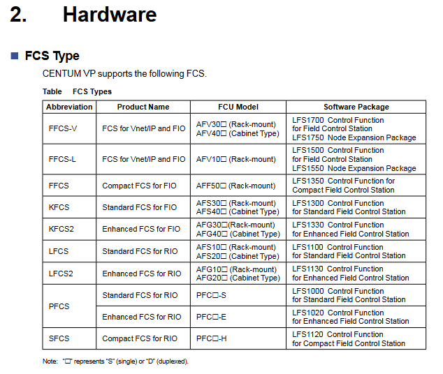
2. FCS model classification (8 core models)
Model Abbreviation Product Name FCU Model Core Software Package
FFCS-V Vnet/IP and FIO specific FCS AFV30 (rack mounted), AFV40 (cabinet mounted) LFS1700 control function package, LFS1750 node expansion package
FFCS-L Vnet/IP and FIO specific FCS AFV10 (rack mounted) LFS1500 control function package, LFS1550 node expansion package
FFCS FIO Compact FCS AFF50 (Rack mounted) LFS1350 Compact Control Function Package
KFCS FIO standard FCS AFS30 (rack mounted), AFS40 (cabinet mounted) LFS1300 standard control function package
KFCS2 FIO Enhanced FCS AFG30 (rack mounted), AFG40 (cabinet mounted) LFS1330 Enhanced Control Function Package
LFCS RIO standard FCS AFS10 (rack mounted), AFS20 (cabinet mounted) LFS1100 standard control function package
LFCS2 RIO Enhanced FCS AFG10 (rack mounted), AFG20 (cabinet mounted) LFS1130 Enhanced Control Function Package
PFCS/SFCS RIO Standard/Compact FCS PFC - S/E/H (Rack mounted) LFS1000/LFS1020/LFS1120 Control Function Package
Note: represents "S" (single redundancy) or "D" (double redundancy)
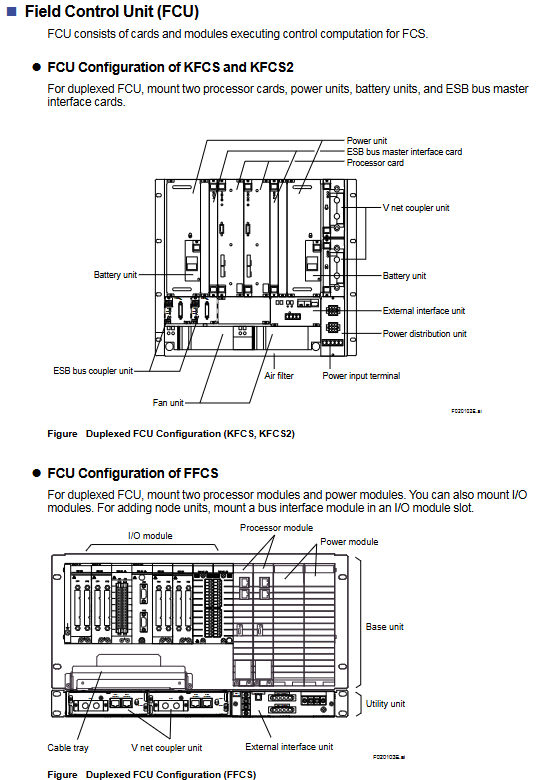
Detailed explanation of hardware composition
1. Core components
FCU (Field Control Unit): Core computing unit, including processor module, power module, and bus interface module. The dual redundant configuration requires the installation of 2 sets of processors, power supply, and bus interface components
NU (Node Unit): Signal processing unit, including ESB/ER bus interface module, I/O module, power module, divided into local nodes (ESB bus) and remote nodes (ER bus)
Communication bus:
ESB bus: connects FCU with local nodes, supports dual redundancy, and has a maximum transmission distance of 10m
ER bus: connects local and remote nodes, supports dual redundancy, uses Ethernet compatible coaxial cables, and can expand distance through optical relays
Optical ESB bus: only compatible with FFCS-V, supports chain/star topology, with a maximum transmission distance of 50km
HKU (House Keeping Unit): monitors the cabinet environment (temperature, fan status) and FCS's own status, including HKU main unit, PDU (power distribution unit), fan power supply unit, etc
2. Classification of I/O modules (FIO/RIO specific)
Module type represents model, core specifications
Analog I/O module AAI141 (4-20mA input) 16 channels, non isolated; Supports HART communication version (AAI141-H)
Analog I/O module AAI543 (4-20mA output) 16 channels, isolated; Supports HART communication version (AAI543-H)
Temperature input module AAT141 (TC/mV) 16 channels, isolated; Supports 8 types of thermocouples
Temperature input module AAR181 (RTD) 12 channels, isolated; Suitable for RTD types such as Pt100
Digital I/O module ADV151 (24V DC input) 32 channels, isolated; Support pressure clamp terminals
Digital I/O module ADV551 (24V DC output) 32 channels, isolated; Support dual redundancy configuration
Communication module ALF111 (FF-H1) with 4 ports, supporting FOUNDATION fieldbus
Communication module ALP111 (PROFIBUS-DPV1) 1 port, compatible with PROFIBUS device communication
Turbomachinery module AGS813 (servo module) isolation design, suitable for turbo machinery control
Detailed explanation of control functions
1. Classification of functional blocks (5 major categories of core functional blocks)
Function block type, core function, representative model
Adjusting control block analog process control and monitoring PID-STC (self-tuning PID), ONOFF-G (three bit ON/OFF controller)
Sequence control block interlocking, process monitoring and other sequence logic ST16 (sequence table block), LC64 (logic chart block), TM (timer block)
Calculate block analog quantity/contact signal universal calculation ADD (addition), MUL (multiplication), CalcU (universal calculation)
Panel block multifunctional block unified label display INDST2 (dual pointer indicator station), HAS3C (mixed manual station)
Unit instrument block, whole process unit operation control, UTSW (three position switch type), OPSBL (SEBOL type operation)
2. I/O function
Process I/O: Interacting with field device data, including% Z (process I/O/fieldbus I/O),% WW/% WB (communication I/O)
Software I/O: FCS internal virtual data interaction, including:
Internal switches:% SW (common switch),% GS (global switch)
Message output:% AN (alarm message),% OG (operator guide message),% CP (upper computer event message)
3. Control the drawing and scanning cycle
Control drawing properties:
Visualize the connection between I/O and functional blocks, define execution priorities
Support mixed configuration of regulation control and sequence control
Function blocks that can be connected across different control drawings
Scanning cycle:
Basic scan: fixed for 1 second
Medium speed scanning: 200ms/500ms (default 500ms), some models do not support it
High speed scanning: 200ms/500ms (default 200ms), supports direct input of 50ms/100ms/250ms
Redundancy mechanism (dual redundant core design)
1. Redundant coverage range
Hardware redundancy: processor module, power module, Vnet/IP interface, ESB/ER bus, node interface module
Software redundancy: synchronous computing, data backup, seamless switching logic
2. Core redundancy technology (Pair and Spare)
Processor module: Each module contains 2 MPUs, which synchronously execute the same calculation and compare the results in real-time. If there is inconsistency, a switch will be triggered
Standby module: Real time synchronous active module calculation, ensuring seamless switching and no process interruption
Fault recovery: The fault module automatically self diagnoses, transient errors can be restored to standby state, and hardware faults support online replacement
Bus redundancy: The ESB/ER bus operates alternately in dual channels, automatically switches in case of failure, and undergoes regular testing to restore its state
Subsystem communication (supports 9 types of core communication)
Communication type adaptation equipment core purpose
Data exchange between FA-M3 communication Yokogawa FA-M3/FA500 controllers
Modbus Communication Yokogawa STARDOM, Schneider Modicon Universal Industrial Equipment Communication
MELSEC Communication Mitsubishi MELSEC Series PLC PLC and FCS Data Interaction
PLC-5/SLC 500 Communication Rockwell PLC-5/SLC 500 European and American PLC Integration
YS Communication Yokogawa YS100/YEWSERIES 80 Yokogawa Instrument Direct Connection
FF-H1 Communication FOUNDATION Fieldbus Device Fieldbus Device Integration
Key issue
Question 1: What is the core design of the dual redundancy architecture for CENTUM VP FCS? How to achieve high availability of 99.99999%?
answer
Core redundancy design: Adopting the "Pair and Spare" technology, each processor module is equipped with 2 MPUs, which synchronously execute the same control calculations and compare the results in real time; A dual redundant configuration that covers all hardware aspects such as processors, power supplies, communication buses, and I/O modules simultaneously.
High availability implementation path:
Calculation verification: When the calculation results of MPU1 and MPU2 are inconsistent, it is judged as a "calculation exception", and the active processor module seamlessly switches to the standby module;
Seamless switching: The standby module synchronizes real-time active module data and computing status, with no process interruption during switching;
Fault self diagnosis: The fault module automatically detects the type of fault, and transient errors can be restored to standby state. Hardware faults support online replacement;
Bus redundancy: The ESB/ER bus operates alternately in dual channels, with regular testing of recovery capabilities and automatic switching in case of failure;
Hardware guarantee: ECC memory automatically corrects bit errors, WDT (watchdog timer) monitors software failures, further reducing the risk of failure.
Question 2: What flexibility does the control function of CENTUM VP FCS have? How to adapt to control requirements of different scales and types?
answer
The flexibility of control functions is reflected in three aspects:
Flexible combination of functional blocks: covering 5 categories of functional blocks including regulation control (PID, ONOFF, etc.), sequence control (ST16, LC64, etc.), calculation (ADD, CalcU, etc.), panel display, etc., supporting on-demand combination;
Control drawing features: Supports cross drawing function block connection, adjustment, and sequence control mixed configuration, and can define control logic according to process units;
Scanning cycle options: basic (1s), medium speed (200ms/500ms), high speed (200ms/500ms) scanning cycle, suitable for different response speed requirements.
Adaptation methods for different scenarios:
Small system: Choose compact FCS (such as FFCS, SFCS), paired with basic functional blocks (such as PID, TM) to simplify configuration;
Large scale system: Select enhanced FCS (such as KFCS2, LFCS2), support multi control drawing interconnection, high-speed scanning, and adapt to complex processes;
Continuous control: mainly based on the adjustment control block (PID-STC), combined with the calculation block to achieve parameter correction;
Sequence control: mainly based on ST16 (sequence table) and LC64 (logic diagram), adapted to interlocking and start stop processes;
Batch control: Implement batch operations for the entire unit through unit instrument blocks (U-TSW, OPSBL).
Question 3: How does the hardware composition and communication capability of CENTUM VP FCS support distributed deployment and multi device integration?
answer
Distributed deployment support:
Hierarchical design of node units: Local nodes (ESB bus) are connected to FCUs nearby, while remote nodes (ER bus) can be deployed near field devices, with distance extended through optical relays or wireless communication;
Optical ESB bus extension: FFCS-V supports optical ESB bus, with a maximum transmission distance of 50km in chain/star topology, suitable for large-scale factory deployment;
Compact installation feature: Can be installed in IEC Zone 2/Class I Div.2 hazardous areas, reducing cable routing costs.
Multi device integration capability:
Fieldbus support: compatible with digital fieldbuses such as FOUNDATION fieldbus (ALF111 module), PROFIBUS-DPV1 (ALP111 module), etc;
Subsystem communication: Supports 9 types of communication protocols such as Modbus, MELSEC, PLC-5, etc., and is compatible with Mitsubishi, Rockwell and other brands of PLCs, frequency converters, analyzers and other equipment;
Open interface: Vnet/IP bus supports third-party Ethernet devices, reducing integration costs;
Communication redundancy: Subsystem communication supports dual redundancy configuration to ensure reliable data transmission.
- ABB
- General Electric
- EMERSON
- Honeywell
- HIMA
- ALSTOM
- Rolls-Royce
- MOTOROLA
- Rockwell
- Siemens
- Woodward
- YOKOGAWA
- FOXBORO
- KOLLMORGEN
- MOOG
- KB
- YAMAHA
- BENDER
- TEKTRONIX
- Westinghouse
- AMAT
- AB
- XYCOM
- Yaskawa
- B&R
- Schneider
- Kongsberg
- NI
- WATLOW
- ProSoft
- SEW
- ADVANCED
- Reliance
- TRICONEX
- METSO
- MAN
- Advantest
- STUDER
- KONGSBERG
- DANAHER MOTION
- Bently
- Galil
- EATON
- MOLEX
- DEIF
- B&W
- ZYGO
- Aerotech
- DANFOSS
- Beijer
- Moxa
- Rexroth
- Johnson
- WAGO
- TOSHIBA
- BMCM
- SMC
- HITACHI
- HIRSCHMANN
- Application field
- XP POWER
- CTI
- TRICON
- STOBER
- Thinklogical
- Horner Automation
- Meggitt
- Fanuc
- Baldor
- SHINKAWA
- Other Brands
- UniOP
- KUKA
- Iba
-
 ELAU DB-5 Distribution HW 5104 Servo System
 -
 Touchstar 10K TS10KCC0CEMP Industrial Touch Panel
 -
 Beckhoff CX2030-0125 Embedded PC PLC
 -
 Parker Hannifin HID5CS/S4 HIDRIVE 5A Servo Drive
 -
 Yaskawa ACE-P300-TH5 Servo Drive with Profibus
 -
 Omron Sysmac SCY-P0 13E Sequencer Controller
 -
 Saia Burgess PCD4.M120 PCD4.M12 Central Controller
 -
 Schneider Electric TSX3722101 Modicon Micro PLC
 -
 Siemens Micromaster 440 6SE6440-2AD25-5CA1 Inverter
 -
 SICK DL50-P1123 Distance Sensor
 -
 Yaskawa SGDH-04AE-OY Servo Driver 200V 400W
 -
 Cincinnati Milacron 3-542-1203A Circuit Board Module
 -
 Allen-Bradley 1756-EN2T EtherNet/IP Communication Module
 -
 OMRON CS1H-CPU66-V1 Programmable Logic Controller
 -
 ABB SACE TMAX S6N 630 Molded Case Circuit Breaker
 -
 Weidmuller IE-SW-VL16-16TX 16-Port Ethernet Switch
 -
 Schneider PowerLogic CM4250 Circuit Monitor
 -
 Sacmi IDPM IDMP1.A SMC 085.16.982 Control
 -
 Omron C120-LK202-EV1 Host Link Unit
 -
 Omron FQ2-S15050F Smart Camera Vision System
 -
 OMRON CJ1G-CPU44H Programmable Logic Controller
 -
 SIEMENS KTP600 HMI 6AV6 647-0AD11-3AX0 Touch Panel
 -
 OMRON CS1G-CPU45H EV1 Programmable Logic Controller
 -
 Omron C200HG PLC System C200H-ID212 C200H-OC226
 -
 ROBOSYSTEM IOG4AX-HD-100 IOG-HD Motion Controller
 -
 Datalogic SG4-S3-080-PP-W Safety Light Curtain
 -
 Omron NS12-TS01B-V2 Interactive Display
 -
 Esto Electronic E.CGT-405-42TE PLC Rack
 -
 Siemens 7ED62 Static Three Phase Counter
 -
 Oemer QCAVS 100 LBE AC Square Frame Servo Motor
 -
 Schneider Electric TM262M25MESS8T Motion Controller
 -
 Eaton Moeller MFD-CP8-ME Power Supply
 -
 Pro-face PL-5700T1-24VDC Industrial Panel PC
 -
 GE Fanuc IC693APU300J High Speed Counter
 -
 Fuji Electric Micrex-F FPU080S PLC Module
 -
 Automation Direct GS2-45P0 AC Drive
 -
 Omron 3G3MV-C4015 V1000 Inverter
 -
 Vacon NXI01055A2T0CSS Industrial Inverter
 -
 Saia Burgess PCD4.M240 Central Controller Module
 -
 Yaskawa SGDH-10DE Sigma II Servo Drive
 -
 Stober EK501USOM140 Servo Motor and Drive
 -
 SCE M68-2000/4 CNC Controller and I/O Board
 -
 Omron SP10-PR001-V1 PLC Programming Console Specs
 -
 VACON NXI01055A2T0CSSA Industrial AC Drive
 -
 OMRON SYSMAC SCY-P1 Sequencer Controller PLC
 -
 SEL-2440 DPAC Discrete Programmable Controller
 -
 BIVIATOR CI3098 CPU Encoder Module Industrial Control Unit
 -
 Siemens 6FC5371-0AA10-0AA2 SINUMERIK NCU 710.2
 -
 KOLLMORGEN SERVOSTAR S70601-NA High Performance Servo Drive
 -
 OMRON C200HW-PCU01 Fastnet PCMCIA LAN Communication Unit
 -
 ibaFOB-2io-D Two-Channel Fiber Optic Input Output Card
 -
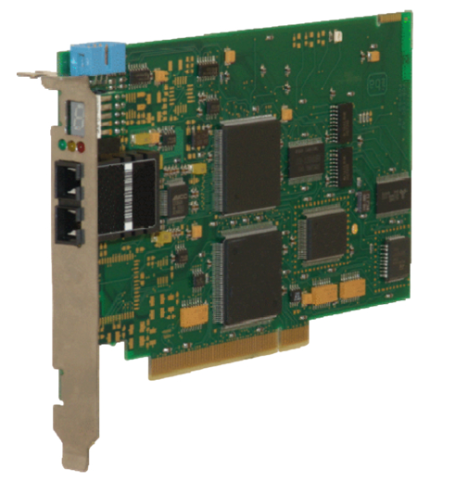
 ibaFOB-4io-D Four-Channel Fiber Optic Input Output Card
 -
 ibaFOB-io-S Single-Channel Fiber Optic Input Output Card
 -
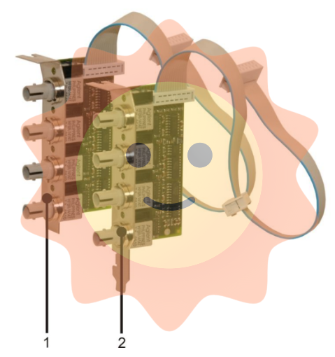
 ibaFOB-4io-S Four-Channel Fiber Optic Input Output Card
 -
 ibaFOB-4o Four-Channel Fiber Optic Output Interface Card
 -
 ibaFOB-4i-S Enhanced Four-Channel Fiber Optic Input Card
 -
 ibaFOB-4i Four-Channel Fiber Optic Input Interface Card
 -
 ibaFOB-io Fiber Optic Interface Card for iba Systems
 -
 SM128V VMEbus Interface Card for Industrial Data Acquisition
 -
 ibaLink-SM-128V-i-2o VMEbus Fiber Optic Interface Board
 -
 GE Fanuc IC693MDL632 125V DC Input Module 8 Points
 -
 GE Fanuc IC693MDL241 24V AC/VDC Input Module 16 Points
 -
 GE Fanuc IC693MDL240 120V AC Input Module 16 Points
 -
 GE Fanuc IC693MDL231 240V AC Isolated Input Module
 -
 GE Fanuc IC693MDL230 120V AC Isolated Input Module
 -
 GE Fanuc IC693MDL654 5/12 VDC 32-Point Input Module
 -
 GE Fanuc IC693MDL653 24 VDC 32-Point Input Module
 -
 GE Fanuc IC693MDL648 48 VDC 16-Point Input Module
 -
 GE Fanuc IC693MDL646 24 VDC 16-Point Input Module
 -
 GE Fanuc IC693MDL634 24 VDC Input Module 8 Points
 -
 GE IM 3100 D 1007722 Control Module
 -
 GE IM0146B Industrial Circuit Board
 -
 GE IM0059E0-10070 Interface Board
 -
 GE IM0094C Industrial Control Board
 -
 GE IC200PNS002-AB VersaMax PROFINET Scanner
 -
 GE F650BFBF1G0HI Feeder Protection Relay
 -
 GE TPR5616NRHC Protection Relay
 -
 GE D6P3KH Digital Protection Relay
 -
 GE F650BABF2G0HIS Feeder Protection Relay
 -
 GE F650BADF2G1HIR Feeder Protection Relay
 -
GE F650BABF2G1HI6 Digital Bay Controller
-
 GE Multilin 745-W2-P1-G1-H-I-A-R-E Transformer Protection Relay
 -
 GE 100BASE-T Industrial Ethernet Interface
 -
 GE Multilin 350-E-P1-S1-H-S-E-C-N-2E-D-H Feeder Protection System
 -
 GE F650MXCF1G1HI6 Bay Controller
 -
 GE MM300-GEHD2CAB Motor Management Relay
 -
 GE MMS35-621-1-00 Motor Management System
 -
 GE 100BASE-T Ethernet Communication Module
 -
 GE F650MFCF1G1HI6 Feeder Protection Relay
 -
 GE CK13BA300 Control Module
 -
 GE W2-P1-G1-H Industrial Control Unit
 -
 GE PIB315B Power Interface Board
 -
 GE 343L695VAGIRHC Multi-Function Relay
 -
 GE Multilin B90N05HKHF8NH6 Bus Differential Protection
 -
 GE ZX3SC0204N-930 Intelligent Control Module
 -
 GE PIB504 Process Interface Board
 -
 GE D20MX Remote Terminal Unit
 -
 GE T60UJ3HKHF8NH6 Transformer Protection Relay
 -
 GE ZG3SA02041-58S600X Motor Protection Relay
 -
 GE ZG3SA02041-58S Motor Protection Relay
 -
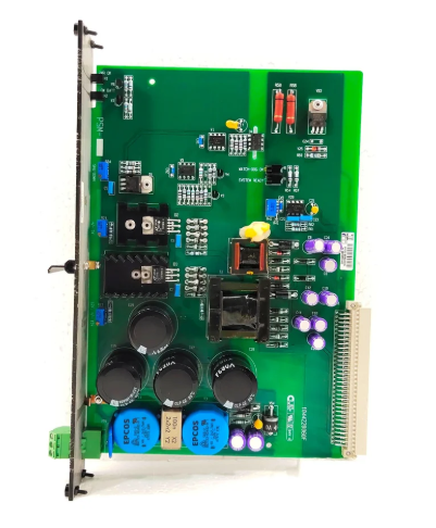
 ABB DSDX 452 L Remote Input Output Module
 -
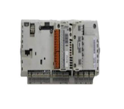 ABB RDCU-02C Drive Control Unit
 -
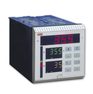 ABB COMMANDER 350 Process Controller
 -
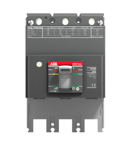 ABB Tmax XT4S 250 Molded Case Circuit Breaker
 -
 DEIF MALLING 8027.90 Industrial Control Unit
 -
 DEIF DCP2-2410 Power Supply Module
 -
 DEIF FAS-2N Synchronizer
 -
 DEIF MALLING 827.54 Processor Module
 -
 DEIF DU-2/MKIII Display Unit
 -
 DEIF DRW-2 Reverse Power Relay
 -
 DEIF 827.4 Power Management Module
 -
 DEIF 1044220060F Mains Measurement Module
 -
 DEIF 1044220190G Remote Display Module
 -
 DEIF 1044220140C AGC 200 Display Module
 -
 DEIF BRW-1-NB Remote Display Unit
 -
 DEIF MALLING 827.52 Industrial Control Unit for Automation Systems
 -
 DEIF BRW-2 Industrial Relay Module for Control Systems
 -
 DEIF 1044220080D Power System Control Module Industrial Automation
 -
 DEIF 1044220100F Controller Module for Generator Control Systems
 -
 DEIF DU-300 Voltage Monitoring Relay Industrial Protection Unit
 -
 DEIF 1044220060F I/O Extension Module
 -
 DEIF 1044220150C Interface Module
 -
 DEIF GCU 100 Engine Control Unit
 -
 DEIF XDI144-DUAL Marine Indicator
 -
 DEIF 827.41 Multi-line 2 Processor Module
 -
DEIF AGC 146 Automatic Genset Controller
-
 DEIF 1044220080E MDR-2 Display Module
 -
 DEIF MDR-2 Multifunctional Digital Relay


