
YOKOGAWA CENTUM VP System HMI (HIS)
YOKOGAWA CENTUM VP System HMI (HIS)
Core features and hardware composition of HIS
(1) Core design philosophy and characteristics
Ergonomic Design: Adopting the "Simple&Intuitive" concept, unifying icon styles, information layouts, and color schemes, reducing the physical and mental burden on operators, and improving operational comfort and accuracy
Multi monitor support: 1 HIS can connect up to 4 monitors, supports single button switching of monitor display content, can display multiple types of monitoring windows simultaneously, and is suitable for parallel operation in complex scenarios
High speed data update: The data collection and interface update speed is as fast as 1 second, meeting the real-time requirements for manual control of key parameters such as pressure and flow rate
Operational inheritance: compatible with traditional HMI operation logic, supporting touch operation, 8-key control, 64 function keys, reducing operator learning costs
Cross system integration capability: capable of integrating alarm and event data from CENTUM VP, ProSafe RS (Safety Instrumented System), STARDOM (Network Control System), and PRM (Field Device Management Package)
Remote operation and maintenance support: Remote operation and monitoring can be achieved through the intranet, and the remote PC can use the same operation window as the local HIS (except for some functions)
(2) Detailed explanation of hardware composition
1. Core hardware configuration
Host: Pre installed with Microsoft Windows system (such as Windows 7 SP1), supports widescreen displays, and has multi interface expansion capabilities such as PCI, USB, Ethernet, etc
Operation keyboard: two types, both using flat key design, supporting one click operation, suitable for high-frequency use in industrial scenarios
Keyboard type, core key layout, special design
8-key control type with 64 function keys, mode selection switch, operation confirmation key, data input key, and 8 control keys with touch sensors adapted for multi loop parallel control
1-key control type with 64 function keys, mode selection switch, operation confirmation key, data input key, and 1 core control key simplifies operation logic and is suitable for single loop control
Monitor: Supports multiple linkage (up to 4), compatible with widescreen models, supports high-resolution display, ensuring clear presentation of graphics and data
Core functions of operation and monitoring
(1) Overall display layout
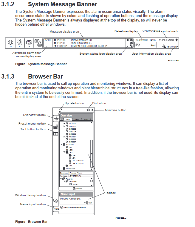
The HIS display interface adopts a fixed three part structure to ensure unified operation logic and no window obstruction:
System message bar: permanently displayed at the top, cannot be hidden, core functions include:
Visual alarm prompt: Display the alarm status through button color changes and flashing
Basic information display: date and time, current username, system status icon, advanced alarm filter name
Alarm message preview: scroll display key alarm information (such as equipment failure, parameter exceeding)
Browser Bar: Foldable area on the left, with core functions including:
Window Call: Tree based Display of Operation Monitoring Window List and Factory Hierarchical Structure
Quick Tools: Preset Menu Toolbox, Tool Button Toolbox, Window History
Flexible configuration: supports minimizing hiding and does not occupy monitoring space
HIS desktop area: the core workspace, using a three-level structure of "container window frame view":
View: Single monitoring unit (such as graphical view, trend view)
Framework: Supports multiple views (up to 4 per frame), supports tab switching
Container window: the outermost "canvas" that supports multiple frames and allows for free layout
(2) Core operation monitoring window
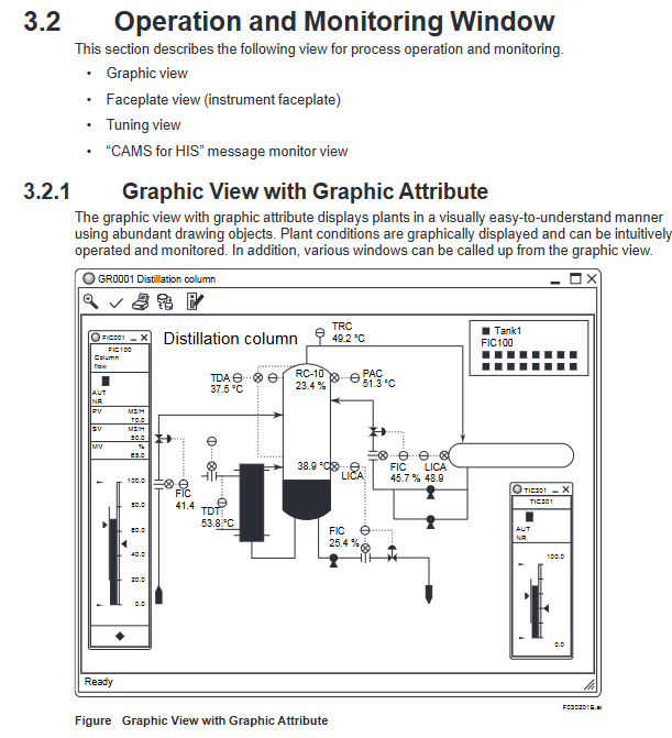
1. Graphic view (two major attributes)
Attribute Type Core Function Key Features
Visual display of factory layout and equipment status using graphic properties as drawing objects. 1. Supports rich drawing elements such as valves, pumps, and storage tanks
2. Intuitively present device connection relationships and real-time parameters (such as temperature and flow)
3. Other operation windows can be directly called from the view
Control attributes to display function block status in the dashboard. 1. Supports two panel sizes: 8 large sizes/16 small sizes for parallel display
2. Can mix and display panels of different sizes
3. Real time presentation of functional block operation modes (AUT/NR, etc.) and parameter values
2. Panel View (Instrument Faceplates)
Core purpose: Compact display of key information of a single functional block, including data values, operating modes, alarm states, input and output parameters
Supporting module types: covering more than 10 core modules such as PVI input indication, PID controller, MLD manual loader, MC-2 dual position motor control, ALM-R alarm block, etc
Display elements: tag name/comment, block mode/status, alarm status, engineering unit, parameter scale bar, limit alarm tag (high high/high/low/low low)
3. Trend View
Core function: Display process data changes in time series, support historical data tracing and trend comparison
Key parameters:
Data capacity: Supports simultaneous display of 8 or 16 data entries
Split screen mode: Three tiled modes (pen split/simulation discrete split/trend data reference mode split)
Data export: Supports graphic copying (excluding window borders), numerical data copying (including labels, time, values, status, etc.), and can be pasted into tools such as Excel
Flexible configuration: Supports displaying data with different sampling periods on the same screen, and can adjust the magnification ratio of the timeline and data axis
4. Tune View
Core function: Display the tuning parameters and trends of a single instrument, support parameter adjustment
Display content:
Basic parameters: PV (process variable), SV (set value), MV (operating variable), operating mode, alarm status
Tuning parameters: proportional (P), integral (I), derivative (D) parameters, limit settings (HH/PH/ML/LL, etc.)
Trend curve: Real time display of PV, SV, MV trends over time, supporting axis scaling
CAMS for HIS message monitoring (core alarm management tool)
Following the EEMUA 191 alarm management standard, solving the problem of alarm overflow, the core functions include:
Multi system alarm integration: Centralized display of alarms and events for CENTUM VP, ProSafe RS, STARDOM, and PRM
Intelligent filtering function:
Filtering/Sorting: Basic filtering (process/system alarms), user-defined filtering, temporary filtering
Eclipsing: Integrating duplicate alarms of the same label into a single line display
Shelving: Manually/automatically move non essential alarms to temporary areas
Load Shedding: Automatically activates preset filters when a large number of sudden alarms occur
Suppression: Suppress redundant messages by alarm group/site
Alarm value-added information: configurable monitoring purposes (safety/environmental/economic), target user groups, response time, priority, root cause analysis, processing flow, etc
Alarm setting value management:
Save the set values of the engineering phase as the baseline values, and support comparing the baseline values with the current values
Display differences in set values, support benchmark values to override current values or vice versa
Archive difference setting values for easy traceability and adjustment of records
Long term data archiving: supports long-term storage of alarm history data, which can be traced through a history viewer
(3) Auxiliary support function
1. Report function
Core purpose: Automatically generate daily/monthly reports, support production data analysis and compliance records
Tool dependency: Based on Microsoft Excel, supporting template reuse and custom creation
Imported data types: settlement data (mean/total/maximum/minimum), trend data, historical messages, tag information, real-time process data, batch data
Printing method:
Automatic printing: timed triggering, sequence message triggering
Manual printing: triggered by function keys, graphic view buttons, Excel direct printing, VB program call
Remote printing: Other PCs within the network can print reports through Excel
2. Remote operation and monitoring server
Deployment Architecture: Remote PC (Client) → Intranet → Remote Operations Server → CENTUM VP Control Network
Core function: Remote implementation of operation monitoring and engineering configuration, using operation windows consistent with local HIS
Reliability requirement: The control network needs to be equipped with at least one standard HIS to ensure real-time performance and redundant backup
3. CENTUM Desktop
Dedicated operating environment: Hide Windows redundant features (such as desktop icons, unrelated start menu items, shutdown options)
Core value: Focus on production operations, avoid misoperation of Windows system functions, and enhance operational security
4. HIS Utility tool
Purpose: Configure HIS operating environment, support multi tab settings
Core configuration items:
User management: Add/delete users, configure automatic login (only in CENTUM authentication mode)
Operation configuration: keyboard type, mouse increase/decrease mode, trend collection pen allocation
Security Policy: Set HIS Security Rules
Special configuration: CAMS for HIS parameters, remote operation and maintenance parameters, OPC interface parameters
System management and security control
(1) System management window
Window Name Core Usage Key Features
Overview of System Status: Monitor the status of all stations and communication equipment within the monitoring domain. 1. Use icons to visually display the operational status of FCS, HIS, BCV, and other equipment
2. Support calling the system maintenance window
3. Domain definition: All sites connected by the control bus (Vnet/VNet/IP)
System alarm view displays hardware/communication error alarms. 1. The alarms are arranged in reverse chronological order (latest first)
2. When the alarm is triggered, it is accompanied by buzzing and flashing prompts
3. Automatically switch to CAMS message monitoring when CAMS takes effect
FCS status display view shows FCS hardware configuration and operational status. 1. Display site information, hardware architecture, and communication bus status
2. Color identification of normal/abnormal status of equipment
3. Support starting/closing the control station
HIS status display view shows HIS hardware configuration and operating status. 1. Display host information and hardware interface status (such as Ethernet, USB)
2. Monitor hardware parameters such as fans, hard drives, temperature, etc
3. Support switching control bus effectiveness
HIS settings window configuration HIS operating parameters 1. 18 configuration tags (display, printer, buzzer, alarm, trend, etc.)
2. Support multi monitor settings, customizable function keys, and report parameter configuration
3. Some configurations require a restart of HIS to take effect
(2) Security control system
Adopting a dual layer architecture of "CENTUM dedicated security+Windows IT security" to ensure operational and data security:
1. CENTUM dedicated security
User three attributes:
Username: Unique identifier for the operator, associated with operation logs and password
User group: Define the scope of operation monitoring (such as specific FCS, windows, factory areas)
User permissions: subdivided operation levels, default 3 levels of standard permissions+7 levels of custom permissions
Permission level monitoring permission operation permission engineering permission
S1 (ordinary operator) present or absent
Is S2 (Senior Operator) available
S3 (Engineer) Yes Yes Yes Yes
U1-U7 (custom) configurable configurable configurable
Fine grained control granularity:
Function block level: Modification of important function block parameters requires secondary confirmation, and operation permissions can be temporarily disabled
Window level: Restrict operations such as modifying graphical view dashboards and adjusting trend view parameters
Tag level: Tag priority (important/normal/auxiliary 1/auxiliary 2), differentiated alarm processing
Advanced security features:
User lockout: Multiple password errors trigger system alarm, which can lock illegal login accounts
Password expiration: password expiration period can be set, with a 14 day reminder before expiration
Prohibition of duplicate passwords: Historical passwords cannot be used when changing passwords
Automatic logout: Automatically log out after no operation timeout
2. Windows IT Security
Security Model: Provides 3 models to adapt to different scenarios
Model Type Core Defense Scope Applicable Scenarios
Traditional models lack reinforcement and prioritize compatibility with legacy products for upgrading old systems, requiring compatibility with old devices
Standard model defense against network attacks and direct operational attacks in conventional industrial scenarios, balancing security and compatibility
Strengthen model defense against network attacks, direct operation attacks, and high security scenarios such as component/data theft (such as petroleum and chemical industries)
Authentication mode:
Windows authentication mode: integrates Windows account and HIS operation permissions, supports domain management and single sign on
Single sign on method: Windows login automatically synchronizes HIS login; Or the system can automatically log in to Windows and HIS can be started with the lowest privilege
Communication control: Restrict communication types and ports through Windows firewall and DCOM settings to defend against network attacks
Applicable scenarios and core values
(1) Applicable industries and scenarios
Industry scope: Process industries such as petroleum refining, chemical, steel, food, and electricity
Core scenario:
Real time operation monitoring: device start stop, parameter adjustment, status observation
Alarm management: Multi system alarm integration, critical alarm screening, alarm processing guidance
Data tracing: trend data query, historical alarm archiving, production report generation
Remote operation and maintenance: remote factory monitoring, remote parameter adjustment, troubleshooting
(2) Core values
Improve operational efficiency: ergonomic design+multi window parallel display, reducing operational steps and switching costs
Ensuring system security: dual layer security control+refined permissions to prevent illegal operations and data leakage
Reduce the difficulty of operation and maintenance: remote operation and maintenance+intelligent alarm management, reducing on-site duty and fault handling time
Strengthen data support: report function+trend analysis, providing data basis for production optimization

- OMRON
- ABB
- General Electric
- EMERSON
- Honeywell
- HIMA
- ALSTOM
- Rolls-Royce
- MOTOROLA
- Rockwell
- Siemens
- Woodward
- YOKOGAWA
- FOXBORO
- KOLLMORGEN
- MOOG
- KB
- YAMAHA
- BENDER
- TEKTRONIX
- Westinghouse
- AMAT
- AB
- XYCOM
- Yaskawa
- B&R
- Schneider
- KONGSBERG
- NI
- WATLOW
- ProSoft
- SEW
- ADVANCED
- Reliance
- TRICONEX
- METSO
- MAN
- Advantest
- STUDER
- DANAHER MOTION
- Bently
- Galil
- EATON
- MOLEX
- DEIF
- B&W
- ZYGO
- Aerotech
- DANFOSS
- Beijer
- Moxa
- Rexroth
- Johnson
- WAGO
- TOSHIBA
- BMCM
- SMC
- HITACHI
- HIRSCHMANN
- Application field
- XP POWER
- CTI
- TRICON
- STOBER
- Thinklogical
- Horner Automation
- Meggitt
- Fanuc
- Baldor
- SHINKAWA
- Other Brands
- UniOP
- KUKA
- Iba
- Beckhoff
-
 Basler D90 96801 100 PCB Card
 -
 Basler XR2002F Voltage Regulator (110 VAC, 48-480 Hz)
 -
 Basler SR8A-2B14B3A Regulator
 -
 Basler 9561500100 Module
 -
 Basler DECS-400 BE1-11 System
 -
 Basler DECS-100-B15 Excitation Control
 -
 Basler SCP 210 Frequency Controller
 -
 Basler SR4A-2B15B3A Static Voltage Regulator
 -
 Basler BE1-32R Power Relay
 -
 Basler PIA2400-17GM Power Interface Adapter
 -
 Basler MVC 232 Manual Voltage Control Module
 -
 Basler SSR 32-12 Static Voltage Regulator
 -
 Basler 5MW AVR Generator Voltage Regulator
 -
 Basler VR63-4B Voltage Regulator
 -
 Basler DECS-100-A05 AVR for Engine Generator
 -
 Basler DECS-100-B15 Automatic Voltage Regulator
 -
 Basler BE1-32R Directional Power Relay
 -
 Basler BE1-87B Differential Relay
 -
 Basler UFOV 260A Protective Module
 -
 Basler 9-2614-02-100 PCB Rev M
 -
Basler DECS-100-B15 Digital AVR
-
 Basler 9284900103 PS DECS-400N
 -
 Basler D4N3H1U Intertie Protection
 -
 Basler DECS-100-B15 A15 AVR
 -
 Basler KR4F Voltage Regulator
 -
 Basler BE26434 T14 Transformer
 -
 Basler SR8A-2B15B3A Regulator
 -
 Westinghouse 774B472A12 AR Relay
 -
Basler DECS-100-B15 AVR
-
Basler XR2002F Regulator 110V
-
Basler SR125-E Static Regulator
-
 Basler SSR 125-12 Regulator
 -
 Basler MOC2599 Motor Pot
 -
 Basler BE1-DFPR Feeder Relay
 -
 Basler CBS 305 Current Boost
 -
 Basler BE1-25 AutoSync
 -
 Basler MVC 300 Voltage Control
 -
 Basler BE3-25A AutoSync
 -
 Basler KR7FF Static Regulator
 -
 Basler 90-49000-100 Regulator
 -
 Basler 880 kVA Dry Type Transformer Specs
 -
 Basler Electric BE1-25 Sync-Check Relay Specs
 -
 Basler SSR 125-12 Voltage Regulator Specs
 -
 Basler Electric BE1-851 Overcurrent Relay Review
 -
Basler Electric 149D930G02 Control Sub-Assembly
-
 Basler Electric BE1-81O/UT Frequency Relay Specs
 -
 Basler Electric BE1-51/27C Overcurrent Relay
 -
 Basler Electric 149D956G02 Industrial Component
 -
Basler Electric BE1-51A Overcurrent Relay Specs
-
 Basler Electric BE1-40Q Loss of Excitation Relay
 -
 Basler DECS-200 Excitation Control System
 -
 Basler DECS-200 Voltage Regulator 56-277V AC / 125V DC
 -
Basler BE1-87T Transformer Differential Relay
-
 Basler RDP-110-S1 Protection Relay
 -
 Basler BE1-700V Digital Protective Relay
 -
 Basler BE1-951 Overcurrent Protection System
 -
 Basler DECS-300 Digital Excitation Control
 -
 Basler DECS-200 Digital Excitation Control
 -
 Basler DECS-200-1C Excitation Control System
 -
Basler DECS-200-1L Digital Excitation Control
-
 Basler Electric BE1-GPS Generator Protection System
 -
Basler Electric DECS-200-1C Digital Excitation Controller
-
 Basler Electric DECS125-15 Excitation Control with Power Module
 -
 Basler Electric BE1-87G Differential Relay
 -
 Basler Electric BE1-11 Protection System I5A3M2P2N0EA00
 -
Basler Electric DECS-200-1C Excitation Control System
-
Basler Electric BE1-11g Generator Protection Relay
-
Basler Electric DECS 125-15-B2C1 V2.0.9 Excitation Control
-
 Basler Electric BE1-81O/UT3ED1JA7N2F Frequency Relay
 -
Basler Electric BE1-81O/UT3EE1YB7N1F Frequency Relay
-
 Basler Electric DECS-200-1L Digital Excitation Control System
 -
Basler DECS125-15-B2C1 Excitation Control
-
 Basler 9507900205 SSR Retrofit Voltage Regulator
 -
 Basler BE2000E Digital Voltage Regulator
 -
 Basler BE1-GPS Generator Protection System
 -
Basler DECS-250-CN1CN1N Digital Excitation Control
-
 Basler DGC-2020 Genset Controller
 -
 Basler BE1-81O UT3ED1LA7N0F Frequency Relay (Variant)
 -
 Basler BE1-81O UT3EE1YA9S0F Frequency Relay (Variant)
 -
Basler BE1-81O Over/Under Frequency Relay
-
Basler DECS125-15 Digital Excitation Control
-
Basler Electric BE1-951 Overcurrent Protection System
-
 Basler Electric BE1-700V Digital Protective Relay
 -
 Basler Electric APR63-5 Automatic Voltage Regulator
 -
Basler Electric BE1-851 Overcurrent Protection System
-
Basler Electric DECS-250-LN1SN1N Excitation Control
-
 Basler Electric BE1-87T Transformer Differential Relay
 -
Basler Electric DECS-200-1L Excitation Control System
-
 Basler Electric 9310300100 DECS-300 Excitation Control
 -
 Basler Electric SSE-N 125-4.5KW Shunt Exciter Regulator
 -
 Basler Electric DGC-2020HD-5NS1DNSBA Genset Controller
 -
Basler Electric BE1-81-O/UT3EE1JB7N1F Frequency Relay
-
Basler Electric BE1-81T1EE1WA0N1F Frequency Relay
-
 Basler Electric BE1-25M1EA6PN5R1F Sync-Check Relay
 -
 Basler Electric BE1-GPS Generator Protection System
 -
Basler Electric DECS-250-LN1SN1N Excitation Control Rev V
-
 Basler Electric DECS-250-CN2CN1N Excitation Control
 -
Basler Electric BE1-50/51B-207 Overcurrent Relay
-
Basler Electric DECS-300-C0N0 Excitation Control System
-
Basler Electric DECS-200 Digital Excitation Control System
-
Basler Electric DECS-250-LN1CN1N Excitation Unit
-
Basler Electric DECS-250 LN2SA1D Excitation Unit Specs
-
Basler Electric BE1-87T Transformer Relay Review
-
Basler Electric BE1-11 Protection System
-
Basler Electric BE1-GPS100-E4N1H1N Protection System
-
 Allen-Bradley 442G-MABH-R Safety Module
 -
 Beckhoff CX1030-0111 PLC Assembly Profile
 -
 FANUC IC693CPU364 PLC Module
 -
 Orange Denmark Type 200816 220 PLC Specs
 -
 OMRON C200H-SNT31 Sysmac PLC Module
 -
 Allen Bradley 20AB022A3AYNANC0 PowerFlex 70
 -
 OMRON C200HW-PCU01 Position Control Unit
 -
 ABB AO845A-eA Analog Output Module
 -
 OMRON CJ1M-CPU22 CPU Unit
 -
 Allen Bradley 100-E265ED11 Contactor
 -
 Honeywell 51304511-100 Interface Module
 -
 SOLEXY BXF3S0101N0018 Gateway Module
 -
 OMRON CJ2H-CPU65 CPU Unit
 -
 Automation Direct GS2-45P0 AC Drive
 -
 M68-2000 2-Axis Motion CNC Controller
 -
 OMRON CJ1M-CPU11 V3.0 PLC CPU Unit
 -
 OMRON CJ1W-NC413 4-Axis Positioning Controller
 -
 OMRON 3G2A3-PRO16 Programming Console HMI
 -
 Siemens 3VT8440-2AA04-2GA2 Molded Case Circuit Breaker
 -
 Siemens 3RT5045 Contactor Series
 -
 OMRON C200HS-CPU01-E SYSMAC PLC Controller
 -
 OMRON C500-NC103-E Positioning Control Unit
 -
 OMRON CJ1W-TC001 Temperature Control Unit


