
Konica Minolta CM-3700A-U Plus spectrophotometer
(1) Equipment Introduction
CM-3700A-U Plus is a reflective high-precision fixed spectrophotometer developed specifically for measuring color and color difference in various industrial fields, meeting the high-precision requirements for color quality control in industrial production.
(2) Packaging and Protection
It is necessary to properly store all packaging materials (cardboard boxes, cushioning materials, plastic bags, etc.) used during equipment transportation. As the equipment is a precision measuring instrument, these materials are needed to reduce vibration and impact during subsequent maintenance and transportation; If the packaging materials are lost or damaged, please contact an authorized service agency.
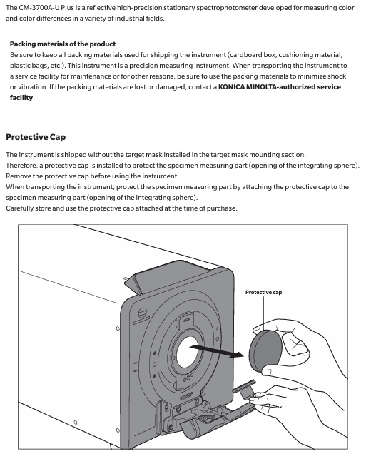
When the equipment leaves the factory, the target mask is not installed at the target mask installation location, but a protective cover is installed to protect the sample measurement component (integrating ball opening). Before use, the protective cover must be removed, and during transportation, the protective cover must be installed. At the same time, the protective cover that comes with the equipment should be stored and used properly.
Konica Minolta CM-3700A-U Plus spectrophotometer
Basic Equipment Information
(1) Equipment Introduction
CM-3700A-U Plus is a reflective high-precision fixed spectrophotometer developed specifically for measuring color and color difference in various industrial fields, meeting the high-precision requirements for color quality control in industrial production.
(2) Packaging and Protection
It is necessary to properly store all packaging materials (cardboard boxes, cushioning materials, plastic bags, etc.) used during equipment transportation. As the equipment is a precision measuring instrument, these materials are needed to reduce vibration and impact during subsequent maintenance and transportation; If the packaging materials are lost or damaged, please contact an authorized service agency.
When the equipment leaves the factory, the target mask is not installed at the target mask installation location, but a protective cover is installed to protect the sample measurement component (integrating ball opening). Before use, the protective cover must be removed, and during transportation, the protective cover must be installed. At the same time, the protective cover that comes with the equipment should be stored and used properly.
Precautions for use
(1) Operating environment
The equipment should be installed and used in an environment with an ambient temperature of 13-33 ° C, a relative humidity of ≤ 80% (at 33 ° C), and no condensation. Exceeding this range will affect the performance of the equipment.
The equipment and standard AC adapter (AC-A312F) are only designed for indoor use and are prohibited from outdoor use to prevent damage to the equipment due to factors such as rainwater.
The equipment is composed of precision electronic components, and disassembly or modification is prohibited as it may cause accidents such as malfunctions, electric shock, and fires; The equipment belongs to the second level pollution level product and is suitable for use in manufacturing environments, laboratories, warehouses, and other places that are not easily exposed to metal dust and condensed water; Simultaneously belonging to Class I overvoltage category products, they need to be connected to circuits that take measures to limit transient overvoltage to a lower level.
Prevent foreign objects from entering the equipment, and use extremely dangerous when the equipment comes into contact with water or metal; Avoid exposing the equipment to direct sunlight or near heating devices to prevent malfunctions caused by high internal temperatures; Avoid equipment experiencing drastic temperature changes and condensation; Prohibit the use of equipment in environments with high dust, smoke, chemical gases, or extreme humidity; The equipment should not be used at an altitude exceeding 2000 meters; Avoid using equipment near strong magnetic fields, such as speakers.
(2) System related
Prevent equipment from experiencing strong vibrations or impacts; Do not pull, forcefully bend, or apply excessive pressure to the connected cables to prevent cable breakage.
The sample measurement port and the interior of the integrating sphere of the equipment are high-precision components of the optical system, which need to be kept clean to avoid impact. When the equipment is not in use, a target mask should be installed and the sample measurement port should be covered.
The equipment and adapter belong to Class B EMC products, which may cause radio interference when used in a home environment. Users need to take appropriate measures to solve this problem; When the device encounters strong external static electricity, the display screen may go black or display abnormally, and communication with external devices may also be interrupted. At this time, the power needs to be turned off and restarted, and when restarting, wait a few seconds after turning off the power before restarting.
The device should be connected to a power source with as little noise as possible; The equipment complies with the "Electrical Equipment for Measurement, Control, and Laboratory Use - Electromagnetic Compatibility (EMC) Requirements - Part 1: General Requirements" (EU Harmonized Standard EN 61326-1:2021), and the consistency verification is conducted under the testing conditions of Konica Minolta in the industrial electromagnetic environment specified in the relevant Harmonized Standard. The performance degradation limit caused by continuous interference in the anti-interference test does not exceed 4 times the Konica Minolta repeatability specification (Δ E * ab).
When the device malfunctions or behaves abnormally, immediately turn off the power, disconnect the adapter plug, and refer to "Troubleshooting" (page 29); When the equipment malfunctions, it is prohibited to disassemble and repair it on your own, and authorized service agencies must be contacted.
(3) Measurement related
Ensure that there is no dust or dirt entering the opening of the device; After long-term use of the equipment, measurement values may deviate due to environmental factors. To ensure measurement accuracy, it is recommended to perform regular white calibration.
(4) White calibration board
The calibration data of the white calibration board should be measured at 23 ° C. To obtain the highest absolute measurement accuracy, calibration and measurement should be carried out at 23 ° C; Avoid scratching or staining the calibration plate with dirt; When installing the calibration board on the sample rack, it is prohibited to move it to prevent scratching; When not in use, cover with a lid to avoid exposure to external light.
(5) Target Mask
Do not touch the inner surface of the target mask (white coating surface) with your hands to prevent it from getting dirty or scratched; When not in use, it should be placed in the accessory storage space of the device to prevent exposure to external light.
(6) Power related
Turn off the power when the device is not in use; Use the designated AC adapter and connect it to a power outlet that meets the requirements; Use AC power supply with rated voltage (within ± 10% range); Ensure that the output plug of the adapter is not short circuited, otherwise it may cause fire or electric shock; Do not connect the adapter to overloaded circuits, and do not cover the adapter with cloth or other materials during use to prevent electric shock or fire; When removing the adapter from the device, first unplug the power cord from the socket, and then unplug the output plug.
Storage, cleaning, transportation, and maintenance
(1) Storage precautions
The equipment should be stored in an environment with a temperature of 0-40 ° C, a relative humidity of ≤ 80% (at 35 ° C), and no condensation. High temperature and humidity environments can affect the performance of the equipment. It is recommended to store it together with desiccants at or near room temperature.
Avoid storing equipment in direct sunlight or near heating devices to prevent malfunctions caused by high internal temperatures; When storing, prevent the device from condensing, and when transporting to the storage location, also be careful to avoid sudden temperature changes that may cause condensation.
Do not store equipment in environments with high dust, smoke, or chemical gases to prevent performance degradation or malfunction; When the device is not in use, a protective cover should be installed to prevent dust from entering the integrating sphere and affecting the measurement accuracy; Do not let the device have the target mask installed for a long time; Do not leave the device in the driver's cabin or trunk of the vehicle to prevent malfunctions caused by temperature and humidity exceeding the allowed storage range.
The white calibration board may change color when exposed to light, and should be covered when not in use; The target mask may change color when exposed to light. When not in use, it should be stored in the accessory storage space of the device to avoid light exposure, scratches, and dust accumulation; When the equipment is not in use for a long time, it should be stored properly in the transport packaging; When operating the opening and closing parts of the attachment storage space, be careful not to pinch it.
(2) Cleaning precautions
When the surface of the equipment is dirty, wipe it with a soft dry cloth, and do not use organic solvents (such as naphtha, diluents) or other chemical reagents for cleaning.
When there is dust or dirt on the lens or receiver window, use a dust blower to remove it, and do not use organic solvents or other chemical reagents; When the interior of the white calibration board, zero calibration box, or target mask (except for the inner white coating surface) is dirty, use a soft, clean dry cloth to wipe it. For dirt that is difficult to remove, use a cloth dipped in ethanol to wipe it. After the cloth is dirty, it needs to be cleaned. Organic solvents or other chemical reagents are prohibited from being used.
When the surface of the white coating on the inside of the target mask or the inside of the integrating sphere is dirty, it is necessary to contact an authorized service agency; If the above methods cannot remove dirt or equipment scratches, contact an authorized service agency; When the equipment malfunctions, it is prohibited to disassemble and repair it on your own, and authorized service agencies must be contacted.
(3) Transportation precautions
Before transporting the equipment, it is necessary to remove the target mask and install a protective cover to protect the sample measuring components (integrating ball opening); The equipment weighs approximately 18kg and needs to be operated by two or more personnel when moving (including transporting) the equipment.
Packaging materials must be used when transporting equipment to reduce vibration and impact; When sending the equipment for repair, the equipment and all accessories must be packaged and sent out.
(4) Maintenance and Inspection
To ensure measurement accuracy, the equipment should be inspected once a year. For specific inspection matters, please contact the nearest authorized service agency of Konica Minolta.
(5) Disposal methods
Equipment, all accessories, and packaging materials must be properly disposed of or recycled in accordance with local laws and regulations to ensure compliance with environmental protection and relevant regulations.
Attachment information
(1) Standard attachments
Attachment Name, Model, Usage, and Precautions for Use
The white calibration board CM-A309 is used for reflectance measurement. When not in use, it needs to be covered to prevent dust accumulation, scratching, and exposure to external light
The zero calibration box CM-A155 is used for reflectance measurement. When using it for zero calibration, it should be installed correctly to avoid falling off due to external force, keep the interior clean, prevent scratching and fingerprint contamination, clean it according to regulations when it is dirty, and replace it if it is damaged and cannot be cleaned
When adjusting the illumination area (sample measurement port size) of the target mask CM-A310/A314 according to the sample, CM-A310 (SAV) has a measurement area of 1 × 3mm and an illumination area of 5 × 7mm. CM-A310 (SAV) must be used for zero calibration or white calibration of CM-A314 (USAV) with a measurement area of 1 × 3mm and an illumination area of 3 × 5mm. When installing, pay attention to the direction and avoid scratching the inner white coating surface. When not in use, place it in the accessory storage space
The AC adapter AC-A312F (ATS036T-A120) is connected to a power socket through an AC cable to supply power to the device. It has an input of 100-240V, 50-60Hz, maximum 1A, and an output of 12V 3A. The plug is the center positive pole, and this standard adapter must be used. When connecting, ensure that the plug is fully inserted to avoid short circuits and overloads, and do not wrap or cover it during use
USB cable IF-A48 (3m) is used to ensure correct direction and secure connection when connecting devices and computers. When plugging or unplugging, hold the plug and do not pull the cable to ensure sufficient cable length and avoid tension causing connection failure or cable breakage
(2) Optional attachments
Attachment Name Model/Relevant Information Purpose Acquisition Method/Instructions for Use
SpectraMagic NX2 Color Data Software - Used for controlling devices and managing data from a computer, which can be obtained through a USB flash drive or from the official website( https://www.konicaminolta.com/instruments/download/software/color/smnx2/index.html )To download and use, please refer to the software manual
Color palettes (white, black, and 12 other colors) CM-A247 to CM-A260 are used for measuring performance (instrument error and repeatability) of simple diagnostic equipment. When using them, follow the prescribed procedures to ensure that the measurement conditions meet the requirements
Green color chip CM-A101GN - used according to relevant operating specifications to assist in specific measurements or calibrations
When the dust cover CM-A307 device is stored in a dusty environment, it prevents foreign objects from entering the device. When covering the device, it ensures a snug fit and does not affect the normal heat dissipation of the device (used in non working conditions)
System diagram and component information
(1) System diagram
The CM-3700A-U Plus spectrophotometer can be connected to standard accessories (white calibration board CM-A309, zero calibration box CM-A155, target mask CM-A310/SAV, CM-A314/USAV, AC adapter AC-A312F, USB cable IF-A48) and optional accessories (SpectraMagic NX2 color data software, 14 color board CM-A247 to CM-A260, green color chip CM-A101GN, dust cover CM-A307). It can be connected to a computer through a USB cable to achieve computer control and data management of the equipment.
(2) Component Name and Function
Part Number, Part Name, Function
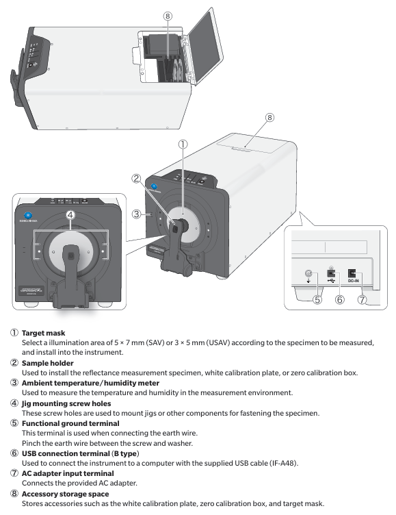
① Select a 5 × 7mm (SAV) or 3 × 5mm (USAV) illumination area for the target mask based on the sample to be measured, and install it on the device
② The sample rack is used to install reflectance measurement samples, white calibration plates, or zero calibration boxes
③ Environmental temperature and humidity meter measures the temperature and humidity of the environment
④ Fixture installation screw holes are used to install fixtures or other components to secure samples
⑤ When connecting the functional grounding terminal to the grounding wire, clamp the grounding wire between the screw and washer
⑥ USB connection terminal (Type B) connects devices and computers through the standard USB cable (IF-A48)
⑦ AC adapter input terminal connection provided
⑧ Attachment storage space stores attachments such as white calibration board, zero calibration box, target mask, etc
(3) Indicator light
Operation keys and power keys
Power button (POWER): used to turn on/off the device power, press once to turn on, long press to turn off; When the power is turned on, the LED light above the key lights up in blue; When the LED light flashes, it indicates that the AC adapter cannot be unplugged during the power on/off process.
Measurement button: Blue light indicates that measurement can be performed; Orange light indicates incomplete calibration; Not lit indicates measurement or power off.
STATUS PANEL
Measurement mode indicator lights (SCI, SCE, REF, KREF.): The LED lights on indicate the measurement mode set through computer software. In the "SCI+SCE" mode, both the SCI and SCE lights are on simultaneously; REF represents reflectance measurement.
Measurement area indicator light (1X3): indicates the specifications of the measurement area.
Communication status indicator light (CONNECT): It lights up when the device is connected to the computer (connected to PC software).
Measurement process and operation steps
(1) Overview of Measurement Process
Refer to page number for step-by-step operation content
1. Connect the computer using a USB cable to connect the device to the computer 16
Connect the device to a power outlet using an AC adapter
3. Start the computer to open the connection (start the Windows system)-
4. Turn on the device power. 17. Turn on the device power
5. Start the SpectraMagic NX2 software and enable the control function-
6 Installation of calibration target mask Installation of calibration target mask (CM-A310/SAV) 18
7. Install the zero calibration box and perform zero calibration 20
8. Install the white calibration board and perform white calibration (when using the WAA function, perform it after white calibration, which takes about 20 seconds) 21
9 Installation of measurement target mask Installation of suitable measurement target mask 18
10. Set the sample and place it into device 22
11. Perform measurements using SpectraMagic NX2 software, or set the trigger measurement mode and press the measurement button on the device status panel to perform measurements-
After completing the measurement, turn off the device power, exit SpectraMagic NX2 software, and turn off the computer power
(2) Specific operational steps
Connecting Computers
In general, USB cables can be plugged and unplugged when the device is turned on, but it is recommended to connect them when the device is turned off: first turn off the device power, connect the B-type connector of the USB cable to the USB terminal of the device (make sure it is fully inserted and firmly connected), then connect the A-type connector to the USB port of the computer, and then connect the AC adapter and turn on the device power; If prompted to install a USB driver, you need to specify the USB driver that comes with the software that can connect and operate the device to complete the installation. After installation, you need to turn off the power and then turn it back on.
Attention: The USB communication of the device complies with the USB 2.0 standard; The device cannot be powered through a USB cable and needs to be connected to an AC adapter before use; When connecting/disconnecting USB cables, hold the connector tightly and do not pull or forcefully bend the cable to avoid cable breakage; Ensure that the cable length is sufficient to avoid connection failure or cable breakage caused by tension.
Connect the communication adapter
First, confirm that both the device and computer power are turned off (LED lights are not on). Connect the DC output plug of the AC adapter to the DC input terminal on the side of the device, and then connect the power plug of the AC adapter to a 100V (50/60Hz) AC socket; Note that the AC adapter (AC-A312F) that comes with the device must be used, and the plug must be fully inserted. Before plugging in or unplugging the DC output plug, make sure the power switch is turned off.
Turn on/off the power
Power on: When the power is turned off, press and hold the power button for about 1 second to turn on the power, and the LED light above the power button will turn blue; Note that when the power button is pressed, the LED light flashes to indicate that the AC adapter cannot be unplugged during the power on process.
Shutdown: Press and hold the power switch for about 3 seconds to turn off the power. The LED light will flash and then turn off; Similarly, the flashing LED light indicates that the AC adapter cannot be unplugged during the shutdown process.
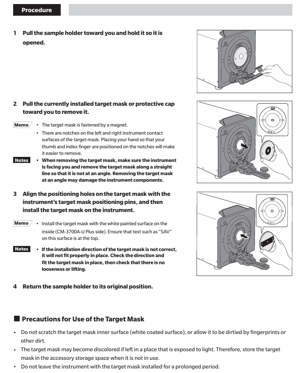
Install target mask
First, pull out the sample rack in your own direction and keep it open. Then, pull out and remove the currently installed target mask or protective cover in your direction (the target mask is fixed by a magnet, and there are grooves on both sides of its contact surface with the device. Place your thumb and index finger in the grooves for easy removal; make sure the device is facing you when removing it, and remove it in a straight line to avoid tilting and damaging device components).
Then align the positioning holes of the target mask with the positioning pins of the device's target mask, and install the target mask onto the device (ensuring that the white coating surface on the inside of the target mask faces the device (CM-3700A-U Plus side), and that the text such as "SAV" on the surface faces up). Finally, restore the sample rack to its original position.
Attention: When performing zero calibration or white calibration, the target mask CM-A310 (SAV) must be used; If the target mask is installed in the wrong direction, it will not be installed correctly. It is necessary to check the direction and install it to ensure that there is no looseness or warping; Do not scratch the inner surface of the target mask (white coating surface) to avoid fingerprints or other dirt; The target mask may change color when exposed to light, and should be stored in the attachment storage space when not in use; Do not let the device have the target mask installed for a long time.
Mask detection function
Use the optional software (SpectraMagic NX2) to enable mask detection, install the target mask (refer to the "Installing Target Mask" steps), and then check if the indicator light matches the size of the installed mask; If the size does not match, it is necessary to check whether the target mask is installed correctly (if not installed correctly, reinstall), whether there is dirt or scratches on the installation surface of the target mask (if there is, use a dust blower to remove the dust and dirt, do not touch the white coating surface of the target mask or wipe it with a cloth. If the dirt on the non white coating surface is difficult to remove, use a soft cloth dipped in ethanol to wipe it). If the problem is still not solved, contact an authorized service organization.
Attention: Detection errors may occur when the target mask is not installed correctly or is dirty or scratched.
White calibration data
The white calibration data of the white calibration board is provided under the following measurement conditions: SAV (measurement area 1 × 3mm, illumination area 5 × 7mm)/specular reflection component: SCI; SAV (measurement area 1 × 3mm, illumination area 5 × 7mm)/specular reflection component: SCE.
Install zero calibration box
First, install the target mask (SAV) for calibration in advance, and use software to set the same specular reflection component (SCI/SCE) and ultraviolet output as during measurement (when strict precision fluorescence measurement is not required (fluorescence calibration is not performed), the ultraviolet cut-off filter does not cover the xenon lamp, and the ultraviolet output is set to 99.9).
Then pull out the sample holder in your own direction and keep it open (the sample holder will remain open after being opened about 70 degrees), insert the protruding part on the zero calibration box into the groove on the device, and fix the zero calibration box with the sample holder; After installation, it is necessary to check whether the zero calibration box is loose or warped.
Attention: Do not apply external force after installing the zero calibration box to prevent it from falling off; Avoid scratching the interior of the zero calibration box or getting fingerprints or other dirt on it; When the interior of the zero calibration box is dirty, gently wipe it with a soft, clean dry cloth. For dirt that is difficult to remove, wipe it with a cloth dipped in ethanol; When internal scratches or dirt cannot be removed, the zero calibration box needs to be replaced.
Install white calibration board
Install the target mask (SAV) for calibration in advance, and set the same specular reflection component (SCI/SCE) as during measurement through software (when strict precision fluorescence measurement is not required (fluorescence calibration is not performed), the UV cut-off filter does not cover the xenon lamp, and the UV output is set to 99.9).
Pull out the sample holder in your own direction and keep it open. Press the sample holder into the groove on the back of the white calibration plate as shown in the diagram to complete the installation.
Attention: If the set calibration start time (8 hours) has been exceeded since the last white calibration, "white calibration required" will be displayed when the device is turned on. Calibration must be performed before using the device; When using the WAA (Wavelength Analysis and Adjustment) function, it needs to be executed after white calibration, which takes about 20 seconds. After confirming the completion of WAA according to the progress bar displayed in the software, the white calibration board can be removed; The white calibration data has been set in the device at the time of purchase for white calibration; The white calibration board may discolor when exposed to light, so it should be covered when not in use to avoid exposure to external light; Avoid scratching or getting fingerprints or other dirt on the white calibration board; When the white calibration board is dirty, gently wipe it with a soft, clean dry cloth. For dirt that is difficult to remove, use a cloth dipped in ethanol to wipe it off. Then use a cloth dipped in water to wipe off the ethanol and dry it before use; When the white calibration board is scratched or the dirt cannot be removed, it needs to be replaced. After replacement, the data of the new white calibration board should be set as white calibration data.
Set up samples (reflectivity measurement)
When measuring the reflectivity of thin film or sheet samples, first install the sample into the sample holder, and then install the sample holder onto the equipment; When measuring samples that cannot be installed in the sample holder, remove the sample holder and make the sample measuring port in close contact with the sample for measurement.
Attention: The maximum thickness of the sample installed on the sample rack is 30mm.
reflectance measurement
Install the target mask for measurement in advance, and set the measurement area, specular reflection components, and ultraviolet output in advance through software.
Pull out the sample rack in its own direction and keep it open, put the sample in the sample rack, adjust the sample position so that the part to be measured is within the measuring point (when moving the sample position, pull out the sample rack in its own direction and keep it open to protect the sample surface), and then use the optional SpectraMagic NX2 color data software to perform the measurement; If the trigger measurement mode is selected, the measurement can also be performed through the measurement button on the device status panel.
Attention: To check the measurement point, the device can be connected to a computer and the viewfinder function of SpectraMagic NX2 software can be used. The viewfinder has a pointer indicating the measurement point. If the pointer color is close to the sample color and difficult to see, it can be switched to an analog pointer.
Opacity measurement
When using the optional SpectraMagic NX2 color data software, calculate opacity based on two measurement results: white background and black background.
- OMRON
- ABB
- General Electric
- EMERSON
- Honeywell
- HIMA
- ALSTOM
- Rolls-Royce
- MOTOROLA
- Rockwell
- Siemens
- Woodward
- YOKOGAWA
- FOXBORO
- KOLLMORGEN
- MOOG
- KB
- YAMAHA
- BENDER
- TEKTRONIX
- Westinghouse
- AMAT
- AB
- XYCOM
- Yaskawa
- B&R
- Schneider
- KONGSBERG
- NI
- WATLOW
- ProSoft
- SEW
- ADVANCED
- Reliance
- TRICONEX
- METSO
- MAN
- Advantest
- STUDER
- DANAHER MOTION
- Bently
- Galil
- EATON
- MOLEX
- DEIF
- B&W
- ZYGO
- Aerotech
- DANFOSS
- Beijer
- Moxa
- Rexroth
- Johnson
- WAGO
- TOSHIBA
- BMCM
- SMC
- HITACHI
- HIRSCHMANN
- Application field
- XP POWER
- CTI
- TRICON
- STOBER
- Thinklogical
- Horner Automation
- Meggitt
- Fanuc
- Baldor
- SHINKAWA
- Other Brands
- UniOP
- KUKA
- Iba
- Beckhoff
-
 Basler DECS-200-2L Digital Excitation Control
 -
 Basler BE1-47N Voltage Phase Sequence Relay
 -
 Basler AEC63-7 Analog Excitation Controller 220-277V
 -
 Basler BE1-50/51B-107 Overcurrent Relay
 -
 Basler Electric BE1‑32R BE1‑E1P‑BON0F Protective Relay
 -
 Basler BE1-25 Solid State Time Overcurrent Relay M1EA6PA5S1F
 -
 Basler MVC 232 Manual Voltage Control Module 90 37000 103 60VAC 55VDC
 -
 Basler RAL6144-16GM Racer GigE Line Scan Camera
 -
 Basler SSR 63-12 Static Voltage Regulator
 -
 Basler BE1-51A Overcurrent Relay
 -
 Basler BE1-87T Solid State Protective Relay
 -
 Basler SR4A2B01B3A Static Voltage Regulator
 -
 Basler SSR 32-12 Static Voltage Regulator
 -
 Basler TRR00696 Transformer 1KVA 115V
 -
 Basler DECS-100-B15 AVR Replacement
 -
Basler BE1-27 Under-Voltage Relay
-
 Basler ACA2000-50GM Interface Module
 -
 Basler AEC63-7 Analog Excitation Controller
 -
 Basler PRS 250 Veri-Sync Relay
 -
 Basler SR4A-2B15B3A Static Voltage Regulator
 -
Basler BE1-32R Power Relay
-
Basler SR8A-2B06B3E Static Voltage Regulator
-
Basler BE1-81 O/U Frequency Relay
-
 Basler BE1-51A-K2E-W6M-B1N0F Overcurrent Relay
 -
Basler BE1-851 Overcurrent Relay G3A1S1 – 48-125V AC/DC
-
 Basler BEI-51 Overcurrent Relay – NSN 5945-01-293-2363
 -
Basler Electric L301KC Protective Relay – L301KC
-
 Basler DECS-100-B15 Automatic Voltage Regulator – Generator AVR
 -
 Basler SR4A-2B15B3A Static Voltage Regulator – SR4A2B15B3A
 -
 Basler UF 312 Under Frequency Protective Module – 9094700100
 -
Basler Electric MVC 232 Manual Control Module – 60VAC 55VDC 20A
-
Basler PRS 250 Veri-Sync Relay – Generator Synchronizing Relay
-
 Basler DECS-100-A05 Digital Regulator Review
 -
 Basler AEM-2020 Analog Expansion Module Specs
 -
 Basler DECS-100-B15 Digital Excitation Specs
 -
Basler Electric 9125600106 Regulator Component
-
Basler BE1-51A-K1E-W6M-B1N0F Overcurrent Relay
-
 Basler MVC-301 MVC 300 Excitation Controller
 -
 Basler SSR 32-12 Static Voltage Regulator
 -
 Basler 9-2849-00-101 Control Module
 -
Basler BE1-51A Overcurrent Relay
-
 Basler BE1-51/27R Overcurrent Relay
 -
 Basler BE1-51 Overcurrent Relay
 -
 Basler SR8A-2B15B3A Static Voltage Regulator
 -
 Basler BE32965001 Transformer and Timer Board
 -
 Basler 9174700100 EL200-7 Excitation Limiter
 -
 Basler BE2000E AVR Voltage Regulator
 -
Basler BE1-87G Differential Relay
-
 Basler BE21834001 Generator Control Module
 -
Basler DECS-100-B15 AVR
-
 Basler D90 96801 100 PCB Card
 -
 Basler XR2002F Voltage Regulator (110 VAC, 48-480 Hz)
 -
 Basler SR8A-2B14B3A Regulator
 -
 Basler 9561500100 Module
 -
 Basler DECS-400 BE1-11 System
 -
 Basler DECS-100-B15 Excitation Control
 -
 Basler SCP 210 Frequency Controller
 -
Basler SR4A-2B15B3A Static Voltage Regulator
-
Basler BE1-32R Power Relay
-
 Basler PIA2400-17GM Power Interface Adapter
 -
 Basler MVC 232 Manual Voltage Control Module
 -
 Basler SSR 32-12 Static Voltage Regulator
 -
Basler 5MW AVR Generator Voltage Regulator
-
 Basler VR63-4B Voltage Regulator
 -
Basler DECS-100-A05 AVR for Engine Generator
-
Basler DECS-100-B15 Automatic Voltage Regulator
-
Basler BE1-32R Directional Power Relay
-
Basler BE1-87B Differential Relay
-
 Basler UFOV 260A Protective Module
 -
 Basler 9-2614-02-100 PCB Rev M
 -
Basler DECS-100-B15 Digital AVR
-
 Basler 9284900103 PS DECS-400N
 -
 Basler D4N3H1U Intertie Protection
 -
 Basler DECS-100-B15 A15 AVR
 -
 Basler KR4F Voltage Regulator
 -
 Basler BE26434 T14 Transformer
 -
 Basler SR8A-2B15B3A Regulator
 -
 Westinghouse 774B472A12 AR Relay
 -
Basler DECS-100-B15 AVR
-
Basler XR2002F Regulator 110V
-
Basler SR125-E Static Regulator
-
Basler SSR 125-12 Regulator
-
Basler MOC2599 Motor Pot
-
 Basler BE1-DFPR Feeder Relay
 -
 Basler CBS 305 Current Boost
 -
Basler BE1-25 AutoSync
-
Basler MVC 300 Voltage Control
-
 Basler BE3-25A AutoSync
 -
 Basler KR7FF Static Regulator
 -
Basler 90-49000-100 Regulator
-
 Basler 880 kVA Dry Type Transformer Specs
 -
Basler Electric BE1-25 Sync-Check Relay Specs
-
 Basler SSR 125-12 Voltage Regulator Specs
 -
 Basler Electric BE1-851 Overcurrent Relay Review
 -
Basler Electric 149D930G02 Control Sub-Assembly
-
 Basler Electric BE1-81O/UT Frequency Relay Specs
 -
 Basler Electric BE1-51/27C Overcurrent Relay
 -
 Basler Electric 149D956G02 Industrial Component
 -
Basler Electric BE1-51A Overcurrent Relay Specs
-
 Basler Electric BE1-40Q Loss of Excitation Relay
 -
Basler DECS-200 Excitation Control System
-
 Basler DECS-200 Voltage Regulator 56-277V AC / 125V DC
 -
Basler BE1-87T Transformer Differential Relay
-
 Basler RDP-110-S1 Protection Relay
 -
 Basler BE1-700V Digital Protective Relay
 -
 Basler BE1-951 Overcurrent Protection System
 -
 Basler DECS-300 Digital Excitation Control
 -
 Basler DECS-200 Digital Excitation Control
 -
 Basler DECS-200-1C Excitation Control System
 -
Basler DECS-200-1L Digital Excitation Control
-
 Basler Electric BE1-GPS Generator Protection System
 -
Basler Electric DECS-200-1C Digital Excitation Controller
-
 Basler Electric DECS125-15 Excitation Control with Power Module
 -
Basler Electric BE1-87G Differential Relay
-
 Basler Electric BE1-11 Protection System I5A3M2P2N0EA00
 -
Basler Electric DECS-200-1C Excitation Control System
-
Basler Electric BE1-11g Generator Protection Relay
-
Basler Electric DECS 125-15-B2C1 V2.0.9 Excitation Control
-
Basler Electric BE1-81O/UT3ED1JA7N2F Frequency Relay
-
Basler Electric BE1-81O/UT3EE1YB7N1F Frequency Relay
-
 Basler Electric DECS-200-1L Digital Excitation Control System
 -
Basler DECS125-15-B2C1 Excitation Control
-
 Basler 9507900205 SSR Retrofit Voltage Regulator
 -
 Basler BE2000E Digital Voltage Regulator
 -
 Basler BE1-GPS Generator Protection System
 -
Basler DECS-250-CN1CN1N Digital Excitation Control
-
 Basler DGC-2020 Genset Controller
 -
Basler BE1-81O UT3ED1LA7N0F Frequency Relay (Variant)


