
HIMA CPU 01 Controller Module
Storage and Execution: Stores the operating system (OS) and user programs, performs core functions such as logical operations, I/O signal processing, and security self checks.
Communication management: Implement secure/non secure communication with programming and debugging tools (PADT), remote I/O, and external systems through Ethernet and fieldbus interfaces.
Status monitoring: Real time monitoring of power supply voltage, operating temperature, hardware faults, and automatic triggering of safety response in case of abnormalities (such as entering STOP state).
Installation and configuration process
1. Installation steps
(1) Basic installation (inside the rack)
In the power-off state, insert the module along the upper and lower rails of the rack, align it with the backplane slot, and press the front end board until the buckle "clicks" to lock.
Secure the module with screws on both sides of the front panel to ensure a secure installation.
Connection cables: Ethernet cable (RJ-45), fieldbus cable (D-sub, requiring sub module connection), power cord (powered by power module, no direct wiring required).
(2) Zone 2 Special Installation
Additional requirements: The enclosure protection level should be ≥ IP54 to ensure heat dissipation (the basic power consumption of the module is 6.5W, and it can reach 12W when equipped with a communication submodule).
Power requirements: PELV/SILV grade safety isolation power supply must be used, in compliance with IEC 61131-2 standard.
Label pasting: The shell needs to be pasted with ATEX compliant labels, and the module comes with an "Ex113GExnA II T4X" label.
2. Configuration process
(1) Tool selection and preliminary preparation
Confirm module OS version: Select the corresponding programming tool (ELOP II Factory/SILworX) based on the model label or front-end LED.
Reference documents: HIMatrix system manual (HI 800 191 E), safety manual (HI 800 023 E), and programming tool help documentation are required.
(2) Core configuration steps
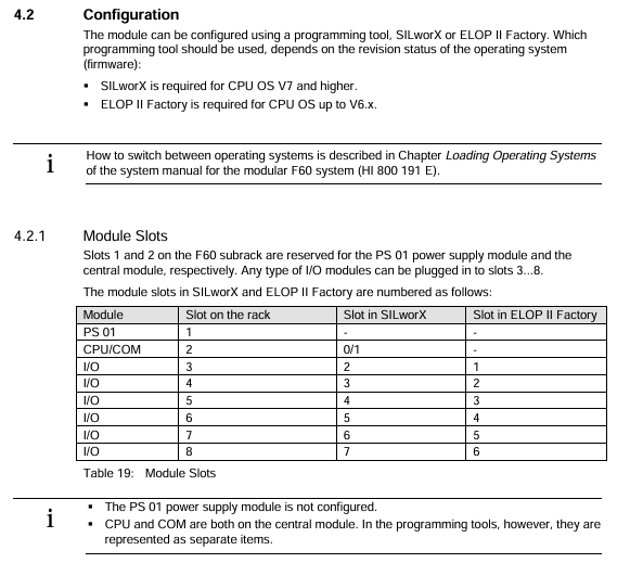
Hardware Mapping: Create a project in the programming tool and configure the CPU module (Slot 2) and I/O module (Slot 3~8) according to the rack slot. There is a slight difference in slot numbers between SILworX and ELOP II Factory (refer to the table below). |Rack slot | SILworX slot number | ELOP II Factory slot number | Module type | | --- | --- | --- | --- | | | | | | 1 | - | PS 01 power module (no configuration required) | | 2 | 0 (CPU)/1 (COM) | - | CPU/communication module (integrated) | | | 3 | 2 | 1 | I/O module | | 4 | 3 | 2 | I/O module | | | 5~8 | 4~7 | 3~6 | I/O module|
Network configuration: Set the IP address (default 192.168.0.99) and subnet mask to ensure consistency with the PADT (programming computer) network segment; If modifications are required, they can be restored to default values through programming tools or reset functions.
Programming and downloading: Write user programs using IEC 61131-3 standard languages such as Function Block Diagram (FBD), compile them, and download them to the module Flash EPROM.
Security configuration: Set the watchdog time (WDT) and security cycle time according to the security manual, and configure security communication parameters (if applicable).
3. Reset operation (restore default settings)
Applicable scenario: Forgetting administrator account password or IP address conflicts with PADT.
Operation steps:
Disconnect the module power supply and unplug all fieldbus connectors (to avoid interfering with other devices).
Insert a needle shaped insulating material into the reset hole of the front end board, press and hold for ≥ 20 seconds, and at the same time, turn on the power to restart the module.
Reset effect: The IP address is restored to 192.168.0.99, the system ID (SRS) is restored to 6000.0.0, and only the default administrator account (empty password) is activated.
Note: In COM OS versions ≥ 10.42, after resetting, it is necessary to reconfigure the connection parameters and account before downloading the program/OS.
Operation and Diagnosis
1. Running status indication (LED interpretation)
The LED status of the module varies slightly with the CPU OS version, and its core meaning is as follows:
(1) System LED
Meaning of LED color status (CPU OS ≥ V8)
RUN green constantly on and running normally (STOP/RUN status)
RUN green Blinking1 (600ms on/off) is loading a new operating system
RUN green off, non RUN state
ERR red constant light lacks additional function authorization and testing mode
ERR red Blinking1 fault shutdown (hardware/voltage/configuration failure), requiring PADT restart
ERR red goes out without any malfunction
(2) Program LED
STOP (red): Always on=STOP/valid configuration; Blinking=STOP/Invalid configuration.
PROG (yellow): Always on=loading configuration/OS, modifying WDT/safe time/SRS.
Fault (yellow): Blinking=OS damage, invalid configuration, I/O failure.
FORCE (yellow): constantly on=forced function preparation; Flashing=forced function activation.
(3) Communication LED
Ethernet (next to RJ-45): Green=Full Duplex; Yellow=connection is valid; Flashing=data transmission/conflict.
Fieldbus (FB1/FB2): yellow=interface activated; Synchronized flashing=emergency loader activated.
2. Basic operating procedures
(1) Start the process
Confirm that the module is securely installed, the cable connections are correct, and there is no risk of static electricity.
Connect the power module to supply power, and the module will automatically perform LED self-test (all LEDs will briefly light up).
Start the programming tool and establish a communication connection with the module (via IP address).
Download user programs and configuration files to verify the validity of the configuration.
Switch the module to RUN state and confirm normal operation through LED and programming tools.
- OMRON
- ABB
- General Electric
- EMERSON
- Honeywell
- HIMA
- ALSTOM
- Rolls-Royce
- MOTOROLA
- Rockwell
- Siemens
- Woodward
- YOKOGAWA
- FOXBORO
- KOLLMORGEN
- MOOG
- KB
- YAMAHA
- BENDER
- TEKTRONIX
- Westinghouse
- AMAT
- AB
- XYCOM
- Yaskawa
- B&R
- Schneider
- KONGSBERG
- NI
- WATLOW
- ProSoft
- SEW
- ADVANCED
- Reliance
- TRICONEX
- METSO
- MAN
- Advantest
- STUDER
- DANAHER MOTION
- Bently
- Galil
- EATON
- MOLEX
- DEIF
- B&W
- ZYGO
- Aerotech
- DANFOSS
- Beijer
- Moxa
- Rexroth
- Johnson
- WAGO
- TOSHIBA
- BMCM
- SMC
- HITACHI
- HIRSCHMANN
- Application field
- XP POWER
- CTI
- TRICON
- STOBER
- Thinklogical
- Horner Automation
- Meggitt
- Fanuc
- Baldor
- SHINKAWA
- Other Brands
- UniOP
- KUKA
- Iba
- Beckhoff
-
 Basler D90 96801 100 PCB Card
 -
 Basler XR2002F Voltage Regulator (110 VAC, 48-480 Hz)
 -
 Basler SR8A-2B14B3A Regulator
 -
 Basler 9561500100 Module
 -
 Basler DECS-400 BE1-11 System
 -
 Basler DECS-100-B15 Excitation Control
 -
 Basler SCP 210 Frequency Controller
 -
 Basler SR4A-2B15B3A Static Voltage Regulator
 -
 Basler BE1-32R Power Relay
 -
 Basler PIA2400-17GM Power Interface Adapter
 -
 Basler MVC 232 Manual Voltage Control Module
 -
 Basler SSR 32-12 Static Voltage Regulator
 -
 Basler 5MW AVR Generator Voltage Regulator
 -
 Basler VR63-4B Voltage Regulator
 -
 Basler DECS-100-A05 AVR for Engine Generator
 -
 Basler DECS-100-B15 Automatic Voltage Regulator
 -
 Basler BE1-32R Directional Power Relay
 -
 Basler BE1-87B Differential Relay
 -
 Basler UFOV 260A Protective Module
 -
 Basler 9-2614-02-100 PCB Rev M
 -
Basler DECS-100-B15 Digital AVR
-
 Basler 9284900103 PS DECS-400N
 -
 Basler D4N3H1U Intertie Protection
 -
 Basler DECS-100-B15 A15 AVR
 -
 Basler KR4F Voltage Regulator
 -
 Basler BE26434 T14 Transformer
 -
 Basler SR8A-2B15B3A Regulator
 -
 Westinghouse 774B472A12 AR Relay
 -
Basler DECS-100-B15 AVR
-
Basler XR2002F Regulator 110V
-
Basler SR125-E Static Regulator
-
 Basler SSR 125-12 Regulator
 -
 Basler MOC2599 Motor Pot
 -
 Basler BE1-DFPR Feeder Relay
 -
 Basler CBS 305 Current Boost
 -
 Basler BE1-25 AutoSync
 -
 Basler MVC 300 Voltage Control
 -
 Basler BE3-25A AutoSync
 -
 Basler KR7FF Static Regulator
 -
 Basler 90-49000-100 Regulator
 -
 Basler 880 kVA Dry Type Transformer Specs
 -
 Basler Electric BE1-25 Sync-Check Relay Specs
 -
 Basler SSR 125-12 Voltage Regulator Specs
 -
 Basler Electric BE1-851 Overcurrent Relay Review
 -
Basler Electric 149D930G02 Control Sub-Assembly
-
 Basler Electric BE1-81O/UT Frequency Relay Specs
 -
 Basler Electric BE1-51/27C Overcurrent Relay
 -
 Basler Electric 149D956G02 Industrial Component
 -
Basler Electric BE1-51A Overcurrent Relay Specs
-
 Basler Electric BE1-40Q Loss of Excitation Relay
 -
 Basler DECS-200 Excitation Control System
 -
 Basler DECS-200 Voltage Regulator 56-277V AC / 125V DC
 -
Basler BE1-87T Transformer Differential Relay
-
 Basler RDP-110-S1 Protection Relay
 -
 Basler BE1-700V Digital Protective Relay
 -
 Basler BE1-951 Overcurrent Protection System
 -
 Basler DECS-300 Digital Excitation Control
 -
 Basler DECS-200 Digital Excitation Control
 -
 Basler DECS-200-1C Excitation Control System
 -
Basler DECS-200-1L Digital Excitation Control
-
 Basler Electric BE1-GPS Generator Protection System
 -
Basler Electric DECS-200-1C Digital Excitation Controller
-
 Basler Electric DECS125-15 Excitation Control with Power Module
 -
 Basler Electric BE1-87G Differential Relay
 -
 Basler Electric BE1-11 Protection System I5A3M2P2N0EA00
 -
Basler Electric DECS-200-1C Excitation Control System
-
Basler Electric BE1-11g Generator Protection Relay
-
Basler Electric DECS 125-15-B2C1 V2.0.9 Excitation Control
-
 Basler Electric BE1-81O/UT3ED1JA7N2F Frequency Relay
 -
Basler Electric BE1-81O/UT3EE1YB7N1F Frequency Relay
-
 Basler Electric DECS-200-1L Digital Excitation Control System
 -
Basler DECS125-15-B2C1 Excitation Control
-
 Basler 9507900205 SSR Retrofit Voltage Regulator
 -
 Basler BE2000E Digital Voltage Regulator
 -
 Basler BE1-GPS Generator Protection System
 -
Basler DECS-250-CN1CN1N Digital Excitation Control
-
 Basler DGC-2020 Genset Controller
 -
 Basler BE1-81O UT3ED1LA7N0F Frequency Relay (Variant)
 -
 Basler BE1-81O UT3EE1YA9S0F Frequency Relay (Variant)
 -
Basler BE1-81O Over/Under Frequency Relay
-
Basler DECS125-15 Digital Excitation Control
-
Basler Electric BE1-951 Overcurrent Protection System
-
 Basler Electric BE1-700V Digital Protective Relay
 -
 Basler Electric APR63-5 Automatic Voltage Regulator
 -
Basler Electric BE1-851 Overcurrent Protection System
-
Basler Electric DECS-250-LN1SN1N Excitation Control
-
 Basler Electric BE1-87T Transformer Differential Relay
 -
Basler Electric DECS-200-1L Excitation Control System
-
 Basler Electric 9310300100 DECS-300 Excitation Control
 -
 Basler Electric SSE-N 125-4.5KW Shunt Exciter Regulator
 -
 Basler Electric DGC-2020HD-5NS1DNSBA Genset Controller
 -
Basler Electric BE1-81-O/UT3EE1JB7N1F Frequency Relay
-
Basler Electric BE1-81T1EE1WA0N1F Frequency Relay
-
 Basler Electric BE1-25M1EA6PN5R1F Sync-Check Relay
 -
 Basler Electric BE1-GPS Generator Protection System
 -
Basler Electric DECS-250-LN1SN1N Excitation Control Rev V
-
 Basler Electric DECS-250-CN2CN1N Excitation Control
 -
Basler Electric BE1-50/51B-207 Overcurrent Relay
-
Basler Electric DECS-300-C0N0 Excitation Control System
-
Basler Electric DECS-200 Digital Excitation Control System
-
Basler Electric DECS-250-LN1CN1N Excitation Unit
-
Basler Electric DECS-250 LN2SA1D Excitation Unit Specs
-
Basler Electric BE1-87T Transformer Relay Review
-
Basler Electric BE1-11 Protection System
-
Basler Electric BE1-GPS100-E4N1H1N Protection System
-
 Allen-Bradley 442G-MABH-R Safety Module
 -
 Beckhoff CX1030-0111 PLC Assembly Profile
 -
 FANUC IC693CPU364 PLC Module
 -
 Orange Denmark Type 200816 220 PLC Specs
 -
 OMRON C200H-SNT31 Sysmac PLC Module
 -
 Allen Bradley 20AB022A3AYNANC0 PowerFlex 70
 -
 OMRON C200HW-PCU01 Position Control Unit
 -
 ABB AO845A-eA Analog Output Module
 -
 OMRON CJ1M-CPU22 CPU Unit
 -
 Allen Bradley 100-E265ED11 Contactor
 -
 Honeywell 51304511-100 Interface Module
 -
 SOLEXY BXF3S0101N0018 Gateway Module
 -
 OMRON CJ2H-CPU65 CPU Unit
 -
 Automation Direct GS2-45P0 AC Drive
 -
 M68-2000 2-Axis Motion CNC Controller
 -
 OMRON CJ1M-CPU11 V3.0 PLC CPU Unit
 -
 OMRON CJ1W-NC413 4-Axis Positioning Controller
 -
 OMRON 3G2A3-PRO16 Programming Console HMI
 -
 Siemens 3VT8440-2AA04-2GA2 Molded Case Circuit Breaker
 -
 Siemens 3RT5045 Contactor Series
 -
 OMRON C200HS-CPU01-E SYSMAC PLC Controller
 -
 OMRON C500-NC103-E Positioning Control Unit
 -
 OMRON CJ1W-TC001 Temperature Control Unit


