
Woodward DSLC Digital Synchronizer and Load Controller: Installation, Operation, and Troubleshooting Guide
This article provides a detailed introduction to various aspects of the DSLC control system, from basic functions to installation specifications, from configuration adjustments to troubleshooting, providing a comprehensive reference guide for engineering and technical personnel. In practical applications, it is recommended to refer to this manual and relevant technical documents based on the specific system characteristics and operating environment to ensure the best performance and longest service life of the system.
Woodward DSLC Digital Synchronizer and Load Controller: Installation, Operation, and Troubleshooting Guide
In today's industrial and commercial power systems, synchronous grid connection and load control of generator sets are key links to ensure the stability and efficiency of power supply. Woodward Corporation's DSLC ™ As an advanced microprocessor control system, Digital Synchronizer and Load Control provides a complete synchronization, parallel connection, loading, and unloading solution for three-phase generator sets. This article will provide a comprehensive reference guide for engineers and technicians by delving into the technical characteristics, installation points, operating methods, and troubleshooting strategies of the system.
1、 Overview of DSLC Control System
1.1 Product Features and Application Scope
The DSLC control system is a generator load controller designed specifically for use with Woodward speed control and automatic voltage regulators. The system adopts digital signal processing technology, significantly improving synchronization accuracy and load measurement accuracy, and can maintain excellent performance even in the case of waveform distortion.
The main functions include:
Optional phase matching or slip frequency synchronization function, with voltage matching and automatic dead bus closure capability
Automatic generator loading and unloading, achieving undisturbed load transfer
Control capability for sag, base load, and isochronous load
Process control functions such as cogeneration, import and export control, pressure control, etc
Implement equal time load distribution with other units equipped with DSLC control
Reactive Power/Power Factor Control (Full Function Model)
Built in diagnostic function
Multi functional adjustable high and low limit alarm and load switch
Digital communication networks support load distribution, reactive power/power factor distribution
Complete setup, metering, and diagnostic functions are achieved through a handheld programmer
Reverse power relay protection
1.2 System composition and specifications
The DSLC control system can be divided into full function models and simplified function models based on their functions, with the latter not including reactive power/power factor control and process control functions. The system supports multiple wiring configurations, including 120V/240V star wiring and 120V/240V open delta wiring, to accommodate different switchgear configurations.
Electrical specifications:
Control power supply: 18-40 VDC, 18W, 1A maximum
Synchronizer input: 45-66 Hz, with different voltage ranges according to PT configuration
Voltage detection input: three-phase, 45-66 Hz, accuracy 0.1% of full range
Current input: 0-5A RMS, maximum 7A RMS, accuracy 0.1% of full scale
Discrete input: 18-40 VDC, 10mA typical value
Relay drive output: 18-40 VDC, 200mA surge current capability
Environmental specifications:
Working temperature: -40 to+70 ° C
Storage temperature: -55 to+105 ° C
Humidity: 95% at 38 ° C
Mechanical vibration: 2.5G, 24-2000Hz
Electromagnetic compatibility: Complies with ANSI/IEEE C37.90.2 standard
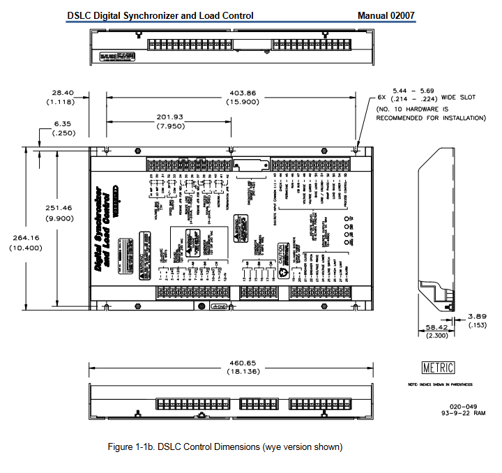
2、 Installation and wiring specifications
2.1 Installation location selection
When selecting the installation location for DSLC controllers, the following factors should be considered:
Avoid direct exposure to water or environments prone to condensation
Ensure that the working temperature is within the range of -40 to+70 ° C
Provide sufficient ventilation and cooling space to shield radiant heat sources
Stay away from high voltage and high current equipment
Reserve front maintenance space
Prevent objects from falling onto the terminal position
The chassis must be grounded to ensure safety and shielding
Do not install on the engine
2.2 Key points of electrical connection
Power connection:
Using an 18-40VDC low impedance power supply with a power of 18W
Negative terminal 1, positive terminal 2
Avoid sharing power cords with other devices
The length of the power cord should be as short as possible
Power on at least 15 seconds before expected use to ensure control completes power on diagnosis
Shielding wiring requirements:
All shielded cables must be twisted pair
Do not attempt to tin the braided shielding layer
The signal line should be shielded to prevent picking up stray signals from adjacent devices
The exposed wires outside the shielding layer should be as short as possible, not exceeding 50mm
The other end of the shielding layer must remain open and insulated from other conductors
The cable shielding layer should be connected to the chassis ground, with the input end only grounded at the control end and the output end grounded at the speed control and voltage regulator ends
2.3 Connection specifications for transformers
Voltage Transformer (PT) Connection:
The busbar and generator should use the same voltage transformer
Bus phase A must correspond to generator A connected to the load sensor
The phase sequence of the busbar must correspond to the phase sequence of the generator to ensure the normal operation of the synchronizer
Select the correct PT wiring method (star or open delta) based on the configuration of the switchgear
Current Transformer (CT) Connection:
The CT connection must be correct, and the corresponding phase CT and PT must be connected to the same phase terminal controlled by DSLC
It is necessary to observe the correct polarity
Provide 5A RMS full load current for optimal system performance
There is a risk of fatal electric shock if any wires connected to the generator CT terminal are disconnected while the engine is running
3、 System configuration and calibration
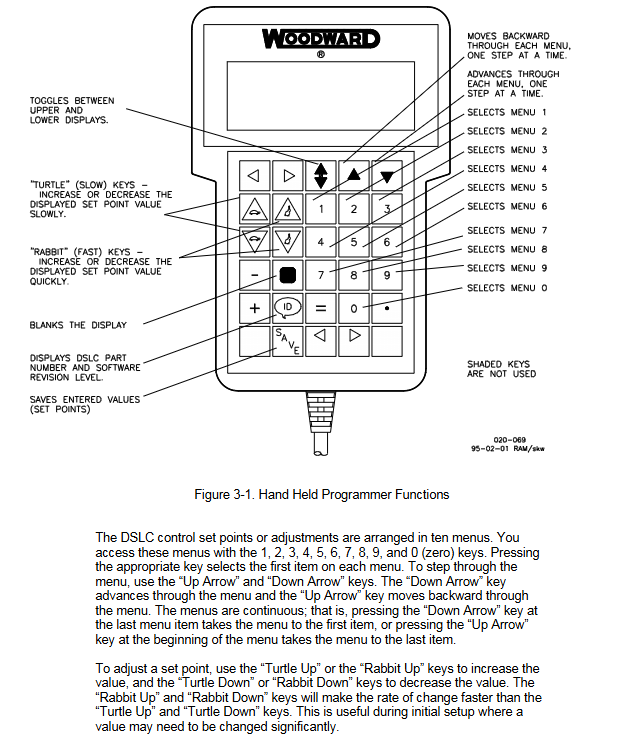
3.1 Use of Handheld Programmer
A handheld programmer is a small computer terminal that connects to the DSLC control RS-422 diagnostic and service port. Its main functions include:
After completing the power on self-test, press the ID key to display the control software part number and revision level
Four line backlit LCD display screen, capable of viewing two functions or menu items simultaneously
Access ten settings menus through numeric keys 1-0
Use the 'up/down arrow' keys to navigate through the menu
Use the "Turtle" key (slow) and the "Rabbit" key (fast) to adjust the set value
Press the 'Save' button to store the set values in the EEPROM memory
3.2 Detailed explanation of menu system
Menu 1- Synchronizer Settings:
Contains 16 parameters including synchronization gain, stability, slip frequency reference, voltage matching, and dead bus closure, used to optimize synchronization performance.
Menu 2- Load Control:
Contains 30 parameters including load control gain, stability, mode selection, rated load, base load, unloading trip, etc., used for precise control of generator load.
Menu 3- Process Control (Full Function Model):
Contains 16 parameters including process control gain, stability, dead zone, reference value, etc., used for process control applications.
Menu 4- Reactive Power/Power Factor Control (Full Function Model):
Contains 17 parameters including control mode, gain, stability, rated reactive power, reference value, etc., used for reactive power or power factor control.
Menu 5- Configuration:
Contains 9 parameters including PT winding ratio, CT rated value, PT voltage input, system frequency, etc., used for basic system configuration.
Menu 6- Calibration:
It includes 13 calibration items such as process input, remote input, speed bias output, and voltage bias output to ensure measurement accuracy.
Menu 7- Generator Electrical Parameters:
Provide 20 real-time monitoring parameters including active power, apparent power, reactive power, power factor, and voltage and current of each phase.
Menu 8- Control Status Monitor:
Display 13 status information including synchronizer mode, load control mode, load reference, process reference, etc.
Menu 9- Discrete Input/Output:
Display the status of all switch inputs and relay outputs, with a total of 25 monitoring points.
Menu 0- Diagnosis:
Provide 14 diagnostic information including diagnostic results, ROM checksum, number of active DSLCs, and network error statistics.
3.3 Initial setup program
Pre startup setup steps:
Connect the handheld programmer to provide power supply for DSLC control
Verify that the diagnostic result (menu 0) is 49, indicating that it has passed the self-test
Select menu 5, set the configuration key to 49, and configure basic parameters
Set all parameters of synchronizer menu 1 according to the worksheet
Set all parameters of load control menu 2 and initially use proportional load control mode
Set all parameters of process control menu 3 (if used)
Set all parameters of reactive power/power factor control menu 4 and initially disable this function
4、 Adjustment and optimization
4.1 Synchronizer Adjustment
Phase matching synchronizer settings:
Set the slip frequency reference to 0.0Hz and select phase matching
Turn off the synchronizer check mode switch
Adjust synchronous gain to achieve stable frequency control
Verify the performance of the synchronizer under different operating conditions
Slip frequency synchronizer setting:
Complete phase matching synchronizer setup
Set the required slip frequency reference value
Adjust synchronization gain and stability to achieve smooth phase rotation
Verify the performance of the synchronizer under various operating conditions
Voltage matching adjustment:
For voltage regulators using MOP: Adjust the voltage ramp time and verify the voltage matching function
For direct voltage bias input: adjust the voltage range potentiometer and set the desired voltage range
Set voltage high and low limits and alarm function
4.2 Load Control Adjustment
Proportional base load control setting:
Set the load control gain to 0.25
Carefully set the engine speed to achieve synchronous speed
Close the base load switch contactor, open the load/unload and process contactors
Select the synchronizer operation mode to connect the generator in parallel with the busbar
Verify load stability and control performance
Integral based load control setting:
Complete proportional load control settings
Set the load control mode to integral
Adjust load control gain, stability, and derivative parameters
Verify control stability under various load conditions
Timed load distribution adjustment:
Verify that the rated load setting is correct
Check that the number of DSLCs in the activity matches the number of installations
Set the load distribution gain to 0.72
Verify load distribution performance
4.3 Process Control Adjustment
Set process control gain, stability, derivative, dead zone, and filter parameters
Select direct or indirect control actions based on process characteristics
Set process reference values
Adjust dynamic parameters to achieve stable process control
Set process high and low limit values and alarm functions
4.4 Reactive Power/Power Factor Control Adjustment
Verify that voltage matching adjustment has been completed
Set reactive power/power factor gain and stability parameters
Set rated reactive power and reference value
Adjust and control dynamic parameters
Set power factor dead zone to reduce response to minor changes
Enable voltage fine-tuning function (if necessary)
5、 Network Communication and Remote Monitoring
5.1 LonWorks Network Configuration
The DSLC control system uses Echelon's LonWorks technology for inter device communication, supporting load distribution, reactive power/power factor distribution, and dead bus closure permission management.
Network specifications:
Data rate: 1.25 Mbps
Network isolation: 1000Vrms (60 seconds) at 60Hz, 277Vrms (continuous)
Common mode range: 277Vrms
Electrostatic discharge: 15kV
Maximum number of nodes per bus: 64 (0 to+70 ° C), 32 (-20 to+85 ° C), 20 (-40 to+85 ° C)
Network bus length: 500m (-20 to+85 ° C), 150m (-40 to+85 ° C)
Maximum stub length: 300mm (-40 to+85 ° C), 600mm (0 to+70 ° C)
Network terminal: Terminals need to be installed on both ends of the network
Wiring requirements:
Use the recommended shielded twisted pair cable
Ensure that the bus length is less than 500m
The length of the stub is less than 300mm
Less than 32 network devices
Minimize exposed wires outside the shielding layer
Verify the shielding continuity of the entire network
Grounding shielding layer at the center position
Install terminals only on both ends of the network
Avoid wiring together with power cords or other high electrical noise circuits
5.2 Remote monitoring function
The DSLC control system provides complete remote monitoring functions through the LonWorks network, including:
Electrical parameter output:
Real time data such as voltage, current, power, and power factor are provided through three data structures (ELEC-PARAOUT1, OUT2, OUT3) with an update rate of 1 second.
Remote control input:
Net_demote_in: Network remote load or process control reference input
Net_decess_in: Network input from LonWorks compatible process transmitters
Net_iscrete_in: Network input from remote sequencer
Discrete input/output states:
The status of all switch inputs and relay outputs can be monitored through the network.
6、 Troubleshooting and Maintenance
6.1 Common problem diagnosis
Unit unable to power on:
Check the+24V power supply
Ensure the correct polarity of the power supply
Check if the software PROM is installed correctly
Unstable load control:
Check phase current and voltage calibration
Adjust the rated speed of the speed control unit
Change the load control mode
Unstable process control mode:
Ensure that the load control is set to proportional control
Dynamically adjust the process control again
Unstable reactive power/power factor control mode:
Dynamically adjust reactive power/power factor control again
Remove cross current compensation from the voltage regulator circuit
Incorrect load allocation during waiting:
Check if the rated load setting is correct
Adjust the rated speed of the speed control unit
6.2 Network Troubleshooting
The number of DSLCs in the activity is incorrect:
Check if all DSLC controlled network addresses are unique
Verify whether the network cabling complies with specifications
Check the impact of each DSLC control on the network one by one
Network communication error:
Check if the network cabling installation complies with the specifications
Verify if the network is overloaded
Check if there are any equipment malfunctions affecting network communication
6.3 Service Options
Woodward offers a variety of product and service options:
OEM and packager support: Obtain services through original equipment manufacturers or device packagers
Woodward Business Partner Support: Obtain services through a global network of independent business partners
Factory repair options: including replacement/exchange, uniform rate repair, and uniform rate remanufacturing
Return to equipment maintenance:
Contact the full-service distributor in advance to obtain return authorization and shipping instructions
Attach a label containing complete information when transporting goods
Packaging control equipment according to specifications to prevent transportation damage
7、 Safety precautions
7.1 Warning and Notice
Important definition:
Danger: Indicates a dangerous situation that, if not avoided, may result in death or serious injury
Warning: Indicates a dangerous situation that, if not avoided, may result in death or serious injury
Attention: Indicates a dangerous situation, which may result in minor or moderate injury if not avoided
Notice: Indicates the potential danger of property damage
Important: Specify operation prompts or maintenance suggestions
Key safety requirements:
Engines, turbines, or other types of prime movers should be equipped with overspeed shutdown devices
The overspeed shutdown device must be completely independent of the prime mover control system
Prepare for emergency shutdown when starting the engine, turbine, or other prime mover
Always wear appropriate personal protective equipment
Turn off the charging device before disconnecting the battery to prevent damage to the control system
7.2 Prevention of Electrostatic Discharge
Static electricity prevention measures:
Discharge body static electricity before handling control equipment
Avoid using plastic, vinyl and foam around printed circuit boards
Do not touch the components or conductors on the printed circuit board with your hands or conductive devices
Wear cotton or cotton blend materials as much as possible to reduce static electricity accumulation
- OMRON
- ABB
- General Electric
- EMERSON
- Honeywell
- HIMA
- ALSTOM
- Rolls-Royce
- MOTOROLA
- Rockwell
- Siemens
- Woodward
- YOKOGAWA
- FOXBORO
- KOLLMORGEN
- MOOG
- KB
- YAMAHA
- BENDER
- TEKTRONIX
- Westinghouse
- AMAT
- AB
- XYCOM
- Yaskawa
- B&R
- Schneider
- KONGSBERG
- NI
- WATLOW
- ProSoft
- SEW
- ADVANCED
- Reliance
- TRICONEX
- METSO
- MAN
- Advantest
- STUDER
- DANAHER MOTION
- Bently
- Galil
- EATON
- MOLEX
- DEIF
- B&W
- ZYGO
- Aerotech
- DANFOSS
- Beijer
- Moxa
- Rexroth
- Johnson
- WAGO
- TOSHIBA
- BMCM
- SMC
- HITACHI
- HIRSCHMANN
- Application field
- XP POWER
- CTI
- TRICON
- STOBER
- Thinklogical
- Horner Automation
- Meggitt
- Fanuc
- Baldor
- SHINKAWA
- Other Brands
- UniOP
- KUKA
- Iba
- Beckhoff
- ADLINK
-
 Basler Electric BE1-700 Digital Protective Relay
 -
 Basler Electric SR8A-2B01B3A Static Voltage Regulator
 -
 Basler Electric SR4A-2B01B3E Static Voltage Regulator
 -
 Basler Electric 9017709102 PC Board
 -
Basler Electric SR4A-2B01B3A Static Voltage Regulator
-
 Basler Electric PRS-250 Veri-Sync Relay
 -
 Basler Electric 9066800102 Excitation Support System
 -
 Basler Electric BE1-87G Generator Differential Relay 9 1708 18 100
 -
 Basler Electric 36T865-2 BE03752001 Power Supply
 -
 Basler Electric M-300 149D940G02 Power Supply
 -
 Basler Electric ACA2040-25GM 4Mp 25Fps Area Scan Camera
 -
 Basler BE1-87G-S1A-A1C-A0N0 Differential Relay
 -
 Basler SR8A-2B06B3E Static Regulator SR8A2B06B3E
 -
 Basler SCP-210 Frequency Controller 9095400100
 -
 Basler BE1-59-A3E-A1J-N1N3F Overvoltage Relay BE159A3EA1JN1N3F
 -
 Basler 9 2011 11 100 Bracket Mounted Terminal Unit
 -
Basler 9 1606 00 101 Voltage Regulator
-
 Basler CBS-377 Current Boost System 9109600102
 -
 Basler 8650C72 Exciter Control Module PCB Rev 5
 -
 Basler C2EE1PA0N1F BE1-32R Reverse Power Relay
 -
 ADLINK HPCI-14S12U - Industrial Control Backplane 12PCI Backplane PCI-14S Passive Backplane
 -
-0010.png) ADLINK PCIe-GIE74C - image acquisition card 4-CH GigE Vision PoE+ Frame Grabber
ADLINK PCIe-GIE74C - image acquisition card 4-CH GigE Vision PoE+ Frame Grabber -
-0010_1.png) ADLINK PCI-8164 - control card 4-Axis Advanced Motion Controller Board
ADLINK PCI-8164 - control card 4-Axis Advanced Motion Controller Board -
 ADLINK PCIe-U304 - 4 Port USB3 PCIe Frame Grabbers USB Screw Hole Card
 -
 ADLINK PCI-9112 - Multi-Function Data Acquisition Card DAQ Card
 -
 ADLINK PCI-7432 - 51-12013-0A50 4-CH Isolated Numérique I/O PCI Cartes Digital I/O Card
 -
 ADLINK PCA-6106P3-0C1 REV.C1 - backplane 6-Slot Passive Backplane Board
 -
 ADLINK PCI-7224 - 24-CH Opto-Isolated Digital I/O PCI Board
 -
 ADLINK CPCI-7433R(G) - Digital Input Board Rear I/O CompactPCI Card
 -
 ADLINK EBP-13E4 - 51-46703-0A30 Industrial PC Backplane Passive Backplane
 -
 ADLINK PCIE-HDV62 - Image acquisition card High Definition Video Frame Grabber
 -
 ADLINK EBP-13E4 - 51-46703-0A30 Industrial Backplane Board Passive Backplane
 -
 ADLINK 90111-B1 / CPCI-6770 - PCB CPU MODULE CompactPCI Single Board Computer
 -
 ADLINK PCI-7248 - DATA ACQUISITION PCI CARD 48-CH Parallel Digital I/O Board
 -
 ADLINK PCI-7230 - 51-12003-0a50 board PCI7230 32-CH Isolated Digital I/O Card
 -
 ADLINK PCI2A000CB - 51-20000-0B30 Multi-Function DAQ Card Baseboard
 -
 ADLINK PCI-8134-005 - 4-Axis Motion Controller Card
 -
 ADLINK PCI-7224 - 24-CH Opto-Isolated Digital I/O PCI Card
 -
 ADLINK PCI-7434 - 64-CH Isolated Digital Output Card
 -
 ADLINK PCI-8132 - motion control card 2-Axis Servo & Stepper Controller
 -
 ADLINK PCI-8134 - Motion Controller PCI Card 4-Axis Controller Board
 -
 ADLINK PCI-8164 - Motion Control Card 51-12406-0A40 4-Axis Controller
 -
 ADLINK 51-12001-0C20 - Circuit Board Data Acquisition Interface Module Hardware
 -
 ADLINK NuPR0-840 - industrial control motherboard Full-Size PICMG CPU Board
 -
 ADLINK PCI-7444 - 51-12023-0A10 card 128-CH Isolated Digital Output Board
 -
 ADLINK PCI-1612B - data acquisition card 4-Port RS-232/422/485 Serial Communication Card
 -
 ADLINK PCI-6208V 009 - 8/16-CH 16-Bit Analog Output Cards PCB-I-E-482=6BX3
 -
 ADLINK NUPRO-935A/LV - industrial control motherboard Full-Size PICMG SBC Board
 -
 ADLINK PCI-9114DG - Multi-Function DAQ Card Data Acquisition PCI Card
 -
 ADLINK ACL-7130 - Data acquisition card Isolated Digital I/O Board
 -
 ADLINK ABX-6300D-4E1-BP - board ABX6300D4E1BP Video Interface Expansion Card
 -
 ADLINK CPCI-6940 - CPCI-6940/D1539/M16-0(EA)-000E 6U CompactPCI Processor Board
 -
 ADLINK NuPRO-760 - industrial control motherboard Half-Size PICMG SBC CPU Board
 -
 ADLINK IMB-M42H (G)-0020 - industrial control motherboard LGA1155 Micro-ATX Mainboard
 -
 ADLINK RTV-24 / PCI-MP4S - 51-12519-1C30 4-Channel Real Time Video Capture Board
 -
 ADLINK PCI-8134 - 4-Axis Servo & Stepper Motion Controller Card
 -
 ADLINK MXC-6101D - V.PC000.002.ST.00 Box PC Configurable Embedded Computer
 -
.png) ADLINK PCI-8134A - 51-12421-0A10 Motion Control Card 4-Axis Controller Card
ADLINK PCI-8134A - 51-12421-0A10 Motion Control Card 4-Axis Controller Card -
 ADLINK DIN-100S / DIN-100SA1 - Technology SCSI-II TB 100-PIN Terminal Block Board
 -
.png) ADLINK DIN-812M001 / DIN812M001 - 51-14034-0A1 51140340A1 Terminal Module Breakout Interface
ADLINK DIN-812M001 / DIN812M001 - 51-14034-0A1 51140340A1 Terminal Module Breakout Interface -
_1.png) ADLINK PCI-8164 - Servo motion control 4-Axis Advanced Controller Card
ADLINK PCI-8164 - Servo motion control 4-Axis Advanced Controller Card -
 ADLINK PCIe-GIE64 - Acquisition card GigE Vision PoE+ Frame Grabber
 -
 ADLINK M-302 - Industrial control motherboard ATX PC Board Mainboard
 -
 ADLINK PCI-8134 - Motion Controller PCI Card 4-Axis Controller Board
 -
 ADLINK PCI-RTV24 - Image capture card Analog Video Frame Grabber
 -
 ADLINK PCI-8102 - Motion control card 2-Axis Servo & Stepper Controller Board
 -
 ADLINK PCI-9112 REV.B1 - Card Multi-Function Data Acquisition Card
 -
 ADLINK HSI-DI32-M-N / HSL-TB32-M-DIN - Discrete I/O MODULE Distributed Automation Module System
 -
 ADLINK PCI-7296 - IO card REV.A3 96-CH Parallel Digital I/O Card
 -
-0020.png) ADLINK DIN-814P-A4 / 814Y - terminal board Motion Control Interface Block
ADLINK DIN-814P-A4 / 814Y - terminal board Motion Control Interface Block -
 ADLINK DIN-814P-A4 - 51-14056-0A10 PCB-I-E-2736=ZA01 Screw Terminal Board Breakout
 -
 ADLINK M-322 - motherboard Industrial Control Computer Mainboard
 -
 ADLINK NUPRO-406 REV:B1 - industrial control motherboard Full-Size PICMG CPU Board
 -
 ADLINK AMP-204C - card DSP-Based 4-Axis Advanced Pulse-Train Controller
 -
 ADLINK HPCI14S REV.B1 - industrial computer baseboard 14-Slot Passive Backplane
 -
 ADLINK PCI-7250 - 8-CH Relay Output & 8-CH Isolated DI PCI Card
 -
 ADLINK EBP-13E2 - baseplate Passive Backplane Industrial Computer Chassis Board
 -
 ADLINK LPCI-3488A - PCI-GPIB card 51-12801-0A30 acquisition card IEEE-488 Interface Board
 -
 ADLINK PCI-6216V-GL - 51-12201-0C30 16-CH 16-Bit Voltage Analog Output Card
 -
 ADLINK ACL-8454 - 16-CH Isolated Digital I/O & 4-CH Counter Card
 -
 ADLINK HPCI-9S7U - backplane Passive Backplane Compatible with NuPRO-A301 852 841 842
 -
 ADLINK DAQ-2010-007 - Simultaneous-Sampling Multi-Function Data Acquisition Card
 -
 ADLINK MP-C154 - 51-64205-0A10 Motion Control Card 4-Axis Controller Board
 -
 ADLINK MXE-202/mSSD16B/WiFi-BT - Matrix Rugged I/O Platform Embedded Fanless Computer
 -
 ADLINK CM-920-R-17 - PC/104-Plus Single Board Computer Module Intel Celeron M
 -
 ADLINK PCI-7250 NSMP - 8-CH Relay Output & 8-CH Isolated DI Card
 -
 ADLINK PCI-8164 - 4-Axis Motion Controller PCI Card W/ Cable and Breakout Box
 -
 ADLINK EMX-100 - Ethernet-based 4-axis Motion Controllers Distributed Motion Module
 -
.png) ADLINK PCI-8134A - Press control card 4-Axis Motion Controller Board
ADLINK PCI-8134A - Press control card 4-Axis Motion Controller Board -
 ADLINK M-845EG REV:3.2 - industrial motherboard Pentium 4 Socket 478 Micro-ATX
 -
 ADLINK PCI-9114A Rev A2 DG - card High-Resolution Multi-Function Data Acquisition Board
 -
 ADLINK IEC-915GV - REV 1.1 Industrial motherboard Socket 478 CPU Board
 -
 ADLINK PCI-9111DG(G) - Data Acquisition Card Multi-Function DAQ Card
 -
 ADLINK HPCI-15S10 REV:B2 - Industrial computer base plate Passive Backplane Board
 -
 ADLINK NuPR0-840 / NuPR0-840DV - industrial control motherboard Full-size PICMG CPU Board
 -
 ADLINK RTV-24 / PCI-MP4S - 51-12519-1C30 4-Channel Real Time Video Capture Board
 -
 ADLINK NUPRO-780 - industrial control motherboard Pentium III Single Board Computer
 -
 ADLINK PCI-7296 - 0050 card 96-CH Opto-Isolated Parallel DIO Card Set
 -
-0040.png) ADLINK NUPRO-780 - industrial control motherboard PICMG Full-Size SBC
ADLINK NUPRO-780 - industrial control motherboard PICMG Full-Size SBC -
 ADLINK PCI-7248 - 51-12006-0A3 002 Pci 7248 48-CH Parallel Digital I/O Card
 -
 ADLINK PCI-7230 - 32-CH Isolated Digital I/O Card
 -
 ADLINK AMP-204C - motion control card 4-Axis Advanced Controller Board
 -
.png) ADLINK PCI-1714UL - Card Ultra High-Speed 4-CH Simultaneous Sampling DAQ
ADLINK PCI-1714UL - Card Ultra High-Speed 4-CH Simultaneous Sampling DAQ -
 ADLINK NuPRO-E330 - industrial computer equipment motherboard PICMG 1.3 SHB SBC
 -
 ADLINK AMP-204C - DSP-Based 4-Axis Advanced Pulse-Train Motion Controller Module
 -
 ADLINK PCI-7256 - 001 51-12206-0A2 REV.A2 LPCI-7256 16-CH Latching Relay Output Card
 -
 ADLINK ND6050 - NUDAM DIGITAL I/0 MODULE Distributed I/O Unit
 -
 ASEM BM100 - Box PC Embedded Fanless Industrial Computer
 -
-3650.png) ADLINK PCI-7250 - PCI Acquisition Card 8-CH Relay Output & Isolated DI Board
ADLINK PCI-7250 - PCI Acquisition Card 8-CH Relay Output & Isolated DI Board -
 ADLINK PCI-8164 - Servo motion control 4-Axis Controller Card
 -
 Basler XR2002F Voltage Regulator 9139400101
 -
Basler 2D80367G23 DXCB De-Excitation Module 1200V 5000A
-
Basler SR4A-2B15B3A Static Regulator 120V 50/60Hz
-
 Basler SSR 125-12NF Static Regulator 9 1859 00 106
 -
 Basler BE1-BPR Breaker Protection Relay 9272000315
 -
 Basler SSR 63-12 Static Regulator 9 1859 00 101
 -
 Basler AEM-2020 Analog Expansion Module
 -
 Basler BE 25231-001 Transformer BE25231001
 -
Basler MVC 108 Manual Voltage Control 9037000102
-
 Basler PSS-100-Y5 Power System Stabilizer 0.1-5.0Hz
 -
Basler Electric BE1A-25-M1G-A6T-N4V1F Sync-Check Relay
-
 Basler Electric SR8A2B10B1A Static Voltage Regulator
 -
Basler Electric SR8A2B10B1A Static Voltage Regulator
-
Basler Electric SSR 125-12 Static Voltage Regulator 9185900102
-
 Basler Electric 90-73900-102 Power Supply (Westinghouse 2374A07G03)
 -
 Basler Electric 9400200117 Control Power Unit 12/24VDC 20W
 -
Basler Electric BE1-87G Solid State Generator Differential Relay
-
 Basler Electric BE1-32R Style C3ED1TA0S1F Solid State Protective Relay


