
TRICON ®/ Installation and maintenance of E/E2/E3 transmitters
TRICON ®/ Installation and maintenance of E/E2/E3 transmitters
Product Overview
core functionality
For Neptune ® The series of water meters provide electronic interfaces for water consumption monitoring and support various process controls based on water consumption, which can be integrated with SmartTrol ® Integrate controllers or third-party instrument devices to build complex measurement and monitoring systems.
Product Model and Classification
Divided by signal type
Digital Pulse
Basic model: 3-terminal design, outputting electrical pulses corresponding to water flow rate, requiring 12-24VDC power supply, suitable for scenarios that only require digital signals.
E2/E3 models: 5-terminal design, retaining basic features, new high-resolution output terminal and counting direction terminal, supporting high-speed bidirectional counter connection, also requiring 12-24VDC power supply, suitable for high-resolution digital signal demand scenarios.
Adaptation types: divided into two categories: Disc specific and Turbine specific, which can adapt to all Neptune disc or turbine watches.
Simulate 4-20mA type
5-terminal design, with digital pulse type basic functions, providing additional 4-20mA analog signal output proportional to water flow rate, requiring 24VDC power supply, suitable for scenarios that require both analog and digital signals.
Adaptation requirements: Strictly match the size and type of the water meter, confirm the compatible model when purchasing, and contact the manufacturer for technical support if necessary.
Special Model Description
The TRICON/E3 transmitter is not submersible and is not recommended for pit installation scenarios.
The T-8 disc gauge has been discontinued. Currently, all TRICON/E transmitters compatible with disc gauges are T-10 type. When compatible with T-8 gauges, it may not be possible to achieve a 20mA output level. The relevant values are only for calibration reference.
Key technical parameters
environmental conditions
Working temperature: 0 ° C~70 ° C (32 ° F~158 ° F)
Storage temperature: -40 ° C~85 ° C (-40 ° F~185 ° F)
Working humidity: 0~95% RH, no condensation
Electrical specifications (classified by model)
Pulse output (working temperature 0-70 ° C)
Low level output voltage (Vol): typical value 0.4V
High level output voltage (Voh): minimum value 8.5V, maximum value 12V, typical value is the power supply voltage minus 1.0V
Low level output current (Iol): typical value -10mA
High level output current (Ioh): typical value+10mA
Output rise time (tr l-h): maximum value 2 μ S (RL=2.4K Ω, CL=50pF)
Output decay time (tf h-l): maximum value 2 μ S (RL=2.4K Ω, CL=50pF)
4-20mA model (working temperature 0-50 ° C)
Power supply voltage (VCC): 22.5~26.5VDC
Power supply current (IS): 20~80mA
Loop resistance (RL): 0~600 Ω
Range accuracy (Gain): maximum 0.5% FS
Zero offset accuracy (Zero): maximum 0.2% FS
The digital pulse output parameters are consistent with the pulse output model
HF and UP/DN models (working temperature 0-70 ° C)
Power supply voltage (VCC): 11.5~26.5VDC
Power supply current (IS): 20~50mA
Low level output voltage (Vol): maximum value 0V
High level output voltage (Voh): typical value 24V, maximum value 26.5V
Low level output current (Iol): minimum value -1.0A
High level output current (Ioh): typical value 0.04A, maximum value 1.0W/Voh
Output rise/fall time: maximum value 2 μ S (RL=2.4K Ω, CL=50pF)
Absolute limit values for all models
Working temperature: 0~85 ° C
Storage temperature: -40~85 ° C
Power supply voltage: -30~30V
Pulse output load resistance: minimum 1200K Ω
Pulse output current: maximum 10mA
Note: Exceeding the above limit values may result in equipment damage
Performance data (classified by water meter type)
T-10 Disk Watch
Water meter size (inches) Maximum flow rate (gpm) Continuous maximum flow rate (gpm) Minimum flow rate (gpm) Number of pulses per gallon Maximum flow rate Pulse output (Hz) 4-20mA Output flow range (gpm)
⅝ 20 10 ¼ 578.10 192.70 0–20
¾ 30 15 ½ 322.60 161.30 0–30
1 50 25 ¾ 150.80 125.67 0–50
1½ 100 50 1½ 67.57 112.62 0–100
2 160 80 2 37.30 100.00 0–160
Note: The high-resolution output of TRICON/E2 requires multiplying the number of pulses per gallon and the maximum flow pulse output value by 36, and E3 requires multiplying by 40
T-8 Disc Watch (discontinued)
Water meter size (inches) Maximum flow rate (gpm) Continuous maximum flow rate (gpm) Minimum flow rate (gpm) Number of pulses per gallon Maximum flow rate Pulse output (Hz) 4-20mA Output flow range (gpm)
⅝ 20 10 ¼ 473.60 157.87 0–24.41
¾ 30 15 ½ 329.14 164.57 0–29.40
1 50 25 ¾ 126.55 105.46 0–59.58
1½ 100 50 1½ 47.86 79.77 0–141.18
2 160 80 2 25.60 68.27 0–234.37
Note: The high-resolution output coefficient is the same as the T-10 table; When the T-10 transmitter is adapted to the T-8 meter, the theoretical flow rate corresponding to the 20mA output is greater than the maximum allowable flow rate of the water meter, which cannot be achieved in actual operation
Trident ® Turbine gauge (TT)
Water meter size (inches) Continuous maximum flow rate (gpm) Minimum flow rate (gpm) Pulses per gallon Maximum flow rate Pulse output (Hz) 4-20mA Output flow range (gpm)
2 200 3 4.6080 15.36 0–200
3 450 5 2.8900 21.68 0–450
4 1000 10 1.5900 26.50 0–1000
6 2000 20 0.4640 15.47 0–2000
8(S/N≤31918014) 3500 35 0.2493 14.54 0–3500
8(S/N≥31918274) 3500 35 0.2253 13.14 0–3873
10(S/N≤31919282) 5500 50 0.1600 14.67 0–5500
10(S/N≥31919300) 5500 50 0.1472 13.49 0–5981
Note: E2 high-resolution output requires multiplying the number of pulses per gallon and the maximum flow pulse output value by 9, while E3 requires multiplying by 10
High Performance Turbine Meter (HPT)
Water meter size (inches) Continuous maximum flow rate (gpm) Minimum flow rate (gpm) Pulses per gallon Maximum flow rate Pulse output (Hz) 4-20mA Output flow range (gpm)
1½ 160 4 6.09500 16.25 0–160
2 200 4 6.09500 20.32 0–200
3 450 5 11.20000 84.00 0–450
4 1200 10 7.55600 151.1 0–1200
6 2500 20 0.72730 30.30 0–3000
8 4000 35 0.75560 50.37 0–4000
10 6500 50 0.75560 81.86 0–6500
12 8000 120 0.75560 100.75 0–8000
16 13500 200 0.07556 17.00 0–13500
20 22000 300 0.07556 27.71 0–22000
Note: The high-resolution output coefficient is the same as Trident's ® Turbine watch
Compound Meters
Core composition: Composed of a combination of turbine components and disk components, the components of different models of composite watches are matched differently (such as 3 "TRU/FLO consisting of 3" TT turbine components and ⅝ "T-10 disk components).
Performance reference: It is necessary to separately refer to the performance specifications of the corresponding turbine components and disc components. The 4 "/6"/8 "/10" HP TECTUS III turbine components have dedicated performance parameter tables.
Installation process
Pre-installation preparation
Tools and Materials
Essential tools: Medium sized flathead screwdriver, wire stripping pliers, hammer, ⅛ "diameter punch (or similar tools).
Essential material: # 22 AWG multi-core solid copper wire.
Optional material: Dow Corning ® # 4 moisture-proof compounds (or equivalent products).
Inspection and Storage
After unboxing, check whether the transmitter components (including the transmitter body, terminal cover, and installation ring) are intact, without damage or missing.
Before installation, the components need to be stored in a clean and dry environment, with a temperature maintained between -40 ° C and 85 ° C.
Safety and wiring specifications
Avoid placing instrument circuits near electrical noise sources such as contactors, motor starters, radio transmitters, and high-voltage power lines.
Separate the wiring of instrument circuits from other circuits and prioritize the use of independent metal conduits or metal cable trays; Long distance cabling (up to 1000 feet) requires # 22 AWG shielded twisted pair cables, with the shielding layer only grounded at the receiving device end.
When wiring needs to intersect, maintain a right angle intersection to reduce noise coupling; Use dedicated power sources (such as independent circuit breakers, isolation transformers) to ensure grounding in accordance with local electrical regulations.
Specific installation steps
1. Wiring operation
Unscrew the terminal cover screws, remove the terminal cover, thread the multi-core cable through the hole on the terminal cover, and move the terminal cover down along the cable to a convenient operating position.
Peel off the outer sheath of the cable by about 1.5 inches, separate the core wires and strip off the insulation layer of each core wire by about 0.5 inches. Use a screwdriver with a round handle to bend the bare copper wire into a hook shape.
Loosen the terminal screw of the transmitter, and wrap the hooks of each core wire clockwise around the corresponding terminal screw according to the wiring diagram (ensuring that the insulation layer is not pressed under the screw), and tighten the screw firmly (avoiding over tightening).
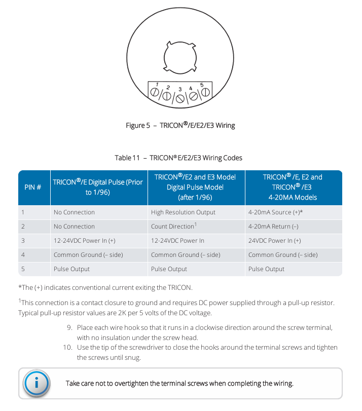
2. Wiring code (divided by pins)
Pin number TRICON ®/ E digital pulse type (before January 1996) TRICON ®/ E2/E3 digital pulse type (after January 1996) TRICON ®/ E/E2/E3 4-20mA type
1 connectionless high-resolution output 4-20mA source (+)
2 unconnected counting direction (ground contact closed, powered by pull-up resistor) 4-20mA return (-)
3 12-24VDC power input (+) 12-24VDC power input 24VDC power input (+)
4 Public Grounding (-) Public Grounding (-) Public Grounding (-)
5 pulse output pulse output pulse output
Note: The typical value of the pull-up resistor is 2K Ω for every 5VDC; "+" indicates that the regular current flows out of the transmitter.
3. Line testing
Connect the transmitter power and verify the output signal according to the following standards:
When there is no flow: there is no pulse at the digital output terminal, and the 4-20mA circuit current is 4mA.
At half flow rate: the pulse frequency of the digital output terminal is 1/2 of the maximum pulse frequency, and the 4-20mA circuit current is 12mA.
At maximum flow rate: The pulse frequency of the digital output terminal is equal to the maximum pulse frequency, and the 4-20mA circuit current is 20mA.
4. Final assembly
Turn off all power and apply sufficient Dow Corning on exposed wires and terminals ® # 4 compounds, the interior of the terminal cover is also filled with this compound (for moisture resistance).
Reset the terminal cover, tighten the fixing screws (to avoid over tightening), fasten the stress relief accessory onto the cable and push it into the cable entry hole, and wipe off excess compound.
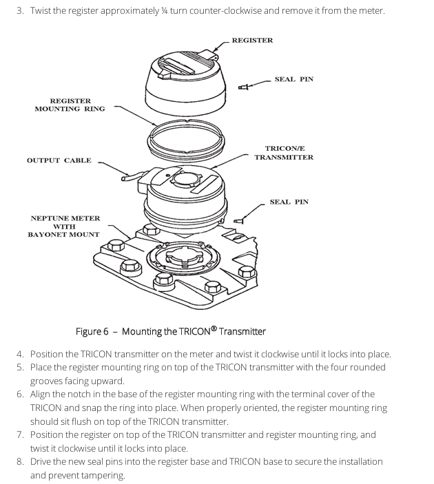
5. Installation of transmitter
If the water meter has installed a register: align the punch with the center of the sealing pin at the bottom of the register, strike with a hammer to break the pin head, and rotate the register counterclockwise by 1/4 turn to remove it.
Install the TRICON transmitter on the water meter and rotate clockwise to lock it; Place the register mounting ring (with four sets of circular grooves facing upwards) on top of the transmitter, align it with the notch on the transmitter terminal cover, and tighten it.
Place the register on the transmitter and mounting ring, rotate clockwise until locked; Insert the new sealing pin into the register base and transmitter base to prevent tampering.
Maintenance and troubleshooting
Core scenarios for troubleshooting
When the electronic flow indication is inconsistent with the mechanical register indication, follow the following steps to troubleshoot:
Abnormal handling measures for items to be verified
Whether the size and type of the transmitter, register, and water meter match, replace them with transmitters or registers that are compatible with the water meter
Does the register rotate smoothly after being installed on the transmitter? Replace or repair the register to solve the problem of excessive torque
Whether the transmitter wiring and power supply are correct, correct wiring errors, and troubleshoot power supply faults
Adjust and calibrate the compatibility and calibration status of the transmitter connection device as required
- OMRON
- ABB
- General Electric
- EMERSON
- Honeywell
- HIMA
- ALSTOM
- Rolls-Royce
- MOTOROLA
- Rockwell
- Siemens
- Woodward
- YOKOGAWA
- FOXBORO
- KOLLMORGEN
- MOOG
- KB
- YAMAHA
- BENDER
- TEKTRONIX
- Westinghouse
- AMAT
- AB
- XYCOM
- Yaskawa
- B&R
- Schneider
- KONGSBERG
- NI
- WATLOW
- ProSoft
- SEW
- ADVANCED
- Reliance
- TRICONEX
- METSO
- MAN
- Advantest
- STUDER
- DANAHER MOTION
- Bently
- Galil
- EATON
- MOLEX
- DEIF
- B&W
- ZYGO
- Aerotech
- DANFOSS
- Beijer
- Moxa
- Rexroth
- Johnson
- WAGO
- TOSHIBA
- BMCM
- SMC
- HITACHI
- HIRSCHMANN
- Application field
- XP POWER
- CTI
- TRICON
- STOBER
- Thinklogical
- Horner Automation
- Meggitt
- Fanuc
- Baldor
- SHINKAWA
- Other Brands
- UniOP
- KUKA
- Iba
- Beckhoff
-
 Mitsubishi MELSEC A2ASCPU PLC System
 -
 PC PMC25.2-002 PLC Module
 -
 B&R X20CP1382 Programmable Controller
 -
 Siemens C98043-A7002-L4 PC Board
 -
 Fanuc A16B-3300-0057 PCB Board
 -
 Schneider LV430403 Circuit Breaker TM160D
 -
 ABB CI810B 3BSE020520R1 PLC Interface
 -
 Omron R88D-HT10 Servo Drive
 -
 Omron CS1G-CPU43H CPU Unit
 -
 Mitsubishi QD70D4 Positioning Module
 -
 Siemens 6FC5110-0BB04-0AA1 Sinumerik 840C CPU
 -
 Siemens 3RT5045-1AC20 SIRIUS Contactor 75kW
 -
 Siemens 3VA2340-5HL32-0AA0 Circuit Breaker 400A
 -
 ABB HBS01-CJC I/O MTUS SD Series Module
 -
 Eberle MT42 Complete PLC Rack PLS514
 -
 Siemens C8451-A201-A9 PLC Card Slot Backplane
 -
 Cherokee ACX643 REV-B Power Supply Unit 100-240VAC
 -
 Schneider SSD1A320BDC1 Solid State Relay 20A
 -
 GE Fanuc IC694APU300 High Speed Counter Module
 -
 Schneider 140DA175300 Analog Output Module
 -
 Allen Bradley 1794-OA8I FLEX 8-Point Digital Output Module
 -
 Phoenix Contact PLC-BPT-24DC/1/SEN Solid State Relay Module
 -
 Schneider IG2000PG2 PLC Module Industrial Controller Card
 -
 Mitsubishi LE-40MTA-E Tension Controller Web Handling Control
 -
 Siemens 6FX1122-1AC02 PLC Card Industrial Interface Module
 -
 ABB AF210-30-11 Contactor Coil Voltage 110-240VAC
 -
 Mitsubishi GT2508-VTBD GT2508-VTBA HMI Touch Screen Panel
 -
 BPT 67200020 Touch Screen PLC Display Multifunction Terminal 50Hz
 -
 NORIS A1-91 PCB Rack Module A1-91-4 A1-91-5 A1-91-6 A1-91-7
 -
 Mitsubishi A1S61PN Power Supply Unit AnS Series 5VDC 5A
 -
 Pilz 312070AA PSSU H PLC1 FS SN SD Safety Module
 -
 Pasaban MTC-3044 PLC Rack with Power Supply Card
 -
 Schneider METSEPM8243 Power Meter PM800
 -
 Fanuc A16B-1212-0100-01 Power Supply Unit
 -
 Honeywell DPCB21010002 PCB IRTP-161 REV A
 -
 Siemens 6ES7315-2AH14-0AB0 CPU 315-2 DP
 -
 Omron GRT1-DA2V Analog Output Module 2 Channels
 -
 Mitsubishi FX3U-128MT/ESS PLC CPU Module
 -
 Schneider SSP05EMA12 Soft Starter Altistart 22
 -
 Mushroom 787602 Push Button Head 40mm
 -
 Hydraulik Elektronik EPM8900 91221 Proportional Module
 -
 ABB XZ C828 A101 Didt Dioder Snubber 3BHE039453R0101
 -
 ABB 3BHE032593R0001 Isolated Power Supply
 -
 ABB 3BHB02722R0001 single-phase charging transformer
 -
 ABB 3BHE006412R0101 UFC762AE101 main control board
 -
 ABB XVC770BE101 3BHE021083R0101 interface board
 -
 ABB 3BHE024747R0101 GD C801 Overvoltage Protection Motherboard
 -
 ABB 3BHE021887R0101 3BHB002751R0102 Variable Frequency Control Board
 -
 ABB SD812 power module 3BSC610023R0001
 -
 Automotive LC4A00010 Brushless Motor Controller
 -
 Doric NC500 Neuroscience Data Acquisition System
 -
 Honeywell X-DCS2000/EN Broadcast Manager
 -
 Kollmorgen S60600 servo drive 6A 480V
 -
 Honeywell 30751044-008 ROM Card
 -
 Honeywell 5SE1-12 Micro Switch Specifications
 -
 Schneider AS-BDAU-204 Analog Output Module
 -
 K93712 Expansion Kit Industrial Module
 -
 MGE DCHEN 3400116300 Circuit Board
 -
 Siemens 6SE7036-1EE85-1HA0 Rectifier Board
 -
 Renesas UPD70F3624GBA1 Microcontroller
 -
 Omron E5AC-CX4A5M-014 Temperature Controller Parameters
 -
 GE IS200TBCIH1BCE Contact Input Board
 -
 Fanuc A05B-2255-C101#EAW Teach Pendant Data
 -
Rieter RMC186C RMC RIO-1 PLC Controller
-
 Siemens PXC24.2-EF32.A Building Automation Controller
 -
 Fanuc A16B-1200-0220 PC Memory Board F3
 -
 Omron CJ2M-CPU33 PLC CPU Module
 -
 Beckhoff EL1918 Safety Input Terminal EtherCAT
 -
 Fanuc A16B-1212-0871 CNC PCB Board
 -
 GE Fanuc IC697BEM713J PLC Module
 -
 Mitsubishi A2ACPU-R21 PLC CPU Module
 -
 Programmable Relay 230V AC 16 Inputs 8 Outputs T2UK
 -
 Schneider F3SP71-4S Safety PLC Module
 -
 NEED-24DC- T2UK Programmable Relay 24V 16in 8out
 -
 Siemens 3RT1075-6SP36 SIRIUS Power Contactor 200kW
 -
 GE 1C31170G02 Printed Circuit Board Module 94V-0
 -
 BPT 67200020 Multifunction Touch Terminal 50Hz
 -
 Fanuc A16B-2200-0931 Option Board with Daughter Cards
 -
 Honeywell FC-SDOL-0424 I/O Module Board
 -
 Lenze EMF2179IB DeviceNet Communication Module
 -
 Yaskawa CIMR-JC4A0007BAA J1000 VFD 0.4kW
 -
 Yokogawa PSBCMNBN Bus Continuation Module ProSafe-PLC
 -
 Phoenix Contact PLC-BPT-24DC/1/SEN Solid-State Relay
 -
 Allen-Bradley 193-EC2AB E3 Plus Overload Relay
 -
 GE DS200TCTGG1AFF Turbine Control Board
 -
 Westinghouse 1C31170G02 Ovation Module
 -
 Mitsubishi A2ACPU21 Programmable Controller Review
 -
 710-95045-AD PLC I/O Operation Console Cable
 -
 Allen-Bradley 1785-L11B PLC-5 Processor Specifications
 -
 BEMAC UST-202-D 1307D V08B2 Circuit Board
 -
 Pilz 312070 PSSu H PLC1 FS Safety Module
 -
 Keyence QS-MB1 Safety Network Module Overview
 -
GE Fanuc IC693CPU372 CPU Module 90-30 Series
-
 Mitsubishi RJ71EIP91 EtherNet/IP Module
 -
 Schneider LXM62DD27D21000 Lexium 62 Servo Drive
 -
 Mitsubishi Q13UDEHCPU Universal PLC CPU Module
 -
 B&R X20CP3585 Programmable Controller X20 CPU
 -
 Siemens 6FC5203-0AF02-0AA0 Sinumerik Operator Panel
 -
 IWKA PG02 VKR TEL-Z Self-Sufficient Measuring System
 -
 Schneider BMXCPS2010 PLC Power Supply Modicon M340
 -
 Mitsubishi A171SCPU Motion Servo CPU Specifications
 -
 PLC Board with Finder 44.52 Relay Module 6A 250V
 -
 Honeywell DOP 09436601 Measurex Module Data
 -
 Fanuc A20B-8101-0320 CNC Circuit Board
 -
 KUAX 680I V.24 PLC Module 68142304
 -
 Allen Bradley 1785-L30B PLC 5/30 Processor
 -
 Phoenix ILC 191 ETH 2TX 2700976 Ethernet Controller
 -
 Siemens 6SY7000-0AC80 PLC Power Supply Module
 -
 Reliance Electric MACS 804.46.20 CWW PLC Drive
 -
 Omron CP1E-N60DR-D PLC CPU 36 Input 24 Output
 -
 Mitsubishi Melsec PLC System A2ACPU A63P AY13E AX82
 -
 Square D PAF361600DC1680 2000A Circuit Breaker
 -
 MERLIN GERIN STR 58U 5000A Electronic Trip Unit
 -
 Omron CJ1W-SCU21-V1 Serial Communication Unit
 -
 SICK S30A-6011EA S3000 Safety Laser Scanner
 -
 Mitsubishi Q00JCPU-S8 Universal Programmable Controller
 -
 Allen-Bradley 20AB9P6C3AYNANC0 PowerFlex 70 AC Drive
 -
 SYSMELEC Handheld Robot Automation Controller
 -
 LG Display LB315WRM-SVA1 32 Inch 4K LCD Panel
 -
 Mitsubishi Kakoki E Series PLC I/O Modules
 -
 Allen-Bradley 1440-VST02-01RA Dynamic Measurement Module
 -
 Beckhoff EL5042 EtherCAT Encoder Terminal
 -
 Beckhoff CX5010-0112 Embedded PC Controller
 -
 Guardmaster 440R-D22R2 Safety Relay Specifications
 -
 NL12880BC20-10ND Industrial Display Panel Data
 -
 LFI 12X5326-S1 Slide-in Control Board Technical Data
 -
 Modicon AS-9370-001 Programmable Controller Data
 -
 Mitsubishi Kakoki E-01B-4130 PLC Module Overview


