
Moxa EDS-508A series network managed Ethernet switch
Moxa EDS-508A series network managed Ethernet switch
Initialization configuration: three management interface operations
EDS-508A supports three initial configuration methods: serial port console, Telnet console, and web browser. Please note that the default IP address is 192.168.127.253, subnet mask is 255.255.255.0, and the PC needs to be on the same logical subnet as the switch to access through the network interface.
1. Serial console configuration (preferred when no IP)
Hardware connection: Connect the console port of the switch to the COM port of the PC using an RJ45 to DB9 cable;
Parameter settings: baud rate 115200, no checksum (None), data bit 8, stop bit 1, terminal type VT100 (recommended to use Moxa PComm Terminal Simulator software);
Login process: Select terminal type 1 (ansi/vt100), login account as admin (read-write permission) or user (read-only permission), default no password, can be set as needed (maximum 16 characters).
2. Telnet Console Configuration
Prerequisite: The PC and switch are on the same subnet, and physical connections can be made using either direct or crossover Ethernet cables;
Operation steps: Enter telnet 192.168.127.253 through Windows' Run ', and the subsequent terminal type selection and login process should be consistent with the serial port console;
Attention: Check "VT100 Arrows" in the terminal preference settings to ensure proper cursor navigation.
3. Web browser configuration (easiest to use)
Access method: Enter the switch IP (such as 192.168.127.253) in the browser address bar, and log in with the admin/user account;
Interface features: The left navigation bar categorizes and displays all configuration items, supports visual operations, and is suitable for non professional technicians to quickly get started;
Security advice: If remote management is not required, Telnet and web access can be disabled through the serial port console to reduce security risks.
Detailed Explanation of Core Function Configuration
1. Basic settings: System and network parameters
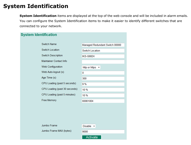
(1) System Identification and Security
System information: The switch name (such as "Factory Line 1 Switch"), location, and contact information of the maintenance personnel can be configured. The information will be displayed at the top of the web console and in the alarm email;
Password management: The admin account has full permissions, while the user account only has read-only permissions and supports password modification (requires repeated input confirmation, can clear password and restore default);
IP access control: Use the 'Accessible IP List' to restrict access to the switch to only specified IPs or subnets (such as allowing only 192.168.1.0/255.255.255.0 network segments), and allow all IPs to access when not enabled.
(2) Ports and network parameters
Port settings: Configure port enable/disable, transmission rate (auto negotiate or fixed 10M/100M full/half duplex), flow control (FDX Flow Ctrl), MDI/MDIX mode (default auto detect);
Network configuration:
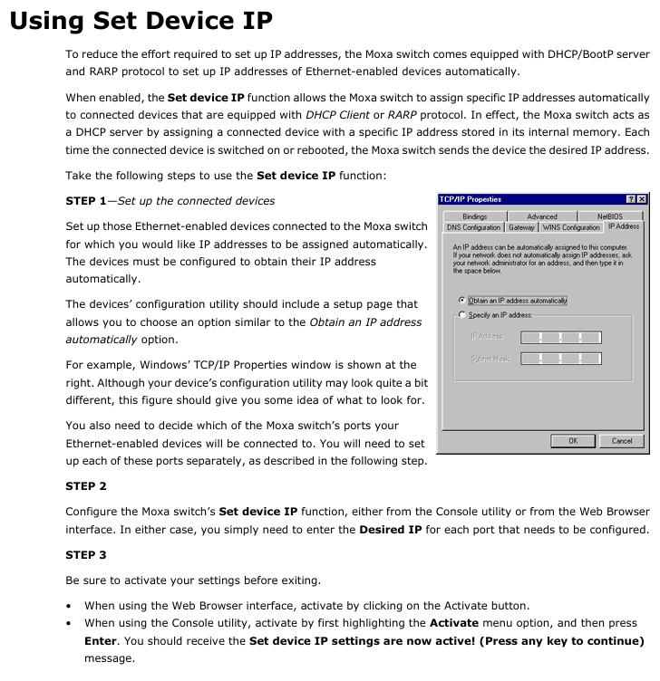
IPv4: supports manual setting of IP, subnet mask, gateway, or automatic acquisition through DHCP/BootP;
IPv6: Supports link local address (automatically generated) and global unicast address (requires prefix configuration);
DNS: Primary and backup DNS servers can be set up, supporting access to switches through domain names (DNS needs to be configured first).
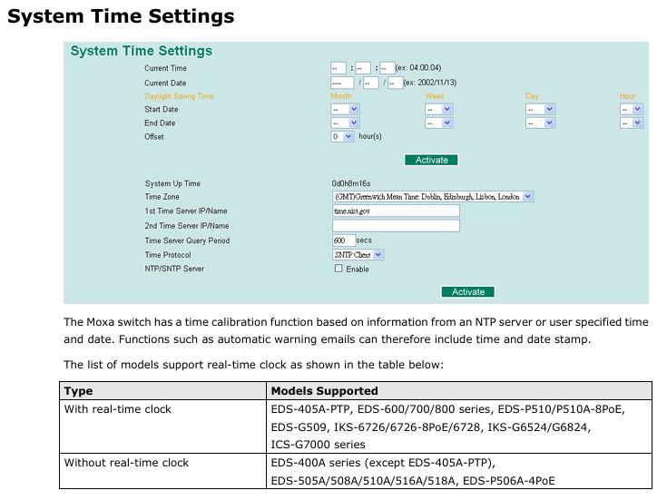
(3) Time management
Time synchronization: Supports NTP/SNTP clients, configurable primary and backup time servers (such as time. nist. gov), with a default query cycle of 600 seconds;
Time zone and daylight saving time: The default GMT time zone allows for manual setting of daylight saving time start/end dates and time offsets;
Attention: Models without real-time clock (such as EDS-508A) require time synchronization after restart. It is recommended to configure NTP server for automatic calibration.
2. Network reliability: redundancy and traffic control
(1) Turbo Ring Redundancy (Industrial Scene Core)
Enabling method: Through the top DIP switch (switch 4) or software configuration, Turbo Ring v2 protocol is supported by default, with recovery time< 20ms@250 Switch;
Attention: If VLAN or port aggregation needs to be enabled on the last 4 ports, Turbo Ring cannot be activated through DIP switches and must be configured through software.
(2) Port Trunking
Function: Bind multiple ports into an aggregation group (up to 4 groups, with a maximum of 8 ports per group), increase bandwidth (e.g. aggregate 8 100BaseTX full duplex ports to achieve a bandwidth of 1.6Gbps), and achieve redundancy;
Mode selection: Supports static aggregation (Moxa private protocol) and LACP (IEEE 802.3ad standard). After configuration, the VLAN, multicast filtering, and other settings of the port will be reset to default;
Applicable models: EDS-508A supports 2 aggregation groups, with different numbers of aggregation groups for different models (e.g. EDS-518A supports 3, EDS-728 supports 4).
(3) Traffic Priority (QoS)
Core mechanism: Based on IEEE 802.1p (Layer 2) and TOS/DiffServ (Layer 3) labels, traffic is divided into four priority queues (high/medium/normal/low);
Queue scheduling: Supports two modes: "Weight Fair (8:4:2:1 weight)" and "Strict". The default is Weight Fair to avoid low priority traffic from starving;
Industrial adaptation: Supports IEC 61850 QoS and can set GOOSE/SMV/PTP and other power automation protocol messages as high priority to ensure real-time performance.
3. Network isolation: VLAN configuration
(1) VLAN mode and type
Support type:
IEEE 802.1Q VLAN: Label based logical isolation, supporting three port types: Access (single VLAN without labels), Trunk (multi VLAN with labels), and Hybrid (removable egress labels);
Port type VLAN: VLAN is divided based on physical ports, with simple configuration but low flexibility. When enabled, IGMP Snooping will be automatically disabled;
Unaware VLAN: does not check VLAN tags, only transmits all tagged messages transparently, suitable for serial connection in other VLAN networks.
(2) Typical application examples
Scenario: Switch A connects devices A (VLAN5), B/C (VLAN2), D (VLAN3), and E (VLAN4), and is interconnected with switch B through Trunk port 3;
to configure:
Device A port is set to Access, PVID=5;
Set the B/C ports of the device to Trunk, PVID=2, and fixed VLAN (tagged)=3/4;
Set the interconnection port of the switch to Trunk and enable the GVRP protocol to automatically synchronize VLAN information;
Set the corresponding port of switch B to Access, and match PVIDs with VLAN2/3/4/5 to ensure normal cross switch VLAN communication.
4. Multicast filtering: reducing network storms
Core agreement:
IGMP Snooping (IP layer): Supports v1/v2/v3, and only forwards multicast traffic to ports that have joined the group by listening to IGMP report/query messages to avoid flooding;
GMRP (MAC layer): dynamically registers multicast addresses, suitable for devices that do not support IGMP;
Static multicast MAC: Manually add multicast addresses and port bindings, suitable for devices that only support multicast but do not have IGMP/GMRP.
Configuration points: After enabling IGMP Snooping globally, it needs to be enabled separately by VLAN; Support 'Enhanced Mode', only forwarding multicast to member ports to reduce redundant traffic.
5. Bandwidth management and security protection
(1) Bandwidth control
Broadcast storm protection: supports limiting port broadcast/multicast/unknown unicast traffic rates (such as 8M), and can temporarily disable ports when exceeded (default disable for 30 seconds);
Entrance/exit speed limit: Configure the entrance/exit speed according to the port (such as limiting it to 10% of the total bandwidth) to avoid single devices occupying too much bandwidth.
(2) Security protection
User authentication: Supports centralized authentication using TACACS+and Radius, replacing local accounts and suitable for large-scale networking;
Port access control:
Static Port Lock: Bind a specific MAC address to a port and only allow communication with that MAC address;
IEEE 802.1X: Based on the client authentication server (such as Radius) - authenticator (switch) architecture, unauthenticated devices cannot access;
ACL access control list (only supported by layer 3 switches): Filter packets based on IP/MAC address, protocol (TCP/UDP), and port number (such as denying access to 192.168.2.0/24 network segment 192.168.0.1).
6. Alarm and diagnosis: rapid fault location
(1) Auto Warning
Email Alert: Configure SMTP servers (such as enterprise email) and recipient addresses (up to 4), triggering events including switch cold start, port link disconnection, traffic overload, configuration changes, etc;
Relay alarm: supports 2-channel relay output, can be associated with key events such as power failure and Turbo Ring breakage, and trigger external sound and light alarms;
Test verification: After configuration, a test email can be sent to confirm that the alarm channel is normal.
(2) Diagnostic tools
Mirror Port: Copy the inbound/outbound/bidirectional traffic of a specified port (monitored port) to the mirror port, and connect packet capture tools (such as Wireshark) to analyze network issues;
Ping test: initiate Ping requests from the switch (not PC initiated) to detect the connectivity between the switch and the target IP;
LLDP protocol: automatically obtains neighbor device information (such as neighbor IP, port, model), supports MXview software to automatically generate network topology.
(3) Monitoring and Logging
Real time monitoring:
Switch level: View the total traffic of all ports, unicast/multicast/broadcast packet rates;
Port level: View the sending and receiving speed and error packet count of a single port;
SFP monitoring: Check the temperature, voltage, and light emitting and receiving power of the optical module (with an error of ± 3dBm);
Log management: Record events such as cold start, configuration changes, authentication failures, port disconnections, etc. It supports exporting log files or sending them to Syslog servers (up to 3 configured).
EDS Configurator: Batch Management Tool
EDS Configurator is a Windows platform specific GUI tool (available for free download from the Moxa official website) that supports batch operation of multiple switches. Its core functions include:
Device search:
Broadcast search: Discover all switches within the same LAN (no need to know IP);
IP search: specify an IP address to locate a single switch (supporting cross WAN/Internet);
Batch configuration:
Firmware upgrade: Select multiple switches to update firmware uniformly (download. rom file in advance);
IP modification: Batch modify switch IP, subnet mask, gateway, support DHCP enable/disable;
Configuration import and export: Export the configuration of a switch as a text file and import it to other devices of the same model to achieve rapid deployment;
Device unlocking: For password protected switches, enter the admin password to unlock, and subsequent operations do not require repeated input.
SNMP and MIB: Remote Monitoring Integration
SNMP version: Supports v1/v2c (community string authentication, default public read-only, private read-write) and v3 (supports MD5/SHA authentication and data encryption, with the highest security);
Trap settings: Configure primary and backup Trap servers to automatically send Trap information when triggering events such as link disconnection or authentication failure;
MIB support:
Standard MIB: including MIB-II (system, interface, IP, TCP/UDP, etc.), dot1dBridge (spanning tree) qBridgeMIB(VLAN);
Private MIB: Provides Moxa-EDS-508A-MIB.my files, supporting monitoring of device specific parameters such as Turbo Ring status and PoE power.
Precautions and Applicable Scenarios
Model compatibility: Some features are only supported by specific models (such as PoE only for PoE models, ACL only for layer 3 switches), and the device model needs to be confirmed before configuration;
Industrial environment adaptation: Supports wide temperature range (-40~75 ℃, with "- T" model), anti electromagnetic interference (ESD contact 6kV/air 8kV), suitable for harsh environments in industrial sites;
Factory reset: It can be executed through serial port/Telnet/web console. After recovery, the default IP (192.168.127.253) needs to be used to reconnect;
Summary
The Moxa EDS-508A series switches offer rich industrial grade features such as Turbo Ring redundancy QoS、802.1X)、 Multi interface management method and batch configuration tool meet the requirements of industrial scenarios for network stability, security, and maintainability. The manual covers the entire process from initialization to advanced configuration in detail, suitable for network administrators and industrial automation engineers to refer to, helping to quickly deploy and operate industrial Ethernet.
- OMRON
- ABB
- General Electric
- EMERSON
- Honeywell
- HIMA
- ALSTOM
- Rolls-Royce
- MOTOROLA
- Rockwell
- Siemens
- Woodward
- YOKOGAWA
- FOXBORO
- KOLLMORGEN
- MOOG
- KB
- YAMAHA
- BENDER
- TEKTRONIX
- Westinghouse
- AMAT
- AB
- XYCOM
- Yaskawa
- B&R
- Schneider
- KONGSBERG
- NI
- WATLOW
- ProSoft
- SEW
- ADVANCED
- Reliance
- TRICONEX
- METSO
- MAN
- Advantest
- STUDER
- DANAHER MOTION
- Bently
- Galil
- EATON
- MOLEX
- DEIF
- B&W
- ZYGO
- Aerotech
- DANFOSS
- Beijer
- Moxa
- Rexroth
- Johnson
- WAGO
- TOSHIBA
- BMCM
- SMC
- HITACHI
- HIRSCHMANN
- Application field
- XP POWER
- CTI
- TRICON
- STOBER
- Thinklogical
- Horner Automation
- Meggitt
- Fanuc
- Baldor
- SHINKAWA
- Other Brands
- UniOP
- KUKA
- Iba
- Beckhoff
- ADLINK
-
 GE Fanuc VMIVME-5588 High-speed Reflective Memory Board
 -
 VMIC VMIVME-5565 Reflective Memory Board
 -
 VMIC VMIVME-2127 Voltage Source Digital Output Board
 -
 VMIC VMIVME 4512 Analog VME Process PCB Assembly
 -
 GE Fanuc VMIVME-3122-022 Analog I/O Module
 -
 VMIC VMIVME 5576 High Speed Fiberoptic Network Board
 -
 FANUC VMIVME-7452 VMEbus Analog I/O Board
 -
 FANUC VMIVME-2210 VMEbus Digital Output Board
 -
 FANUC VMIVME-7750-734000 VMEbus Single Board Computer
 -
 VMIC VMIVME 2210 VMEbus DO 28V Digital Output Board
 -
 VMIC VMIVME DR11W VMEbus DMA Interface Module
 -
 VMIC VMIVME-2536-200 5V Optically Coupled Digital I/O Board
 -
 VMIC VME-7754 VMIVMF7754-259000 VMEbus Control Card
 -
 VMIC 2170A VME Interface Board
 -
 GE VMIC PMC-5565PIORC-210000 Reflective Memory PMC Node Card
 -
 VMIC VMIVME-7750-750000 VME Single Board Computer
 -
 VMIC VMIVME-7751 VME Single Board Computer
 -
 VMIC 332-004512 Analog VME Process Board
 -
 VMIC VMIVME2528 VME Interface Board
 -
FANUC VMIVME-2120 VME Bus Interface Board
-
 FANUC VMIVME-2540 VME Bus Interface Board
 -
 FANUC VMIVME-3230 VME Bus Interface Board
 -
 FANUC VMIVME-4514 VME Bus Interface Board
 -
 ETEL DSB2S154-211E-000H Servo Amplifier
 -
 ETEL DSCQT112-111-000 Motion Control Module
 -
 ETEL LMG20-050-3QB-211A Servo Motor – High Torque Linear
 -
 ETEL EU-LCP-0-0-1000-01 Communication Card
 -
 ETEL DSA2P174ZA-033A Servo Amplifier Driver
 -
 ETEL EA-P2M-400-15/40A-0100-00 Servo Driver
 -
 ETEL DSC2P152-111-000 Servo Drive Amplifier
 -
 ETEL LMS15-050-3UA-209A Linear Motor
 -
ETEL DSC2P152-111D-000A Controller
-
 ETEL DSB2P131-111E-000B Digital Servo Amplifier Position Controller
 -
 ETEL DSO-PWR111C-000B Power Supply Module
 -
 ETEL DSCDP324-321F-000C Servo Driver
 -
 ETEL DSC2P152-111B-000D Controller
 -
 ETEL DSB2P142-111E-000H Circuit Board
 -
 ETEL LMG05-030-3QA-H01 Linear Motor
 -
 ETEL DSC2P152-111F-000A Controller
 -
 ETEL DSA2S211ZA Servo Drive
 -
 ETEL DSCDM332-112-000 Drive Module
 -
 ETEL DSCDP334-421-000 Digital Position Controller Servo Drive
 -
ETEL EA-P2M-400-15/40A-0100-00 AccurET Servo Drive
-
 ETEL TMA0140-050-3UB-202B Torque Motor
 -
 ETEL DSA1DL1D.PCB Servo Drive Board
 -
 ETEL DSA2DL 1A Servo Drive
 -
 ETEL DSMAX111B-000B Servo Drive
 -
ETEL DSO-PWS111C-000B Power Supply Module
-
 ETEL DSC2P142-111B-000D Servo Drive Amplifier
 -
 ETEL DSC2P132-111D-000A Servo Drive Amplifier
 -
ETEL DSC2P152-111B-000D Servo Drive Amplifier
-
ETEL DSB2P131-121E-000H Servo Drive Amplifier
-
 ETEL DSB2P142-111E-000H Servo Drive Amplifier
 -
ETEL DSO-PWR112C-000A Power Supply Module – High Power
-
ETEL DSO-PWR111C-000A Power Supply Module
-
ETEL DSB2P121-121E-000H Servo Drive Amplifier
-
 ETEL DSB2S134-111E-000H Digital Servo Amplifier
 -
 ETEL RTMA0140-070-AQN-21E Motor
 -
ETEL DSCDP132-111-000 Dual Controller Circuit Board – Motion Control
-
 ETEL LMS15-050-3UA-209Aft Linear Motor
 -
 ETEL DSCDP324-322G-000A Position Controller
 -
ETEL DSA2P174ZA-033A Servo Amplifier Driver
-
 ETEL DSA2P174ZA-017A Servo Amplifier Driver
 -
 ETEL LMD10-050-3QA-223A Linear Motor
 -
ETEL EU-LGP-0-0-1000-00 PCI Network Card
-
ETEL DSO-PWS111C-000B Power Supply Module
-
ETEL DSC2V174-111C-001A Servo Controller
-
 ETEL EA-P2M-600-15/40A-0000-01 AccurET Modular Position Controller
 -
 ETEL RTMA0140-070-AQN-21B DD Motor
 -
 ETEL DSC2P144-421-000 Servo Driver
 -
ETEL EA-P2M-400-15-40A-0100-00 Servo Drive
-
ETEL DSCDM341-111C-000B Board
-
 ETEL LMD10-050-3QA-223A Motor
 -
ETEL RTMA0140-070-AQN-21E DD Motor
-
 ETEL DSCDM342-111-000 Servo Variator
 -
ETEL DSC2P152-111E-000A Servo Amplifier
-
ETEL LMS15-050-3UA-209A Motor
-
ETEL RTMA0140-070-AQN-21C DD Motor – High Torque Direct Drive
-
 ETEL DSCDP334-421G-000A Servo Drive
 -
Etel DSB2S154-211E-000H Digital Servo Amplifier
-
 ETEL EA-P2M-400-15/40A-0100-00 AccurET Servo Drive
 -
 ETEL DSA2P-174ZA-017A Digital Servo Amplifier
 -
ETEL EA-P2M-400-15/40A-0100-00 Servo Drive
-
ETEL LMP07-100-3TAS-229 Linear Motor Primary Part
-
ETEL LMA11-120-3ZA-359A Linear Motor
-
 ETEL EA-S0M-400-40/80A-0000-00 Drive Power Supply
 -
Etel DSCDP334-421-000 Driver
-
ETEL DSCDM341-111C-000B DSCDM Drive Board
-
Etel DSA1 Digital Servo Amplifier
-
ETEL DSA2P174ZA-033A Servo Amplifier
-
ETEL DSCDM342-111-000 Servo Verifier
-
 ETEL LMS15-050-3UA-209A Linear Motor
 -
ETEL P2M-048-2.5/5A AccurET Position Controller – Modular
-
ETEL LMD10-050-3QA-223A Linear Motor – Compact Precision
-
 ETEL EA-P2M-400-05/10A-0000-01 Drive – Precision Motion
 -
ETEL LMP07-100-3TAS-229 Linear Motor Primary Part
-
 ETEL EU-LGP-0-0-0000-00 Motion Control Card – Precision Control
 -
 ETEL DSC2P152-111E-000A Servo Amplifier
 -
ETEL EA-P2M-400-15/40A-0100-01 Servo Drive
-
 ETEL EA-SOM-300-40/80A-0000-00 AccurET Power Supply Module
 -
ETEL LMG10-1050-3QA-H01 Linear Motor
-
 ETEL EA-SOM-300-40/80A-0000-00 AccurET Modular Power Supply
 -
ETEL EA-P2M-400-15/40A-0100-00 AccurET Servo Drive
-
 ETEL EA-P2M-400-15/40A-0100-01 Servo Driver
 -
Etel RTMA0140-070-AQN-21B High Speed Motor
-
ETEL DSC2P141-111-000 Linear Servo Amplifier
-
ETEL DSB2S134-211E-000H Digital Servo Amplifier
-
ETEL 3LM-23C Motion Controller
-
Etel DSO-SER211-000 Power Add-On Board
-
ETEL DSCDP334-421-000 Servo Drive
-
 CTI-Cryogenics 8116071G001 Enhanced On-Board 8F Cryopump
 -
ETEL LMD10-050-3QA-223A Linear Motor
-
Etel DSO-SER211-000 Servo Card Power Add-On
-
ETEL LMG05-050-3QA-213A Linear Motor
-
Etel DSO-SER211-000 Power Add-On Board
-
ETEL EU-LGP-0-0-0000-00 Motion Control Card
-
ETEL EA-P2M-400-15/40A-0100-00 AccurET Servo Drive
-
 ETEL DSA2P1540A Digital Servo Amplifier
 -
ETEL DSC2P131-111-000 Drive Board
-
ETEL DSC2P131-111D-000A Servo Drive
-
Etel SA-IL 03-208 Linear Motor Section 208mm
-
 ETEL EA-P2M-300-4/7.5A-0000-01 AccurET Position Controller
 -
ETEL DSO-SER211-000 Power Board
-
ETEL DSC2P131-111F-000A Servo Amplifier
-
ETEL DSA1P6242B Digital Servo Amplifier
-
ETEL DSC2P131-111B-000B Regulator
-
ETEL DSA2P1540A Digital Servo Amplifier
-
ETEL EA-P2M-048-2.5/5A-0100-01 Drive


