
Foxboro FBM224 Modbus ® communication module
Communication function and protocol support
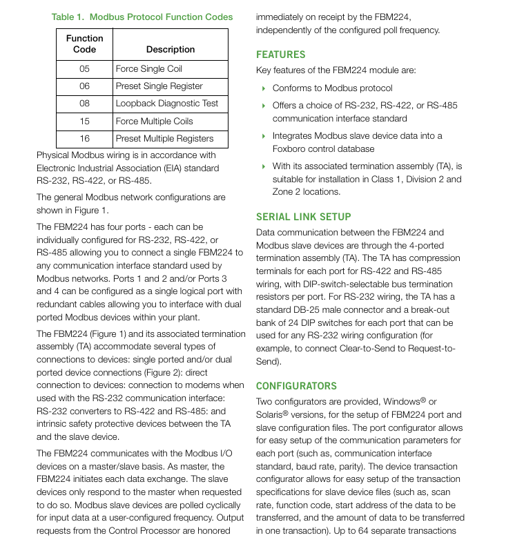
1. Modbus protocol adaptation
Working mode: only supports Modbus RTU mode (asynchronous communication), does not support ASCII mode;
Function code support: Covering commonly used core industrial function codes to meet all data reading and writing requirements, as follows:
Function code function description application scenario
01 Read coil status, read digital output status (such as valve switch, indicator light status)
02 Read input status Read digital input status (such as sensor trigger signals, equipment fault feedback)
03 Read and hold registers to read device configuration parameters, cumulative data, etc. (such as cumulative flow rate of flow meters)
04 Read input register to read real-time measurement data (such as analog conversion values of temperature, pressure, and flow)
05 Mandatory single coil control for single digital output (such as starting/stopping motors, opening/closing valves)
06 Preset single register configuration device for individual parameters (such as setting pressure threshold, flow upper limit)
Self check the communication link between the 08 circuit diagnostic testing module and the slave device to troubleshoot connection faults
15. Mandatory batch control of multiple digital outputs with multiple coils (such as simultaneously starting a group of devices)
16 preset multi register batch configuration of device parameters (such as batch setting of measurement ranges for multiple instruments)
Data format: Supports 8-bit characters, configurable parity check (odd check/even check/no check), configurable stop bit (1 bit/2 bits), adaptable to communication parameter settings of different slave devices.
2. Port configuration and communication capability
(1) Port characteristics
The module is equipped with four independent serial communication ports, each of which can be individually configured as an RS-232, RS-422, or RS-485 interface without the need for hardware modification. Switching can be completed through software configurator;
Port redundancy function: Ports 1&2 and 3&4 can be configured as a single logical port, and can be connected to dual port Modbus devices with redundant cables to achieve communication link redundancy and avoid data interruption caused by single point failures.
(2) Communication parameters
Transmission rate: Supports 10 speeds including 300, 600, 1200, 2400, 4800, 9600, 19200, 38400, 57600, and 115200 baud, and can be flexibly selected according to communication distance and device requirements (low-speed is recommended for long-distance communication, high-speed is recommended for short distance high-speed transmission);
From device address: Supports a range of 1-247 addresses, which can cover the addressing requirements of Modbus devices in the vast majority of industrial scenarios.
3. Data interaction capability
(1) Access capacity
A single module can support up to 64 Modbus slave devices (the actual number is affected by device type, data volume, and scanning rate);
A single module can support up to 2000 distributed control interface (DCI) data connections, covering:
2000 analog I/O values (integer or IEEE single precision floating-point type);
32000 digital I/O values (calculated by packing 32 digital points per connection);
Mixed analog and digital data connection.
(2) Data processing and updating
As a Modbus master, the module periodically polls the input data from the device according to the user configured scanning rate, and the output request is immediately executed after being sent by the control processor, without being limited by the polling cycle;
The access speed of the control station to FBM224 data can reach up to 500ms at the fastest, with low data update latency, meeting real-time control requirements;
Support data format conversion: The module automatically converts raw data from the device (2-byte/4-byte signed/unsigned integers, 4-byte IEEE floating point types, binary values) into Foxboro system compatible format and stores it in the system database for use by plant management functions and operator interfaces; Simultaneously supporting byte order and bit order switching, adapting to data storage formats of devices from different manufacturers.
Configuration tools and operating procedures
1. Configuration tool
Provide Windows ® Compared to Solaris ® There are two versions of configurator for operating systems, namely port configurator and device transaction configurator. During the configuration process, the validity of parameters (such as rate range and address legality) is automatically verified to avoid configuration errors.
(1) Port configurator
Used to set communication parameters for each port, including:
Communication interface standard (RS-232/RS-422/RS-485);
Transmission rate, parity check, stop bit;
Enable/disable port redundancy mode (1&2 ports, 3&4 ports).
(2) Device Transaction Configurator
Used to set communication transaction parameters for slave devices, including:
Scanning rate: configurable from 0.5 seconds to 255 seconds, default 500ms, adjustable according to device response speed and real-time data requirements;
- OMRON
- ABB
- General Electric
- EMERSON
- Honeywell
- HIMA
- ALSTOM
- Rolls-Royce
- MOTOROLA
- Rockwell
- Siemens
- Woodward
- YOKOGAWA
- FOXBORO
- KOLLMORGEN
- MOOG
- KB
- YAMAHA
- BENDER
- TEKTRONIX
- Westinghouse
- AMAT
- AB
- XYCOM
- Yaskawa
- B&R
- Schneider
- KONGSBERG
- NI
- WATLOW
- ProSoft
- SEW
- ADVANCED
- Reliance
- TRICONEX
- METSO
- MAN
- Advantest
- STUDER
- DANAHER MOTION
- Bently
- Galil
- EATON
- MOLEX
- DEIF
- B&W
- ZYGO
- Aerotech
- DANFOSS
- Beijer
- Moxa
- Rexroth
- Johnson
- WAGO
- TOSHIBA
- BMCM
- SMC
- HITACHI
- HIRSCHMANN
- Application field
- XP POWER
- CTI
- TRICON
- STOBER
- Thinklogical
- Horner Automation
- Meggitt
- Fanuc
- Baldor
- SHINKAWA
- Other Brands
- UniOP
- KUKA
- Iba
- Beckhoff
- ADLINK
-
 Basler Electric 9289902106 Circuit Board
 -
 Basler Electric BE1-32R Protective Relay A1E E1P BOS1P
 -
 Basler Electric RAL6144-16GM GigE Line Scan Camera with Lens
 -
 Basler Electric BE3-49R-5I5A1 Temperature Relay
 -
 Basler Electric BE1-32R Power Relay B3E E1R A0N1F
 -
 Basler Electric SR4A2B06B3A Static Voltage Regulator Features
 -
 Basler Electric 9121000106 Manual Voltage Control MVC Guide
 -
 Basler Electric SR32A-2B15B3E Static Voltage Regulator
 -
 Basler Electric SR4A2B06B3A Static Voltage Regulator Guide
 -
 Basler Electric 801A193F02 Hammond Transformer Module
 -
 Basler Electric BE1-24 Volts Per Hertz Relay A1E F1J D1S0F
 -
 Basler Electric AEC63-7 Analog Excitation Controller 220-277V
 -
Basler Electric BE132R Power Relay T245579
-
 Basler Electric MVC 108 Manual Voltage Control 90 37000 102
 -
 Basler Electric 9022900-103 Control Transformer 6-7VA 60Hz
 -
 Basler Electric BE1-79M Plug Adapter 9170111102
 -
 Basler Electric 9 2007 00 100 Current Boost System CBS 305
 -
 Basler Electric SR4A2B01B3A Static Voltage Regulator 120V
 -
Basler Electric BE1-32R Power Solid State Relay E2E A10 A0N0F
-
 Basler Electric PRS250 Veri-Sync Relay 9088800102
 -
 Basler DECS 125-15-B2C Digital Excitation Control
 -
 Basler BE 13693 002 Transformer
 -
Basler BE1-59N Ground Fault Overvoltage Relay
-
 Basler BE1-79A Reclosing Relay
 -
 Basler 9-1051-00-105 Overload Protection Module
 -
 Basler BE1-32R Power Relay – Directional Overcurrent Guide
 -
 Basler 9319700103 BE3-27T/59T-3A1N3 Voltage Relay
 -
 Basler BE1-87G Generator Differential Relay
 -
 Basler BE3-25-1D1N4 9319100106 480V Relay
 -
 Basler SR8A2B07B3A Static Voltage Regulator
 -
 Basler Electric BE4-27/59 Over/Under Voltage Relay 307-2552
 -
Basler Electric SR32A2B05B3E Static Voltage Regulator
-
Basler Electric BE1-27 A3E C3J A1N6F Solid State Protective Relay
-
 Basler Electric 9174700-100 Excitation Limiter Generator
 -
 Basler Electric BE1-87G Generator Differential Relay 09833
 -
 Basler Electric 9310200100 Power Supply Module
 -
 Basler Electric TIEE1CD0N07 Control Module
 -
Basler Electric BE1-59N Ground Fault Relay T214750
-
Basler Electric SR8A2B10B3AX Static Voltage Regulator 9060200126
-
 Basler Electric SSR 125-12 Voltage Regulator
 -
 Rolls Royce H1111.0204 Ship Main Controller
 -
 Basler Electric BE3-32-3AC Reverse Power Relay 9 1376 00 105
 -
Basler Electric BE3-25-1A1N4 Synch Check Relay 9319100100
-
 Basler Electric SR4A-2B15B3A Static Voltage Regulator
 -
 Basler Electric SR4A-2B15B3E Static Voltage Regulator
 -
 Basler Electric 9170818100 Solid State Protective Relay
 -
 Basler Electric AEC63-7 Analog Excitation Controller
 -
 Basler Electric 17483 Auxiliary Module
 -
Basler Electric BE1-59 Over Voltage Relay
-
Basler Electric 21600-101 Control Module
-
 Basler Electric KR2F Generator Voltage Regulator 9056600100
 -
 Basler BE1-CDS Current Differential System
 -
 Basler Electric CBS 212 Current Boost System 9 2650 00 100
 -
 Basler Electric IFM-150 Firing Circuit Chassis
 -
 Basler Electric BE1-60 Voltage Balance Relay C1F A1P D0C3F
 -
Basler Electric BE1-32R Power Relay A2E D1R A0N0F
-
Basler Electric BE1-32R Power Relay A2E D1R A0N0F
-
 Basler Electric 8650C80G01 Isolation Transducer PCB Board
 -
 ETEL EA-P2M-300-4/7.5A-0100-01 AccurET Modular 300 Servo Drive
 -
 Basler Electric 87T Transformer Differential Relay
 -
Basler Electric BE-6868 Power Transformer 5950007559202
-
 Basler Electric PRS250 Veri-Sync Relay 9088800102
 -
 Basler Electric SCP-250-G-60 VAR Power Factor Controller
 -
 Basler DECS-150 AVR 1NS2V1N1S Voltage Regulator
 -
Basler UFOV 260A Under Frequency Overvoltage Module
-
 Basler MOC2 199 Motor Operated Control – Overview and Setup
 -
 Basler BE3-49R-5K5A1 Temperature Relay – Complete Guide
 -
Basler BE 20035 001 Transformer – Technical Data and Installation
-
 Basler BE 02727 001 Transformer – Specifications and Usage
 -
 Basler BE127 Under Voltage Relay – Features and Application Guide
 -
Basler CBS377 Current Boost System – Complete Technical Guide
-
Basler BE1-87G P/N 9170818100 Differential Relay – In-Depth Specs
-
Basler BE1-87G Generator Differential Relay – Technical Overview
-
Basler Electric SR4A2B16 SVR Static Voltage Regulator – Complete Guide
-
 Basler Electric 9261500101 Power Supply Module
 -
 Basler Electric AEM-2020 Analog Expansion Module
 -
Basler Electric DGC-2020 Digital Genset Controller 51BRBNEAH001
-
Basler Electric BE1-59N Ground Fault Overvoltage Relay
-
Basler Electric BE1-59N-A5E-E1L-N0S1F Neutral Overvoltage Relay
-
Basler Electric MOC2499 Motor Operator Control Potentiometer 9072300430
-
 Basler Electric BE1-50/51M Overcurrent Relay
 -
 Basler Electric 9148100106 MOC3502 Solid State Relay 250VDC 0.25A
 -
 Basler Electric CBS 212 Current Boost System 9265000100
 -
Basler Electric 10493002 Control Module
-
Basler BE1-32R D3E E1R A0N1F Power Relay
-
 Basler SR8A2B15B3A Static Voltage Regulator
 -
 Basler IFM-105 Firing Circuit Chassis 9324100105
 -
Basler SR4A2B05B3A Static Voltage Regulator
-
 Basler BE151G1EB6PB0N0F Protective Relay
 -
Basler BE1-59 Electric Over Voltage Relay
-
 Basler 277 Static Programmable Powerline Carrier Channel
 -
Basler BE1-32R D1E A1P A0N1F Power Relay
-
Basler SR4A1B07B3A Static Voltage Regulator
-
 Basler Electric BE1-700 Digital Protective Relay
 -
Basler Electric SR8A-2B01B3A Static Voltage Regulator
-
Basler Electric SR4A-2B01B3E Static Voltage Regulator
-
Basler Electric 9017709102 PC Board
-
Basler Electric SR4A-2B01B3A Static Voltage Regulator
-
Basler Electric PRS-250 Veri-Sync Relay
-
 Basler Electric 9066800102 Excitation Support System
 -
Basler Electric BE1-87G Generator Differential Relay 9 1708 18 100
-
 Basler Electric 36T865-2 BE03752001 Power Supply
 -
 Basler Electric M-300 149D940G02 Power Supply
 -
 Basler Electric ACA2040-25GM 4Mp 25Fps Area Scan Camera
 -
 Basler BE1-87G-S1A-A1C-A0N0 Differential Relay
 -
Basler SR8A-2B06B3E Static Regulator SR8A2B06B3E
-
 Basler SCP-210 Frequency Controller 9095400100
 -
 Basler BE1-59-A3E-A1J-N1N3F Overvoltage Relay BE159A3EA1JN1N3F
 -
Basler 9 2011 11 100 Bracket Mounted Terminal Unit
-
Basler 9 1606 00 101 Voltage Regulator
-
 Basler CBS-377 Current Boost System 9109600102
 -
Basler 8650C72 Exciter Control Module PCB Rev 5
-
Basler C2EE1PA0N1F BE1-32R Reverse Power Relay
-
 ADLINK HPCI-14S12U - Industrial Control Backplane 12PCI Backplane PCI-14S Passive Backplane
 -
-0010.png) ADLINK PCIe-GIE74C - image acquisition card 4-CH GigE Vision PoE+ Frame Grabber
ADLINK PCIe-GIE74C - image acquisition card 4-CH GigE Vision PoE+ Frame Grabber -
-0010_1.png) ADLINK PCI-8164 - control card 4-Axis Advanced Motion Controller Board
ADLINK PCI-8164 - control card 4-Axis Advanced Motion Controller Board -
 ADLINK PCIe-U304 - 4 Port USB3 PCIe Frame Grabbers USB Screw Hole Card
 -
 ADLINK PCI-9112 - Multi-Function Data Acquisition Card DAQ Card
 -
 ADLINK PCI-7432 - 51-12013-0A50 4-CH Isolated Numérique I/O PCI Cartes Digital I/O Card
 -
 ADLINK PCA-6106P3-0C1 REV.C1 - backplane 6-Slot Passive Backplane Board
 -
 ADLINK PCI-7224 - 24-CH Opto-Isolated Digital I/O PCI Board
 -
 ADLINK CPCI-7433R(G) - Digital Input Board Rear I/O CompactPCI Card
 -
 ADLINK EBP-13E4 - 51-46703-0A30 Industrial PC Backplane Passive Backplane
 -
 ADLINK PCIE-HDV62 - Image acquisition card High Definition Video Frame Grabber
 -
 ADLINK EBP-13E4 - 51-46703-0A30 Industrial Backplane Board Passive Backplane
 -
 ADLINK 90111-B1 / CPCI-6770 - PCB CPU MODULE CompactPCI Single Board Computer
 -
 ADLINK PCI-7248 - DATA ACQUISITION PCI CARD 48-CH Parallel Digital I/O Board
 -
 ADLINK PCI-7230 - 51-12003-0a50 board PCI7230 32-CH Isolated Digital I/O Card


