
YOKOGAWA FG410/FG420 arbitrary waveform editor
YOKOGAWA FG410/FG420 arbitrary waveform editor
Software positioning and core purpose
FG410/FG420 Arbitrary Waveform Editor is a specialized software running on the Windows system. Its core function is to generate and edit arbitrary waveforms through graphical operations, and transmit waveform data and parameter configurations to FG410/FG420 instruments through USB interfaces, without the need to manually write instrument instructions. The main applications include:
Generate standard waveforms (sine, square, triangular, etc.) and custom waveforms (through numerical expressions, interpolation, parameter variables, etc.).
Edit waveforms (compression/expansion, stacking operations, cutting and pasting, etc.) to meet the requirements of complex signal simulation.
Synchronize waveform data and oscillator parameters (frequency, amplitude, offset, etc.) with FG410/FG420 to achieve rapid testing deployment.
oftware installation and environmental requirements
1. Hardware and system requirements
Before installation, it is necessary to confirm that the PC meets the following conditions, otherwise it may cause abnormal software operation:
Project Requirements Explanation
The operating systems Windows 10 (32/64 bit) and Windows 11 do not support Windows XP/Vista/7/8 and tablet mode
At least 10MB of free hard disk space for software installation and waveform file storage
Display resolution of 1024 × 768 pixels or above, 256 colors or above to ensure clear waveform display, and complete operation interface
Hardware interface USB interface is used for communication with FG410/FG420 instruments
Other CD drives (only required for installation), administrator privileges are required to install/uninstall software to avoid failure due to insufficient privileges
2. Installation process
(1) USB driver installation (essential steps)
The communication between the software and FG410/FG420 relies on the NI-VISA driver (verified to be compatible with NI-VISA version 16.0). If the PC does not have VISA environment installed, the driver needs to be installed first:
Insert the FG410/FG420 product CD and run the installation program in the "English Drivers NI-VISA" path on the CD.
Follow the on-screen prompts to complete the installation, restart the PC for the driver to take effect.
If using GPIB interface, first set the FG410/FG420 remote interface to USB, and then perform the above steps (refer to the FG410/FG420 Communication Interface Manual).
(2) Software installation
Insert the product CD and run "English Application ARB-EDIT Setup. EXE" (or enter the path through "Start Menu → Run", such as "D: English Application ARB-EDIT Setup. EXE", where "D:" is the CD drive letter).
Click "Next" and follow the prompts to complete the installation. The default installation path can be customized.
After installation, start the software through "Start Menu → YOKOGAWA → ARB-Edit".
(3) Unloading process
Open "Control Panel ->Programs and Features" and find "ARB Edit Software".
Right click and select 'Uninstall', follow the prompts to complete the operation; If there are any remaining installation folders, they can be manually deleted (self created files in the folder need to be backed up in advance).

Core functions and operating procedures
1. Software interface and basic operations
The main interface of the software is the "waveform display screen", which includes a title bar, menu bar, toolbar, waveform display area, and parameter setting area. It supports the following basic operations:
Scaling and scrolling: Vertical scaling (1:1~1:256), horizontal scaling (1:1~1:128), after scaling, the waveform can be viewed in its entirety through the scrollbar.
Marking and Range Selection: Mark the waveform range using Marker A/B (supports numerical input positioning, with higher accuracy than mouse dragging) for editing, copying, and other operations (selection range is "Marker A ≤ X<Marker B").
Clipboard operation: Supports Ctrl+C (copy), Ctrl+X (cut), Ctrl+V (paste), Ctrl+D (delete), waveform data is temporarily stored on the clipboard in 16 bit integer format (-32768~+32767), and can interact with other applications such as Notepad and Excel.
Revoke/Redo: Use "Edit → undo" (Ctrl+U) to undo the previous operation, and "Edit → Redo" to restore the undo operation. Only single undo/redo is supported.
2. Waveform generation function
The software supports 5 core waveform generation methods, covering requirements from standard signals to custom complex signals:
(1) Standard waveform generation
Generate standard waveforms such as sine, square, triangular, noise, DC, etc. through the "waveform generation screen". The operation steps are as follows:
Click the "fx" button on the toolbar (or "Tools → Wave Create") to open the waveform generation screen.
Select the waveform type (such as "Triangle") from the "Function" drop-down menu.
Set parameters (such as setting the symmetry of triangular wave "Symmetry" to 30% and the duty cycle of square wave "DutyLatio" to 40%).
Click on "Page OK" (only for the current page) or "All Page OK" to generate a waveform and return to the main interface.
Key parameters: amplitude (peak to peak), period, phase, DC offset, etc. When the parameters exceed ± full range, the waveform will be automatically truncated.
(2) Numerical expression waveform generation
Customize waveforms through mathematical expressions (such as superimposed harmonics, damping waves), supporting built-in constants (π, light speed, Planck constant, etc.) and functions (sin, cos, exp, log, etc.). The operation steps are as follows:
Open the waveform generation screen, select "Function" and choose "Waveform Function".
Define constants in the "Constant" column (such as s=2 * pi; Map the X-axis from 0 to 1 to a period of 2 π.
Enter an expression in the "Y=" column (such as sin (x * s)+sin (x * s * 3)/3+sin (x * s * 5)/5 to generate a square wave containing 3rd and 5th harmonics).
Click "Compute" to preview the waveform, confirm and click "All Page OK" to generate.
Example: Generate a sine wave with a period of 1ms (X-axis is set as "Time" unit from 0 to 1ms), expressed as 10 * sin (x * 2 * pi/1e-3) (amplitude 10Vp-p).
(3) Interpolation waveform generation
Generate smooth waveforms (such as pulses and custom curves) using "control points" and interpolation algorithms (linear, spline, continuous spline). The steps are as follows:
Click the "Interpolation" button on the toolbar (or "Tools → Interpolate") to open the interpolation editing screen.
Add/delete control points in the waveform display area using the mouse (or directly enter X/Y values), such as setting (0.2,0), (0.5,1), (0.8,0).
Choose the interpolation method (Linear interpolation, Spline spline interpolation, Cont Spline continuous spline interpolation, continuous spline can achieve smooth connection at the beginning and end).
Click 'Exit' to return to the main interface and generate an interpolated waveform.
(4) Parameter variable waveform (PWF) generation
Quickly generate waveforms by presetting 25 waveform templates (such as amplitude modulated sine waves, damped oscillations, trapezoidal waves) and adjusting parameters. The operation steps are as follows:
Click the "PWF" button on the toolbar (or "Tools → PWF") to open the PWF screen.
Select a template from the "Function" dropdown menu (such as "Damped Oscillation").
Set parameters (such as "OscFreq" oscillation frequency of 10Hz, "DampTC" damping time constant of 10ms), support slider adjustment for real-time preview.
Click "OK" to generate the waveform and return to the main interface.
Supporting waveform types: including steady-state sine wave group (such as unbalanced sine wave, clipped sine wave), transient sine wave group (such as conduction angle control sine wave), pulse group, transient response group (such as exponential rise/fall), surge group, etc.
(5) Waveform superposition operation
Perform addition, subtraction, multiplication, and division operations (such as adding noise to sine waves) on two waveforms through the "waveform to waveform operation screen". The operation steps are as follows:
Use Marker A/B to select the calculation range on the main interface.
Click the "Calculate" button on the toolbar (or "Tools → Operate") to open the calculation screen.
Select the operation object ("Created Waveform" generates a new waveform, "Clip Board" clipboard waveform).
Select the operation type (+//*//), click "=" to preview the result, confirm and click "OK" to apply.
Attention: It is recommended to set the Y-axis unit to "User Unit (-1~+1)" to avoid truncation of the calculation result beyond the range.

3. Waveform editing function
(1) Waveform compression/expansion
Adjust the horizontal (time axis) or vertical (amplitude axis) size of the waveform through "compress/expand screen". The operation steps are as follows:
Select the waveform range (Marker A/B) and click the "Compress/Expand" button on the toolbar (or "Tools → Compress/Decompress").
Horizontal adjustment: Set "Start X" and "End X" (such as compressing a 4-period sine wave to a range of 0-0.25 to generate a burst waveform).
Vertical adjustment: Adjust by "Max/Min" (set maximum/minimum value) or "Amp/Off" (set amplitude/offset), such as expanding a triangular wave vertically into a trapezoidal wave.
Click "OK" to apply adjustments. "Fit Length" will expand the selected range to full screen, and "Fit Amplitude" will expand to the maximum amplitude.
(2) Multi page waveform editing
Supports dividing waveforms into up to 200 pages, with independent range and waveform settings for each page, suitable for segmenting complex signals (such as the first half sine wave and the second half pulse):
On the waveform generation screen, set the current page range (such as 0-0.5 on page 1 and 0.5-1 on page 2) using "Area (X)".
Select waveform type and parameters for each page, set "Effect" to "K Effect" to enable the page, and disable "No Effect".
Click "All Page OK" to generate multi page waveforms, and switch between page numbers in the toolbar to view them.
4. Waveform and parameter transmission
Synchronize waveform data and oscillator parameters with FG410/FG420 instrument through the "System Settings Screen". The operation steps are as follows:
Click on "Setup → Setup" to open the system settings screen (including 4 tabs: System/Unit/Waveform/Oscillator).
Basic Settings (System tab):
Select the model (FG410/FG420), interface (USB (TMC)), and instrument serial number (automatically recognizes connected devices).
Axis unit setting (Unit tab):
X-axis: Supports "Address", "Time" (time, linked with oscillator cycle), and "User Unit" (customizable, such as 0~360 °).
Y-axis: Supports "Data" (16 bit data), "Voltage" (voltage, linked with oscillator amplitude), and "User Unit" (customized, such as -1~1).
Waveform memory settings (Waveform tab):
Select the memory number (1~128, 0 is non transferable for editing memory), transfer format ("Array Format" array format, "Control Point Format" control point format, the latter has a smaller data volume).
Click "Transfer Data" to transfer the waveform to the instrument, and "Read Data" to read the waveform from the instrument.
Oscillator settings (Oscillator tab):
Set parameters such as channel (only FG420 supports dual channels), output switch (ON/OFF), frequency/period, amplitude, DC offset, etc.
Click on 'Oscillator Setup' to transfer the parameters to the instrument and ensure that the waveform output meets the requirements.
Attention: FG410/FG420 memory 1-128 is non-volatile, and data will not be lost when power is turned off after transmission; Dual channels need to be transmitted to different memory numbers to avoid waveform coverage.
5. File operation and printing
(1) File format and saving/reading
The software supports 6 file formats to meet the needs of different scenarios:
Characteristics of file type extension usage
Dedicated binary file. wdb saves waveform data, instrument settings, and small axis unit volume, containing complete information that can only be recognized by software
Text data file. txt saves waveform data (1 line, 1 16 bit integer), which can be opened in Notepad/Excel for easy processing by other applications
The waveform function file. wfn saves standard waveform parameters and numerical expressions in text format, which can be edited and re read to generate waveforms
Control point file. prn saves interpolated control points (X/Y data) in text format for reusing interpolated waveform settings
PWF parameter file. pwf saves PWF waveform templates and parameter text formats, allowing for quick access to commonly used PWF settings
The system settings file. ocb saves instrument models, interfaces, axis units, and other binary formats, which are only recognized by software and used for quick recovery of settings
Operation steps: Select the format and path through "File → Save" and "File → Open", and the extension will be automatically added when saving.
(2) Print
Support printing the current waveform (without grid) or setting interface (such as waveform generation parameters, PWF settings), operation steps:
Open the interface to be printed (such as waveform display screen, PWF screen).
Click "File → Print" (Ctrl+P) to set the page margins (top/bottom/left), printer, and font.
Click "OK" to print. Waveform printing only displays the current view range, and the zoom needs to be adjusted in advance.
Troubleshooting and Maintenance
1. Common errors and solutions
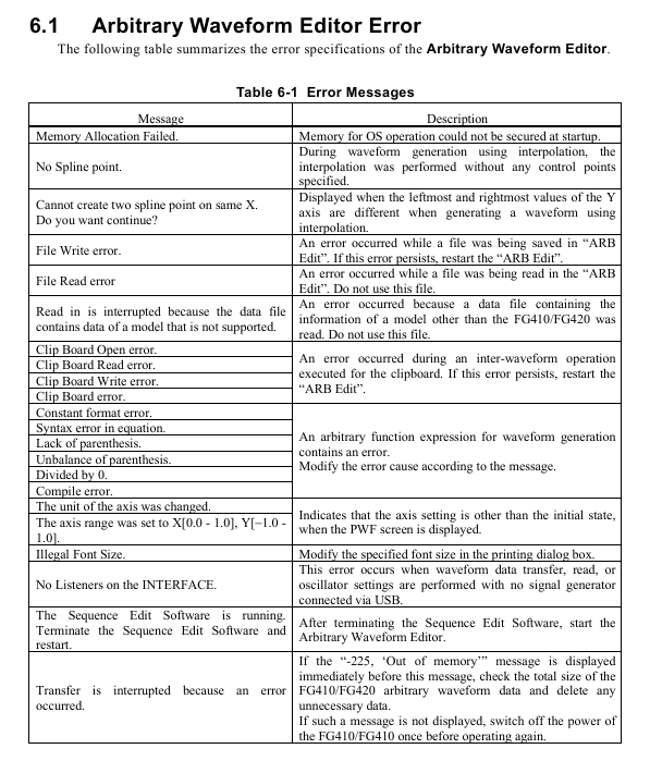
The possible errors and countermeasures during software operation are as follows:
Solution to Error Information Causes
Memory Allocation Failed. Insufficient memory allocation during startup. Close other applications and restart software; If it occurs frequently, check if the system memory is sufficient
No Spline point interpolation generates waveforms without setting control points. Add at least 2 control points before performing interpolation
File Read/Write error: File read/write failure (e.g. path does not exist, insufficient permissions). Check if the save path exists and run the software with administrator privileges; Damaged files need to be recreated
No listeners on the FACE USB not connected to the instrument or driver not installed. Check the USB connection, reinstall the NI-VISA driver, and restart the instrument and software
Transfer is interrupted. If the instrument malfunctions (such as insufficient memory) and prompts "Out of memory", delete the useless waveforms in the instrument; Otherwise, restart the instrument and retry
Illegal Font Size When printing, adjust the font size in the print settings (if it is set to 12) to avoid exceeding the range
2. Software maintenance
CD maintenance: Store in a cool and dry place, avoid direct sunlight and dust; Wipe with a soft dry cloth when dirty, and prohibit the use of solvents such as benzene; Use a marker pen to write on the label surface to avoid scratches from hard objects.
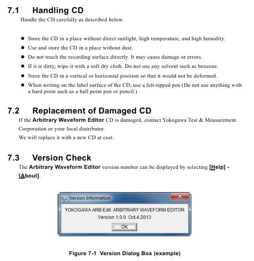
Version check: Check the software version (such as Version 1.0.0) through "Help → About" to confirm if it is the latest version. If an update is needed, contact the Yokogawa distributor.
CD damage replacement: If the installation CD is damaged, you can contact Yokogawa to purchase a new CD (for a fee) and provide the product model and purchase certificate.
- OMRON
- ABB
- General Electric
- EMERSON
- Honeywell
- HIMA
- ALSTOM
- Rolls-Royce
- MOTOROLA
- Rockwell
- Siemens
- Woodward
- YOKOGAWA
- FOXBORO
- KOLLMORGEN
- MOOG
- KB
- YAMAHA
- BENDER
- TEKTRONIX
- Westinghouse
- AMAT
- AB
- XYCOM
- Yaskawa
- B&R
- Schneider
- KONGSBERG
- NI
- WATLOW
- ProSoft
- SEW
- ADVANCED
- Reliance
- TRICONEX
- METSO
- MAN
- Advantest
- STUDER
- DANAHER MOTION
- Bently
- Galil
- EATON
- MOLEX
- DEIF
- B&W
- ZYGO
- Aerotech
- DANFOSS
- Beijer
- Moxa
- Rexroth
- Johnson
- WAGO
- TOSHIBA
- BMCM
- SMC
- HITACHI
- HIRSCHMANN
- Application field
- XP POWER
- CTI
- TRICON
- STOBER
- Thinklogical
- Horner Automation
- Meggitt
- Fanuc
- Baldor
- SHINKAWA
- Other Brands
- UniOP
- KUKA
- Iba
- Beckhoff
-
 Basler D90 96801 100 PCB Card
 -
 Basler XR2002F Voltage Regulator (110 VAC, 48-480 Hz)
 -
 Basler SR8A-2B14B3A Regulator
 -
 Basler 9561500100 Module
 -
 Basler DECS-400 BE1-11 System
 -
 Basler DECS-100-B15 Excitation Control
 -
 Basler SCP 210 Frequency Controller
 -
 Basler SR4A-2B15B3A Static Voltage Regulator
 -
 Basler BE1-32R Power Relay
 -
 Basler PIA2400-17GM Power Interface Adapter
 -
 Basler MVC 232 Manual Voltage Control Module
 -
 Basler SSR 32-12 Static Voltage Regulator
 -
 Basler 5MW AVR Generator Voltage Regulator
 -
 Basler VR63-4B Voltage Regulator
 -
 Basler DECS-100-A05 AVR for Engine Generator
 -
 Basler DECS-100-B15 Automatic Voltage Regulator
 -
 Basler BE1-32R Directional Power Relay
 -
 Basler BE1-87B Differential Relay
 -
 Basler UFOV 260A Protective Module
 -
 Basler 9-2614-02-100 PCB Rev M
 -
Basler DECS-100-B15 Digital AVR
-
 Basler 9284900103 PS DECS-400N
 -
 Basler D4N3H1U Intertie Protection
 -
 Basler DECS-100-B15 A15 AVR
 -
 Basler KR4F Voltage Regulator
 -
 Basler BE26434 T14 Transformer
 -
 Basler SR8A-2B15B3A Regulator
 -
 Westinghouse 774B472A12 AR Relay
 -
Basler DECS-100-B15 AVR
-
Basler XR2002F Regulator 110V
-
Basler SR125-E Static Regulator
-
 Basler SSR 125-12 Regulator
 -
 Basler MOC2599 Motor Pot
 -
 Basler BE1-DFPR Feeder Relay
 -
 Basler CBS 305 Current Boost
 -
 Basler BE1-25 AutoSync
 -
 Basler MVC 300 Voltage Control
 -
 Basler BE3-25A AutoSync
 -
 Basler KR7FF Static Regulator
 -
 Basler 90-49000-100 Regulator
 -
 Basler 880 kVA Dry Type Transformer Specs
 -
 Basler Electric BE1-25 Sync-Check Relay Specs
 -
 Basler SSR 125-12 Voltage Regulator Specs
 -
 Basler Electric BE1-851 Overcurrent Relay Review
 -
Basler Electric 149D930G02 Control Sub-Assembly
-
 Basler Electric BE1-81O/UT Frequency Relay Specs
 -
 Basler Electric BE1-51/27C Overcurrent Relay
 -
 Basler Electric 149D956G02 Industrial Component
 -
Basler Electric BE1-51A Overcurrent Relay Specs
-
 Basler Electric BE1-40Q Loss of Excitation Relay
 -
 Basler DECS-200 Excitation Control System
 -
 Basler DECS-200 Voltage Regulator 56-277V AC / 125V DC
 -
Basler BE1-87T Transformer Differential Relay
-
 Basler RDP-110-S1 Protection Relay
 -
 Basler BE1-700V Digital Protective Relay
 -
 Basler BE1-951 Overcurrent Protection System
 -
 Basler DECS-300 Digital Excitation Control
 -
 Basler DECS-200 Digital Excitation Control
 -
 Basler DECS-200-1C Excitation Control System
 -
Basler DECS-200-1L Digital Excitation Control
-
 Basler Electric BE1-GPS Generator Protection System
 -
Basler Electric DECS-200-1C Digital Excitation Controller
-
 Basler Electric DECS125-15 Excitation Control with Power Module
 -
 Basler Electric BE1-87G Differential Relay
 -
 Basler Electric BE1-11 Protection System I5A3M2P2N0EA00
 -
Basler Electric DECS-200-1C Excitation Control System
-
Basler Electric BE1-11g Generator Protection Relay
-
Basler Electric DECS 125-15-B2C1 V2.0.9 Excitation Control
-
 Basler Electric BE1-81O/UT3ED1JA7N2F Frequency Relay
 -
Basler Electric BE1-81O/UT3EE1YB7N1F Frequency Relay
-
 Basler Electric DECS-200-1L Digital Excitation Control System
 -
Basler DECS125-15-B2C1 Excitation Control
-
 Basler 9507900205 SSR Retrofit Voltage Regulator
 -
 Basler BE2000E Digital Voltage Regulator
 -
 Basler BE1-GPS Generator Protection System
 -
Basler DECS-250-CN1CN1N Digital Excitation Control
-
 Basler DGC-2020 Genset Controller
 -
 Basler BE1-81O UT3ED1LA7N0F Frequency Relay (Variant)
 -
 Basler BE1-81O UT3EE1YA9S0F Frequency Relay (Variant)
 -
Basler BE1-81O Over/Under Frequency Relay
-
Basler DECS125-15 Digital Excitation Control
-
Basler Electric BE1-951 Overcurrent Protection System
-
 Basler Electric BE1-700V Digital Protective Relay
 -
 Basler Electric APR63-5 Automatic Voltage Regulator
 -
Basler Electric BE1-851 Overcurrent Protection System
-
Basler Electric DECS-250-LN1SN1N Excitation Control
-
 Basler Electric BE1-87T Transformer Differential Relay
 -
Basler Electric DECS-200-1L Excitation Control System
-
 Basler Electric 9310300100 DECS-300 Excitation Control
 -
 Basler Electric SSE-N 125-4.5KW Shunt Exciter Regulator
 -
 Basler Electric DGC-2020HD-5NS1DNSBA Genset Controller
 -
Basler Electric BE1-81-O/UT3EE1JB7N1F Frequency Relay
-
Basler Electric BE1-81T1EE1WA0N1F Frequency Relay
-
 Basler Electric BE1-25M1EA6PN5R1F Sync-Check Relay
 -
 Basler Electric BE1-GPS Generator Protection System
 -
Basler Electric DECS-250-LN1SN1N Excitation Control Rev V
-
 Basler Electric DECS-250-CN2CN1N Excitation Control
 -
Basler Electric BE1-50/51B-207 Overcurrent Relay
-
Basler Electric DECS-300-C0N0 Excitation Control System
-
Basler Electric DECS-200 Digital Excitation Control System
-
Basler Electric DECS-250-LN1CN1N Excitation Unit
-
Basler Electric DECS-250 LN2SA1D Excitation Unit Specs
-
Basler Electric BE1-87T Transformer Relay Review
-
Basler Electric BE1-11 Protection System
-
Basler Electric BE1-GPS100-E4N1H1N Protection System
-
 Allen-Bradley 442G-MABH-R Safety Module
 -
 Beckhoff CX1030-0111 PLC Assembly Profile
 -
 FANUC IC693CPU364 PLC Module
 -
 Orange Denmark Type 200816 220 PLC Specs
 -
 OMRON C200H-SNT31 Sysmac PLC Module
 -
 Allen Bradley 20AB022A3AYNANC0 PowerFlex 70
 -
 OMRON C200HW-PCU01 Position Control Unit
 -
 ABB AO845A-eA Analog Output Module
 -
 OMRON CJ1M-CPU22 CPU Unit
 -
 Allen Bradley 100-E265ED11 Contactor
 -
 Honeywell 51304511-100 Interface Module
 -
 SOLEXY BXF3S0101N0018 Gateway Module
 -
 OMRON CJ2H-CPU65 CPU Unit
 -
 Automation Direct GS2-45P0 AC Drive
 -
 M68-2000 2-Axis Motion CNC Controller
 -
 OMRON CJ1M-CPU11 V3.0 PLC CPU Unit
 -
 OMRON CJ1W-NC413 4-Axis Positioning Controller
 -
 OMRON 3G2A3-PRO16 Programming Console HMI
 -
 Siemens 3VT8440-2AA04-2GA2 Molded Case Circuit Breaker
 -
 Siemens 3RT5045 Contactor Series
 -
 OMRON C200HS-CPU01-E SYSMAC PLC Controller
 -
 OMRON C500-NC103-E Positioning Control Unit
 -
 OMRON CJ1W-TC001 Temperature Control Unit


