
SIEMENS G120 CU240BE-2 frequency converter
SIEMENS G120 CU240BE-2 frequency converter
Detailed analysis of parameter system
(1) Basic rules for parameters (supplementary configuration logic)
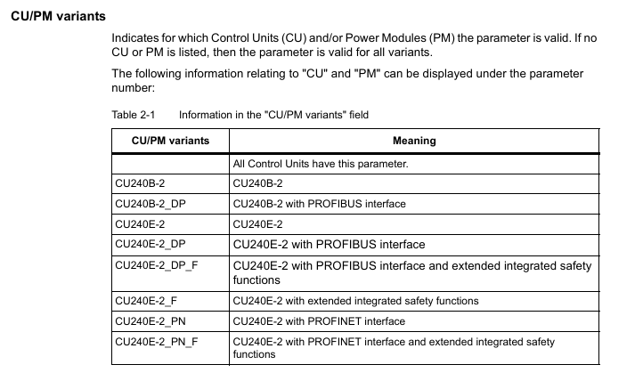
Parameter number and type
Number format: Read and write parameters starting with "p" (such as p0003), read-only parameters starting with "r" (such as r0002, displaying the running status of the driver);
Index identifier: with [0... n] indicating multiple index parameters (such as p0304 [0... n], supporting storage of multiple motor parameters);
Bit field identifier: with. 0... n represents bit parameters (such as r0046.0, corresponding to the switch status of specific functions).
Parameter access and modification rules
Access level control: Set through P0003, Level 3 (expert level) includes 1-2 levels of functionality, and Level 4 (service level) requires a password (p3950) to unlock;
Modification effective conditions: Some parameter annotations "C (x)" indicate that they can only be modified in debugging mode (p0010=x), "U" indicates that they can be modified during operation, "T" indicates that they can be modified in the ready state, and some parameter modifications require restarting the frequency converter to take effect;
The impact of associated parameters: The "Linked parameterization" feature automatically synchronizes the modification of associated parameters when modifying some parameters (such as p0922 PROFIBUS telegram), and the impact range needs to be confirmed in advance.
(2) Detailed analysis of core parameter module
1. Basic configuration parameters (p0000-p0999)
Parameter Number Parameter Name Core Function Value Range Default Values Key Explanation
The parameter range that can be viewed/modified in the access level control of P0003 is 3 (expert), 4 (service), and 3/4. The password p3950 is required for level 4, and only authorized service personnel can operate it
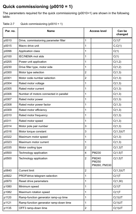
P0010 Debugging parameter filter filters visible parameters at different debugging stages 0-95 1 0=ready, 1=fast debugging, 3=motor debugging, 15=dataset configuration, 30=parameter reset, 95=safety integration debugging
P0015 Driver Unit Macro Run Preset Macro File, Quickly Configure Typical Application Scenarios 0-999999 7 (CU240B-2)/12 (CU240E-2) After Execution, Parameter Lock, R3996=0 is Required to Modify Again
P0096 Application class switching control view (adapted to different application scenarios) 0=Expert, 1=Standard drive control, 2=Dynamic drive control 0 1=Suitable for standard loads such as pumps/fans, 2=Suitable for high dynamic response loads (such as machine tools)
P0100 Standard Selection (IEC/NEMA) Switching Motor Parameter Unit System 0=IEC, 1=NEMA, 2=NEMA+SI 0 0=Power Unit kW, Frequency 50Hz; 1=Power Unit hp, Frequency 60Hz
P0170 Command Dataset Quantity (CDS) Configuration: The number of storable command datasets is 2-4. 2 Supports quick switching of different control commands (such as manual/automatic frequency source switching)
P0180 Driver Dataset Quantity (DDS) Configuration: The number of storable driver datasets ranges from 1 to 4, and supports fast switching of different motor or load parameters (such as multiple motors sharing a frequency converter)
2. Motor parameters (p0300-p0399)
The core is used to match the motor nameplate data, which directly affects the control accuracy and protection function, and is a key debugging step:
Parameter Number Parameter Name Core Function Value Range Default Values Key Explanation
P0300 Motor type selection definition: Motor type 0=no motor, 1=induction motor, 2=synchronous motor, etc. After selecting 0, the corresponding motor parameters will be automatically filtered. If the synchronous motor does not display the exclusive parameters of the induction motor
P0301 motor code number: Select motor model 0-65535 from the built-in motor parameter list. 0=manually input parameters,>0=load preset parameters from Siemens motor database
The rated voltage input on the motor nameplate of P0304 motor is 0-20000 Vrms, which needs to be matched with the supply voltage. When connected in a star/delta configuration, it needs to be adjusted accordingly (such as the delta connection voltage being √ 3 times that of the star configuration)
The rated current input on the motor nameplate of P0305 motor is 0.00-10000 Arms 0.00, which directly affects the overcurrent protection threshold (p2100). Setting the wrong value may cause protection to trigger incorrectly or the motor to burn out
P0307 motor rated power input: The rated power on the motor nameplate is 0.00-100000 kW. The IEC standard unit is kW, and the NEMA standard unit is hp (when P0100=1)
P0310 motor rated frequency input: The rated frequency on the motor nameplate is 0.00-650.00 Hz. The default is 50Hz (IEC)/60Hz (NEMA), which affects the speed calculation (n=60f/p, p is the number of pole pairs)
The rated speed input on the nameplate of the P0311 motor ranges from 0.0 to 210000 rpm. 0.0 is used as the reference value for speed closed-loop control and, together with P0310, determines the number of motor poles (r0313)
P0340 automatically calculates parameters based on nameplate data to automatically calculate motor equivalent circuit parameters and control parameters 0-50 1=complete calculation, 2=motor parameter calculation, 3=closed-loop control parameter calculation, 4=controller parameter calculation, 5=threshold calculation
3. Control mode and speed parameters (p1000-p1999)
Parameter Number Parameter Name Core Function Value Range Default Values Key Explanation
P1000 frequency setting source selection frequency converter output frequency control mode 0-10 2 0=none, 1=terminal, 2=analog, 5=communication, 7=PID, 10=process controller
P1080 Minimum output frequency limit: The minimum output frequency of the frequency converter is 0.00-600.00 Hz to prevent overload during low-speed operation of the motor (such as pump loads to avoid idling)
P1082 Maximum output frequency limit: The maximum output frequency of the frequency converter should not exceed 1.2 times the rated frequency of the motor (p0310), from 0.00-600.00 Hz to 50.00/60.00 Hz, to avoid motor overspeed damage
P1120 Acceleration time from 0 to maximum frequency rise time 0.01-6500.0 s 10.0 The greater the load inertia, the longer the acceleration time needs to be to prevent overcurrent tripping
The descent time from maximum frequency to 0 for p1121 deceleration time is 0.01-6500.0 s 10.0, which needs to be matched with the load braking demand. For large inertia loads, the deceleration time needs to be extended or braking resistors need to be configured
P1300 control mode selection: The core control algorithm of the frequency converter is 0-22. 20=V/f control, 20=vector control (without encoder), 21=vector control (with encoder), 22=torque control
P1900 motor recognition automatically identifies motor equivalent circuit parameters, optimizes control accuracy 0-3 20=disabled, 1=static recognition, 2=dynamic recognition (motor idling required), 3=precise recognition
4. Fault protection parameters (p2100-p2299)
Parameter Number Parameter Name Core Function Value Range Default Values Key Explanation
P2100 overcurrent protection threshold setting: The upper limit of overcurrent protection current is 1.0-2.0 times the rated current, and 1.5 times the rated current. If the threshold is exceeded, the frequency converter will immediately trip to avoid damage to the power module
P2175 overvoltage protection threshold setting DC bus overvoltage protection threshold 1.0-1.3 times rated voltage 1.15 times suitable for voltage fluctuation scenarios in the power grid. If the threshold is too high, it may cause capacitor damage
P2176 undervoltage protection threshold setting DC bus undervoltage protection threshold 0.7-0.9 times rated voltage 0.85 times lower than the threshold, the frequency converter will operate at reduced capacity or trip to prevent insufficient motor torque
P2200 motor overheat protection enable/disable motor overheat protection function 0=disable, 1=enable 1 Based on motor temperature model (p0612) or temperature sensor signal, rated or tripped when overheated
P2260 torque limit motor output torque 0.0-200.0% 150.0% to prevent motor damage caused by load overload, which needs to be adjusted according to the rated torque of the load
5. Communication parameters (p2000-p2099)
Parameter Number Parameter Name Core Function Value Range Default Values Key Explanation
P2010 communication address (PROFIBUS/Modbus) setting: The address 1-126 of the frequency converter in the communication network should be consistent with the configuration of the upper computer (PLC/HMI) to avoid address conflicts
P2023 Communication Baud Rate (Modbus) Set the transmission rate of Modbus communication to 9600/19200/38400/115200 bps. The higher the baud rate, the faster the transmission speed, but it is limited by the communication distance (such as 115200bps, recommended distance<10m)
P2080 PROFIdrive status word mapping configuration for PROFIBUS/PROFINET status word signal source 0-65535 0 defines the operating status signals (such as ready, fault, running) fed back by the frequency converter to the PLC
P2081 PROFIdrive control word mapping configuration PROFIBUS/PROFINET control word signal source 0-65535 0 defines the control commands sent by PLC to the frequency converter (such as start stop, frequency setting, fault reset)
6. Input/Output (I/O) Parameters (p0700-p0799)
Parameter Number Parameter Name Core Function Value Range Default Values Key Explanation
P0700 Definition of Digital Input Function Allocation: Functions of Digital Input Terminals (DI) 0-99 2 0=No Function, 1=ON/OFF 1, 2=ON/OFF 2 (Emergency Stop), 3=ON/OFF 3 (Quick Stop)
P0730 Digital Output Function Allocation (DO0) defines the function of the digital output terminal (DO0) from 0 to 99. 52.0 0=no function, 52.0=ready state, 52.3=fault state, 52.7=alarm state
P0756 Analog Input Type (AI0/AI1) Set the signal type of the analog input terminal to 0-8 4 0=0-10V voltage input, 2=0-20mA current input, 3=4-20mA current input, 4=-10V~+10V bipolar voltage
P0771 Analog Output Function Allocation (AO0) defines the signal source 0-99 of the analog output terminal (AO0). 21.0 0 0=no function, 21.0=output frequency, 27.0=output current, 28.0=output voltage
(3) Read only parameters and status monitoring (r series)
The manual provides a detailed list of R-series read-only parameters for real-time monitoring of equipment operation status. The core parameters are as follows:
R0002: Driver operating status (e.g. 0=everything is normal, 10=need to activate set value, 35=need initial debugging);
R0021: Actual speed (smoothed), in rpm, reflecting the real-time speed of the motor;
R0025: Output voltage (smoothed), in Vrms, monitor the output voltage of the frequency converter;
R0027: Output current (smoothed), in Arms, to determine if the motor is overloaded;
R0031: Actual torque (smoothed), in Nm, reflecting the magnitude of the load torque;
R0052: Status word 1, displaying device ready, running, fault and other statuses through bit fields (such as bit0=ready, bit3=fault);
R0207: Rated current of power unit, reflecting the rated capacity of the inverter hardware;
R2135: Fault/alarm status word, records current or historical fault codes.
(4) Functional diagrams and logical associations
Chapter 3 of the manual provides detailed 590 page functional diagrams, covering:
Input/output terminal wiring logic (such as signal flow direction of DI/DO/AI/AO);
PROFIdrive communication protocol interaction logic (PROFIBUS/PROFINET data frame structure);
Control mode logic (such as speed closed-loop and torque closed-loop processes of vector control);
Fault protection logic (such as detection and tripping processes for overcurrent and overvoltage);
BICO parameter interconnection logic (such as the signal correlation between BI parameters and BO parameters).
Functional diagrams use standardized symbols to label parameter numbers and signal flow directions, helping technicians understand the underlying logic of parameter configuration. For example, the "speed control closed-loop" diagram clarifies the complete process of comparing r0021 (actual speed) and p1070 (speed set value), PID regulation, and output drive.
(5) Troubleshooting and Alarm Handling (Chapter 4)
Fault/alarm classification
Faults: The equipment cannot operate normally and needs to be manually reset after troubleshooting (such as F30002=DC bus overvoltage);
Alarm: The device can still operate but there are abnormalities that need attention (such as A07012=motor overheating warning).
Troubleshooting process
Step 1: Read the fault code through r2135 or the operation panel;
Step 2: Search the manual for the corresponding cause of the fault code (such as F30005=power unit I2t overload);
Step 3: Check according to the manual recommendations (such as checking if the load is overloaded and if the heat dissipation is good);
Step 4: Modify the corresponding parameters (such as adjusting the p2260 torque limit) or reset after fixing hardware faults.
Common faults and troubleshooting examples
F30002 (DC bus overvoltage): The reason may be that the grid voltage is too high and the deceleration time is too short; The processing method is to adjust the overvoltage threshold of p2175, extend the deceleration time of p1121, and configure the braking resistor;
F30005 (power unit I2t overload): The reason may be continuous overload of the load or a malfunction of the cooling fan; The processing method is to reduce the load, check the fan, and adjust the p0290 overload response strategy;
F07011 (motor overheating): The possible reasons may be excessive motor load or temperature sensor malfunction; The processing method is to reduce the rated operation, check the sensor, and adjust the P0605 overheating threshold.
Example of Key Application Scenario Parameter Configuration
Scenario 1: Pump/Fan Load (Standard Drive Control, p0096=1)
Basic configuration: p0010=1 (quick debugging) → p0300=1 (induction motor) → Input p0304/p0305/p0307/p0310 (motor nameplate data);
Control mode: p1000=2 (analog frequency source) → p1300=0 (V/f control);
Protection configuration: p2200=1 (motor overheating protection) → p2260=110% (torque limit);
Operating parameters: p1080=1.0Hz (minimum frequency anti slip) → p1120=30s (extended acceleration time waterproof hammer) → p1121=30s (extended deceleration time);
Confirm save: p3900=1 (complete quick debugging) → Parameters automatically take effect.
Scenario 2: Machine tool spindle load (dynamic drive control, p0096=2)
Basic configuration: p0010=1 → p0300=1 → Input motor nameplate data → p1900=2 (dynamic motor recognition);
Control mode: p1000=5 (communication frequency source) → p1300=20 (vector control without encoder);
Dynamic parameters: p1400=3.0 (PID proportional coefficient) → p1401=0.1 (PID integration time) → optimized dynamic response;
Protection configuration: p2100=1.8 (overcurrent threshold) → p2260=150% (torque limit) → p2175=1.2 (overvoltage threshold);
Communication configuration: p2010=5 (communication address) → p2080=1 (status word mapping) → p2081=1 (control word mapping);
Confirm save: p3900=2 → Restart the frequency converter to take effect.
Precautions and Risk Warning for Use
Before parameter configuration:
Confirm the control unit model and firmware version (r0018) to ensure parameter compatibility;
Disconnect the motor load or ensure that the load is in a safe state to avoid accidental operation of the equipment during debugging;
Backup the original parameters (p0971=1) for easy recovery in case of configuration errors.
In parameter configuration:
Strictly input the parameters p0300-p0311 according to the motor nameplate, incorrect settings may cause the motor to burn out;
Parameters related to safety functions (such as p0930 safety integration parameters) need to be configured by authorized personnel, and failure to comply with safety standards may result in personal injury;
The communication parameters must be consistent with the upper computer, otherwise a communication connection cannot be established.
After parameter configuration:
Conduct no-load testing (no-load operation), monitor parameters such as r0021/r0027/r0031, and confirm that the equipment is running normally;
Gradually load the load, observe whether the protection function is triggered, and verify the rationality of the parameters;
Record key parameters (such as motor data, communication address) for easy maintenance in the future.
Common risk avoidance:
Avoid modifying the rated parameters of the motor (p0304, etc.) during operation, which may cause instantaneous overload tripping;
Do not set p0290 (overload response) to 1 (trip directly without derating) unless there is no possibility of overload on the load;
Incorrect setting of analog input type (voltage/current) (p0756) can result in abnormal frequency setting.
- OMRON
- ABB
- General Electric
- EMERSON
- Honeywell
- HIMA
- ALSTOM
- Rolls-Royce
- MOTOROLA
- Rockwell
- Siemens
- Woodward
- YOKOGAWA
- FOXBORO
- KOLLMORGEN
- MOOG
- KB
- YAMAHA
- BENDER
- TEKTRONIX
- Westinghouse
- AMAT
- AB
- XYCOM
- Yaskawa
- B&R
- Schneider
- KONGSBERG
- NI
- WATLOW
- ProSoft
- SEW
- ADVANCED
- Reliance
- TRICONEX
- METSO
- MAN
- Advantest
- STUDER
- DANAHER MOTION
- Bently
- Galil
- EATON
- MOLEX
- DEIF
- B&W
- ZYGO
- Aerotech
- DANFOSS
- Beijer
- Moxa
- Rexroth
- Johnson
- WAGO
- TOSHIBA
- BMCM
- SMC
- HITACHI
- HIRSCHMANN
- Application field
- XP POWER
- CTI
- TRICON
- STOBER
- Thinklogical
- Horner Automation
- Meggitt
- Fanuc
- Baldor
- SHINKAWA
- Other Brands
- UniOP
- KUKA
- Iba
- Beckhoff
- ADLINK
-
 Basler Electric BE1-700 Digital Protective Relay
 -
 Basler Electric SR8A-2B01B3A Static Voltage Regulator
 -
 Basler Electric SR4A-2B01B3E Static Voltage Regulator
 -
 Basler Electric 9017709102 PC Board
 -
Basler Electric SR4A-2B01B3A Static Voltage Regulator
-
 Basler Electric PRS-250 Veri-Sync Relay
 -
 Basler Electric 9066800102 Excitation Support System
 -
 Basler Electric BE1-87G Generator Differential Relay 9 1708 18 100
 -
 Basler Electric 36T865-2 BE03752001 Power Supply
 -
 Basler Electric M-300 149D940G02 Power Supply
 -
 Basler Electric ACA2040-25GM 4Mp 25Fps Area Scan Camera
 -
 Basler BE1-87G-S1A-A1C-A0N0 Differential Relay
 -
 Basler SR8A-2B06B3E Static Regulator SR8A2B06B3E
 -
 Basler SCP-210 Frequency Controller 9095400100
 -
 Basler BE1-59-A3E-A1J-N1N3F Overvoltage Relay BE159A3EA1JN1N3F
 -
 Basler 9 2011 11 100 Bracket Mounted Terminal Unit
 -
Basler 9 1606 00 101 Voltage Regulator
-
 Basler CBS-377 Current Boost System 9109600102
 -
 Basler 8650C72 Exciter Control Module PCB Rev 5
 -
 Basler C2EE1PA0N1F BE1-32R Reverse Power Relay
 -
 ADLINK HPCI-14S12U - Industrial Control Backplane 12PCI Backplane PCI-14S Passive Backplane
 -
-0010.png) ADLINK PCIe-GIE74C - image acquisition card 4-CH GigE Vision PoE+ Frame Grabber
ADLINK PCIe-GIE74C - image acquisition card 4-CH GigE Vision PoE+ Frame Grabber -
-0010_1.png) ADLINK PCI-8164 - control card 4-Axis Advanced Motion Controller Board
ADLINK PCI-8164 - control card 4-Axis Advanced Motion Controller Board -
 ADLINK PCIe-U304 - 4 Port USB3 PCIe Frame Grabbers USB Screw Hole Card
 -
 ADLINK PCI-9112 - Multi-Function Data Acquisition Card DAQ Card
 -
 ADLINK PCI-7432 - 51-12013-0A50 4-CH Isolated Numérique I/O PCI Cartes Digital I/O Card
 -
 ADLINK PCA-6106P3-0C1 REV.C1 - backplane 6-Slot Passive Backplane Board
 -
 ADLINK PCI-7224 - 24-CH Opto-Isolated Digital I/O PCI Board
 -
 ADLINK CPCI-7433R(G) - Digital Input Board Rear I/O CompactPCI Card
 -
 ADLINK EBP-13E4 - 51-46703-0A30 Industrial PC Backplane Passive Backplane
 -
 ADLINK PCIE-HDV62 - Image acquisition card High Definition Video Frame Grabber
 -
 ADLINK EBP-13E4 - 51-46703-0A30 Industrial Backplane Board Passive Backplane
 -
 ADLINK 90111-B1 / CPCI-6770 - PCB CPU MODULE CompactPCI Single Board Computer
 -
 ADLINK PCI-7248 - DATA ACQUISITION PCI CARD 48-CH Parallel Digital I/O Board
 -
 ADLINK PCI-7230 - 51-12003-0a50 board PCI7230 32-CH Isolated Digital I/O Card
 -
 ADLINK PCI2A000CB - 51-20000-0B30 Multi-Function DAQ Card Baseboard
 -
 ADLINK PCI-8134-005 - 4-Axis Motion Controller Card
 -
 ADLINK PCI-7224 - 24-CH Opto-Isolated Digital I/O PCI Card
 -
 ADLINK PCI-7434 - 64-CH Isolated Digital Output Card
 -
 ADLINK PCI-8132 - motion control card 2-Axis Servo & Stepper Controller
 -
 ADLINK PCI-8134 - Motion Controller PCI Card 4-Axis Controller Board
 -
 ADLINK PCI-8164 - Motion Control Card 51-12406-0A40 4-Axis Controller
 -
 ADLINK 51-12001-0C20 - Circuit Board Data Acquisition Interface Module Hardware
 -
 ADLINK NuPR0-840 - industrial control motherboard Full-Size PICMG CPU Board
 -
 ADLINK PCI-7444 - 51-12023-0A10 card 128-CH Isolated Digital Output Board
 -
 ADLINK PCI-1612B - data acquisition card 4-Port RS-232/422/485 Serial Communication Card
 -
 ADLINK PCI-6208V 009 - 8/16-CH 16-Bit Analog Output Cards PCB-I-E-482=6BX3
 -
 ADLINK NUPRO-935A/LV - industrial control motherboard Full-Size PICMG SBC Board
 -
 ADLINK PCI-9114DG - Multi-Function DAQ Card Data Acquisition PCI Card
 -
 ADLINK ACL-7130 - Data acquisition card Isolated Digital I/O Board
 -
 ADLINK ABX-6300D-4E1-BP - board ABX6300D4E1BP Video Interface Expansion Card
 -
 ADLINK CPCI-6940 - CPCI-6940/D1539/M16-0(EA)-000E 6U CompactPCI Processor Board
 -
 ADLINK NuPRO-760 - industrial control motherboard Half-Size PICMG SBC CPU Board
 -
 ADLINK IMB-M42H (G)-0020 - industrial control motherboard LGA1155 Micro-ATX Mainboard
 -
 ADLINK RTV-24 / PCI-MP4S - 51-12519-1C30 4-Channel Real Time Video Capture Board
 -
 ADLINK PCI-8134 - 4-Axis Servo & Stepper Motion Controller Card
 -
 ADLINK MXC-6101D - V.PC000.002.ST.00 Box PC Configurable Embedded Computer
 -
.png) ADLINK PCI-8134A - 51-12421-0A10 Motion Control Card 4-Axis Controller Card
ADLINK PCI-8134A - 51-12421-0A10 Motion Control Card 4-Axis Controller Card -
 ADLINK DIN-100S / DIN-100SA1 - Technology SCSI-II TB 100-PIN Terminal Block Board
 -
.png) ADLINK DIN-812M001 / DIN812M001 - 51-14034-0A1 51140340A1 Terminal Module Breakout Interface
ADLINK DIN-812M001 / DIN812M001 - 51-14034-0A1 51140340A1 Terminal Module Breakout Interface -
_1.png) ADLINK PCI-8164 - Servo motion control 4-Axis Advanced Controller Card
ADLINK PCI-8164 - Servo motion control 4-Axis Advanced Controller Card -
 ADLINK PCIe-GIE64 - Acquisition card GigE Vision PoE+ Frame Grabber
 -
 ADLINK M-302 - Industrial control motherboard ATX PC Board Mainboard
 -
 ADLINK PCI-8134 - Motion Controller PCI Card 4-Axis Controller Board
 -
 ADLINK PCI-RTV24 - Image capture card Analog Video Frame Grabber
 -
 ADLINK PCI-8102 - Motion control card 2-Axis Servo & Stepper Controller Board
 -
 ADLINK PCI-9112 REV.B1 - Card Multi-Function Data Acquisition Card
 -
 ADLINK HSI-DI32-M-N / HSL-TB32-M-DIN - Discrete I/O MODULE Distributed Automation Module System
 -
 ADLINK PCI-7296 - IO card REV.A3 96-CH Parallel Digital I/O Card
 -
-0020.png) ADLINK DIN-814P-A4 / 814Y - terminal board Motion Control Interface Block
ADLINK DIN-814P-A4 / 814Y - terminal board Motion Control Interface Block -
 ADLINK DIN-814P-A4 - 51-14056-0A10 PCB-I-E-2736=ZA01 Screw Terminal Board Breakout
 -
 ADLINK M-322 - motherboard Industrial Control Computer Mainboard
 -
 ADLINK NUPRO-406 REV:B1 - industrial control motherboard Full-Size PICMG CPU Board
 -
 ADLINK AMP-204C - card DSP-Based 4-Axis Advanced Pulse-Train Controller
 -
 ADLINK HPCI14S REV.B1 - industrial computer baseboard 14-Slot Passive Backplane
 -
 ADLINK PCI-7250 - 8-CH Relay Output & 8-CH Isolated DI PCI Card
 -
 ADLINK EBP-13E2 - baseplate Passive Backplane Industrial Computer Chassis Board
 -
 ADLINK LPCI-3488A - PCI-GPIB card 51-12801-0A30 acquisition card IEEE-488 Interface Board
 -
 ADLINK PCI-6216V-GL - 51-12201-0C30 16-CH 16-Bit Voltage Analog Output Card
 -
 ADLINK ACL-8454 - 16-CH Isolated Digital I/O & 4-CH Counter Card
 -
 ADLINK HPCI-9S7U - backplane Passive Backplane Compatible with NuPRO-A301 852 841 842
 -
 ADLINK DAQ-2010-007 - Simultaneous-Sampling Multi-Function Data Acquisition Card
 -
 ADLINK MP-C154 - 51-64205-0A10 Motion Control Card 4-Axis Controller Board
 -
 ADLINK MXE-202/mSSD16B/WiFi-BT - Matrix Rugged I/O Platform Embedded Fanless Computer
 -
 ADLINK CM-920-R-17 - PC/104-Plus Single Board Computer Module Intel Celeron M
 -
 ADLINK PCI-7250 NSMP - 8-CH Relay Output & 8-CH Isolated DI Card
 -
 ADLINK PCI-8164 - 4-Axis Motion Controller PCI Card W/ Cable and Breakout Box
 -
 ADLINK EMX-100 - Ethernet-based 4-axis Motion Controllers Distributed Motion Module
 -
.png) ADLINK PCI-8134A - Press control card 4-Axis Motion Controller Board
ADLINK PCI-8134A - Press control card 4-Axis Motion Controller Board -
 ADLINK M-845EG REV:3.2 - industrial motherboard Pentium 4 Socket 478 Micro-ATX
 -
 ADLINK PCI-9114A Rev A2 DG - card High-Resolution Multi-Function Data Acquisition Board
 -
 ADLINK IEC-915GV - REV 1.1 Industrial motherboard Socket 478 CPU Board
 -
 ADLINK PCI-9111DG(G) - Data Acquisition Card Multi-Function DAQ Card
 -
 ADLINK HPCI-15S10 REV:B2 - Industrial computer base plate Passive Backplane Board
 -
 ADLINK NuPR0-840 / NuPR0-840DV - industrial control motherboard Full-size PICMG CPU Board
 -
 ADLINK RTV-24 / PCI-MP4S - 51-12519-1C30 4-Channel Real Time Video Capture Board
 -
 ADLINK NUPRO-780 - industrial control motherboard Pentium III Single Board Computer
 -
 ADLINK PCI-7296 - 0050 card 96-CH Opto-Isolated Parallel DIO Card Set
 -
-0040.png) ADLINK NUPRO-780 - industrial control motherboard PICMG Full-Size SBC
ADLINK NUPRO-780 - industrial control motherboard PICMG Full-Size SBC -
 ADLINK PCI-7248 - 51-12006-0A3 002 Pci 7248 48-CH Parallel Digital I/O Card
 -
 ADLINK PCI-7230 - 32-CH Isolated Digital I/O Card
 -
 ADLINK AMP-204C - motion control card 4-Axis Advanced Controller Board
 -
.png) ADLINK PCI-1714UL - Card Ultra High-Speed 4-CH Simultaneous Sampling DAQ
ADLINK PCI-1714UL - Card Ultra High-Speed 4-CH Simultaneous Sampling DAQ -
 ADLINK NuPRO-E330 - industrial computer equipment motherboard PICMG 1.3 SHB SBC
 -
 ADLINK AMP-204C - DSP-Based 4-Axis Advanced Pulse-Train Motion Controller Module
 -
 ADLINK PCI-7256 - 001 51-12206-0A2 REV.A2 LPCI-7256 16-CH Latching Relay Output Card
 -
 ADLINK ND6050 - NUDAM DIGITAL I/0 MODULE Distributed I/O Unit
 -
 ASEM BM100 - Box PC Embedded Fanless Industrial Computer
 -
-3650.png) ADLINK PCI-7250 - PCI Acquisition Card 8-CH Relay Output & Isolated DI Board
ADLINK PCI-7250 - PCI Acquisition Card 8-CH Relay Output & Isolated DI Board -
 ADLINK PCI-8164 - Servo motion control 4-Axis Controller Card
 -
 Basler XR2002F Voltage Regulator 9139400101
 -
Basler 2D80367G23 DXCB De-Excitation Module 1200V 5000A
-
Basler SR4A-2B15B3A Static Regulator 120V 50/60Hz
-
 Basler SSR 125-12NF Static Regulator 9 1859 00 106
 -
 Basler BE1-BPR Breaker Protection Relay 9272000315
 -
 Basler SSR 63-12 Static Regulator 9 1859 00 101
 -
 Basler AEM-2020 Analog Expansion Module
 -
 Basler BE 25231-001 Transformer BE25231001
 -
Basler MVC 108 Manual Voltage Control 9037000102
-
 Basler PSS-100-Y5 Power System Stabilizer 0.1-5.0Hz
 -
Basler Electric BE1A-25-M1G-A6T-N4V1F Sync-Check Relay
-
 Basler Electric SR8A2B10B1A Static Voltage Regulator
 -
Basler Electric SR8A2B10B1A Static Voltage Regulator
-
Basler Electric SSR 125-12 Static Voltage Regulator 9185900102
-
 Basler Electric 90-73900-102 Power Supply (Westinghouse 2374A07G03)
 -
 Basler Electric 9400200117 Control Power Unit 12/24VDC 20W
 -
Basler Electric BE1-87G Solid State Generator Differential Relay
-
 Basler Electric BE1-32R Style C3ED1TA0S1F Solid State Protective Relay


