
Installation Requirements for GE IC693MDL655 Discrete Input Module!
Product Type 24V DC Positive and Negative Logic Discrete Input Module
The core function is to collect 32 discrete signals from industrial sites (such as on/off signals from sensors, limit switches, buttons, etc.), isolate them through optocouplers, and transmit them to the PLC logic side to achieve safe interaction between on-site signals and control systems
The adaptation system is only compatible with GE Series 90-30 PLC systems and can be installed in any I/O slot of the 5-slot or 10 slot baseboard
GE IC693MDL655 Discrete Input Module
Product Core Basic Information and Positioning
Basic identification and functional positioning
Specific project content
Ordering Number IC693MDL655 (core ordering identifier, belonging to the I/O module series of GE Series 90-30 PLC)
Product Type 24V DC Positive and Negative Logic Discrete Input Module
The core function is to collect 32 discrete signals from industrial sites (such as on/off signals from sensors, limit switches, buttons, etc.), isolate them through optocouplers, and transmit them to the PLC logic side to achieve safe interaction between on-site signals and control systems
The adaptation system is only compatible with GE Series 90-30 PLC systems and can be installed in any I/O slot of the 5-slot or 10 slot baseboard
Key functional characteristics and electrical parameters
1. Core functional features
Input channel configuration: There are a total of 32 discrete inputs, divided into 4 independent isolation groups (A1-A8, B1-B8, C1 to C8, D1 to D8), with 8 inputs in each group. Each group has an independent common terminal (ACOM, BCOM, CCOM, DCOM) to avoid signal interference between groups;
Isolation design:
The on-site side and logic side are isolated by a photoelectric coupler to achieve 1500V, protecting the PLC core circuit from high-voltage/interference effects on site;
The isolation voltage between groups is 250V, further reducing signal crosstalk between different input groups;
Status indication: The top of the module is equipped with 32 LED indicator lights (corresponding to A1-A8 to D1-D8), which display the real-time on-off status (ON/OFF) of each input for easy troubleshooting;
Logical compatibility: Supports positive and negative logic inputs, adapts to field signals of different polarities, can withstand up to 30V DC input voltage, and adapts to fluctuations in industrial power grids.
2. Key electrical parameters
Parameter category specific specifications
Input voltage - rated voltage: 24V DC (positive and negative logic);
-Input range: 0~30V DC;
-On state voltage: 11.5~30V DC;
-Off state Voltage: 0~5V DC
Input current - typical conduction current (at 24V DC): 7.0mA;
-Minimum conduction current: 3.2mA;
-Maximum shutdown current: 1.1mA
Response time - On response time: maximum 2ms;
-Off response time: up to 2ms, meeting the requirements of fast signal acquisition
Power consumption - Backboard+5V bus power consumption: maximum 195mA (including 29mA basic power consumption+0.5mA per channel conduction+4.7mA per channel LED lighting);
-Isolation 24V bus/user power consumption (24V DC, 32 fully conductive): typical 224mA
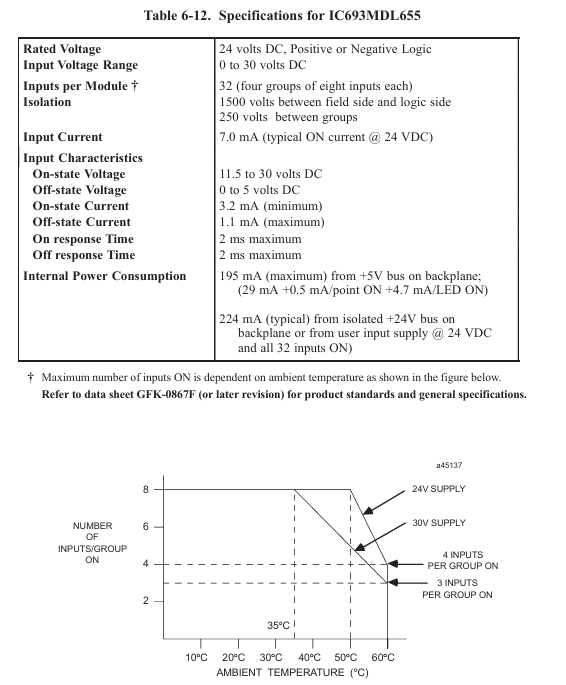
The maximum number of conductive input channels for temperature characteristics varies with the ambient temperature (such as 8 channels per group can be fully conductive at 35 ℃, and only 2 channels per group can be conductive at 60 ℃), and the load configuration needs to be adjusted according to the actual ambient temperature
Installation and wiring information
1. Installation requirements
Installation position: It can only be installed in any I/O slot of the GE Series 90-30 PLC's 5-slot or 10 slot baseboard, without special slot restrictions;
Environmental conditions: Must meet industrial environmental requirements (temperature, humidity, etc. refer to the overall specifications of the PLC system), avoiding high temperature, high humidity, and strong electromagnetic interference scenarios.
2. Wiring configuration
Connector type: The module is equipped with two 24 pin male connectors (Fujitsu FCN-365P024-AU) on the front, with the right connector corresponding to Group A and B inputs, and the left connector corresponding to Group C and D inputs;
Cable selection:
Recommend using GE original pre wired cables, models IC693CBL327 and IC693CBL328 (one end is a matching female head, and the other end is a stripped tin plated wire);
You can also make cables yourself, please refer to Appendix C of the document for the "24 pin connector cable production guide" (IC693CBL327/328 data sheet);
Power supply method: The on-site equipment power supply can be provided by the user themselves, or an isolated 24V DC output power supply can be used on the module I/O connector;
Wiring logic: Each input group needs to be connected to the corresponding common terminal (such as A group connected to ACOM, B group connected to BCOM), and the positive and negative logic is achieved through power polarity switching. For specific wiring, please refer to Figure 6-20 in the document (on-site wiring diagram).
3. Wiring table (core grouping)
The document provides detailed wiring tables for A/B group (right connector) and C/D group (left connector), specifying module points, connector pins, cable pairs, and color coding. The following are examples of key corresponding relationships:
Function Description of Cable Color Matching for Pin Connectors of Grouping Modules
Group A A1 A1 1 Brown Input Signal A1
Group A ACOM A5 3 Orange Group A Common Terminal
B group B1 B1 7 purple input signal B1
Group B BCOM B8 10 Pink/Black Group B Public End
Power supply+24V OUT B6 9 gray/black isolated 24V output
Power supply 0V A7 4 yellow power supply ground
- OMRON
- ABB
- General Electric
- EMERSON
- Honeywell
- HIMA
- ALSTOM
- Rolls-Royce
- MOTOROLA
- Rockwell
- Siemens
- Woodward
- YOKOGAWA
- FOXBORO
- KOLLMORGEN
- MOOG
- KB
- YAMAHA
- BENDER
- TEKTRONIX
- Westinghouse
- AMAT
- AB
- XYCOM
- Yaskawa
- B&R
- Schneider
- KONGSBERG
- NI
- WATLOW
- ProSoft
- SEW
- ADVANCED
- Reliance
- TRICONEX
- METSO
- MAN
- Advantest
- STUDER
- DANAHER MOTION
- Bently
- Galil
- EATON
- MOLEX
- DEIF
- B&W
- ZYGO
- Aerotech
- DANFOSS
- Beijer
- Moxa
- Rexroth
- Johnson
- WAGO
- TOSHIBA
- BMCM
- SMC
- HITACHI
- HIRSCHMANN
- Application field
- XP POWER
- CTI
- TRICON
- STOBER
- Thinklogical
- Horner Automation
- Meggitt
- Fanuc
- Baldor
- SHINKAWA
- Other Brands
- UniOP
- KUKA
- Iba
- Beckhoff
- ADLINK
-
 GE Fanuc VMIVME-5588 High-speed Reflective Memory Board
 -
 VMIC VMIVME-5565 Reflective Memory Board
 -
 VMIC VMIVME-2127 Voltage Source Digital Output Board
 -
 VMIC VMIVME 4512 Analog VME Process PCB Assembly
 -
 GE Fanuc VMIVME-3122-022 Analog I/O Module
 -
 VMIC VMIVME 5576 High Speed Fiberoptic Network Board
 -
 FANUC VMIVME-7452 VMEbus Analog I/O Board
 -
 FANUC VMIVME-2210 VMEbus Digital Output Board
 -
 FANUC VMIVME-7750-734000 VMEbus Single Board Computer
 -
 VMIC VMIVME 2210 VMEbus DO 28V Digital Output Board
 -
 VMIC VMIVME DR11W VMEbus DMA Interface Module
 -
 VMIC VMIVME-2536-200 5V Optically Coupled Digital I/O Board
 -
 VMIC VME-7754 VMIVMF7754-259000 VMEbus Control Card
 -
 VMIC 2170A VME Interface Board
 -
 GE VMIC PMC-5565PIORC-210000 Reflective Memory PMC Node Card
 -
 VMIC VMIVME-7750-750000 VME Single Board Computer
 -
 VMIC VMIVME-7751 VME Single Board Computer
 -
 VMIC 332-004512 Analog VME Process Board
 -
 VMIC VMIVME2528 VME Interface Board
 -
FANUC VMIVME-2120 VME Bus Interface Board
-
 FANUC VMIVME-2540 VME Bus Interface Board
 -
 FANUC VMIVME-3230 VME Bus Interface Board
 -
 FANUC VMIVME-4514 VME Bus Interface Board
 -
 ETEL DSB2S154-211E-000H Servo Amplifier
 -
 ETEL DSCQT112-111-000 Motion Control Module
 -
 ETEL LMG20-050-3QB-211A Servo Motor – High Torque Linear
 -
 ETEL EU-LCP-0-0-1000-01 Communication Card
 -
 ETEL DSA2P174ZA-033A Servo Amplifier Driver
 -
 ETEL EA-P2M-400-15/40A-0100-00 Servo Driver
 -
 ETEL DSC2P152-111-000 Servo Drive Amplifier
 -
 ETEL LMS15-050-3UA-209A Linear Motor
 -
ETEL DSC2P152-111D-000A Controller
-
 ETEL DSB2P131-111E-000B Digital Servo Amplifier Position Controller
 -
 ETEL DSO-PWR111C-000B Power Supply Module
 -
 ETEL DSCDP324-321F-000C Servo Driver
 -
 ETEL DSC2P152-111B-000D Controller
 -
 ETEL DSB2P142-111E-000H Circuit Board
 -
 ETEL LMG05-030-3QA-H01 Linear Motor
 -
 ETEL DSC2P152-111F-000A Controller
 -
 ETEL DSA2S211ZA Servo Drive
 -
 ETEL DSCDM332-112-000 Drive Module
 -
 ETEL DSCDP334-421-000 Digital Position Controller Servo Drive
 -
ETEL EA-P2M-400-15/40A-0100-00 AccurET Servo Drive
-
 ETEL TMA0140-050-3UB-202B Torque Motor
 -
 ETEL DSA1DL1D.PCB Servo Drive Board
 -
 ETEL DSA2DL 1A Servo Drive
 -
 ETEL DSMAX111B-000B Servo Drive
 -
ETEL DSO-PWS111C-000B Power Supply Module
-
 ETEL DSC2P142-111B-000D Servo Drive Amplifier
 -
 ETEL DSC2P132-111D-000A Servo Drive Amplifier
 -
ETEL DSC2P152-111B-000D Servo Drive Amplifier
-
ETEL DSB2P131-121E-000H Servo Drive Amplifier
-
 ETEL DSB2P142-111E-000H Servo Drive Amplifier
 -
ETEL DSO-PWR112C-000A Power Supply Module – High Power
-
ETEL DSO-PWR111C-000A Power Supply Module
-
ETEL DSB2P121-121E-000H Servo Drive Amplifier
-
 ETEL DSB2S134-111E-000H Digital Servo Amplifier
 -
 ETEL RTMA0140-070-AQN-21E Motor
 -
ETEL DSCDP132-111-000 Dual Controller Circuit Board – Motion Control
-
 ETEL LMS15-050-3UA-209Aft Linear Motor
 -
 ETEL DSCDP324-322G-000A Position Controller
 -
ETEL DSA2P174ZA-033A Servo Amplifier Driver
-
 ETEL DSA2P174ZA-017A Servo Amplifier Driver
 -
 ETEL LMD10-050-3QA-223A Linear Motor
 -
ETEL EU-LGP-0-0-1000-00 PCI Network Card
-
ETEL DSO-PWS111C-000B Power Supply Module
-
ETEL DSC2V174-111C-001A Servo Controller
-
 ETEL EA-P2M-600-15/40A-0000-01 AccurET Modular Position Controller
 -
 ETEL RTMA0140-070-AQN-21B DD Motor
 -
 ETEL DSC2P144-421-000 Servo Driver
 -
ETEL EA-P2M-400-15-40A-0100-00 Servo Drive
-
ETEL DSCDM341-111C-000B Board
-
 ETEL LMD10-050-3QA-223A Motor
 -
ETEL RTMA0140-070-AQN-21E DD Motor
-
 ETEL DSCDM342-111-000 Servo Variator
 -
ETEL DSC2P152-111E-000A Servo Amplifier
-
ETEL LMS15-050-3UA-209A Motor
-
ETEL RTMA0140-070-AQN-21C DD Motor – High Torque Direct Drive
-
 ETEL DSCDP334-421G-000A Servo Drive
 -
Etel DSB2S154-211E-000H Digital Servo Amplifier
-
 ETEL EA-P2M-400-15/40A-0100-00 AccurET Servo Drive
 -
 ETEL DSA2P-174ZA-017A Digital Servo Amplifier
 -
ETEL EA-P2M-400-15/40A-0100-00 Servo Drive
-
ETEL LMP07-100-3TAS-229 Linear Motor Primary Part
-
ETEL LMA11-120-3ZA-359A Linear Motor
-
 ETEL EA-S0M-400-40/80A-0000-00 Drive Power Supply
 -
Etel DSCDP334-421-000 Driver
-
ETEL DSCDM341-111C-000B DSCDM Drive Board
-
Etel DSA1 Digital Servo Amplifier
-
ETEL DSA2P174ZA-033A Servo Amplifier
-
ETEL DSCDM342-111-000 Servo Verifier
-
 ETEL LMS15-050-3UA-209A Linear Motor
 -
ETEL P2M-048-2.5/5A AccurET Position Controller – Modular
-
ETEL LMD10-050-3QA-223A Linear Motor – Compact Precision
-
 ETEL EA-P2M-400-05/10A-0000-01 Drive – Precision Motion
 -
ETEL LMP07-100-3TAS-229 Linear Motor Primary Part
-
 ETEL EU-LGP-0-0-0000-00 Motion Control Card – Precision Control
 -
 ETEL DSC2P152-111E-000A Servo Amplifier
 -
ETEL EA-P2M-400-15/40A-0100-01 Servo Drive
-
 ETEL EA-SOM-300-40/80A-0000-00 AccurET Power Supply Module
 -
ETEL LMG10-1050-3QA-H01 Linear Motor
-
 ETEL EA-SOM-300-40/80A-0000-00 AccurET Modular Power Supply
 -
ETEL EA-P2M-400-15/40A-0100-00 AccurET Servo Drive
-
 ETEL EA-P2M-400-15/40A-0100-01 Servo Driver
 -
Etel RTMA0140-070-AQN-21B High Speed Motor
-
ETEL DSC2P141-111-000 Linear Servo Amplifier
-
ETEL DSB2S134-211E-000H Digital Servo Amplifier
-
ETEL 3LM-23C Motion Controller
-
Etel DSO-SER211-000 Power Add-On Board
-
ETEL DSCDP334-421-000 Servo Drive
-
 CTI-Cryogenics 8116071G001 Enhanced On-Board 8F Cryopump
 -
ETEL LMD10-050-3QA-223A Linear Motor
-
Etel DSO-SER211-000 Servo Card Power Add-On
-
ETEL LMG05-050-3QA-213A Linear Motor
-
Etel DSO-SER211-000 Power Add-On Board
-
ETEL EU-LGP-0-0-0000-00 Motion Control Card
-
ETEL EA-P2M-400-15/40A-0100-00 AccurET Servo Drive
-
 ETEL DSA2P1540A Digital Servo Amplifier
 -
ETEL DSC2P131-111-000 Drive Board
-
ETEL DSC2P131-111D-000A Servo Drive
-
Etel SA-IL 03-208 Linear Motor Section 208mm
-
 ETEL EA-P2M-300-4/7.5A-0000-01 AccurET Position Controller
 -
ETEL DSO-SER211-000 Power Board
-
ETEL DSC2P131-111F-000A Servo Amplifier
-
ETEL DSA1P6242B Digital Servo Amplifier
-
ETEL DSC2P131-111B-000B Regulator
-
ETEL DSA2P1540A Digital Servo Amplifier
-
ETEL EA-P2M-048-2.5/5A-0100-01 Drive


