
Woodward LS-521 V2 (Option K12) Circuit Breaker Control Unit
Woodward LS-521 V2 (Option K12) Circuit Breaker Control Unit
Product Overview and Safety Notice
1.1 Product Introduction
LS-521 V2 (Option K12) belongs to the Woodward LS-5 series and is an intelligent control device with dual system monitoring, synchronous grid connection, circuit breaker control, and power parameter measurement functions. Its hardware version is V2, supporting 6 current transformer input terminals, suitable for various wiring modes such as three-phase four wire, three-phase three wire, single-phase three wire, and single-phase two wire.
1.2 Important Safety Warning
Overspeed shutdown protection: The prime mover must be equipped with an overspeed, overtemperature, or overpressure shutdown device independent of the control device to prevent equipment damage or personal injury caused by control failure.
Unauthorized modifications are prohibited: Any modifications that exceed mechanical, electrical, or operational limitations are considered "misuse" or "negligence" and may result in the invalidation of warranty and equipment certification.
Static protection: The controller contains static sensitive components, and body static electricity must be released before operation to avoid contact with circuit board conductors.
Battery charging device: Before disconnecting the battery, the charging device must be turned off to prevent damage to the control system.
1.3 Manual Update and Revision
The latest version of this manual can be obtained through the Woodward official website. Revision history shows that the D version released in April 2022 added synchronous grid connection parameters and CAN commands, and corrected the phase angle definition in the wiring diagram and CAN messages.
Installation and wiring
2.1 Mechanical Installation
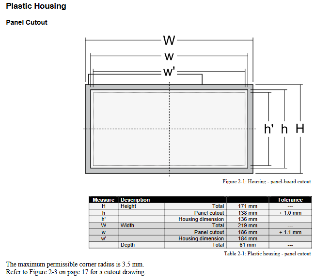
Shell type: Plastic shell with LCD display screen, panel mounted.
Hole size: 138 mm (height) x 186 mm (width), tolerance+1.0/+1.1 mm.
Installation method: Supports fixture fixation or screw fixation, the latter can achieve IP65 protection level.
2.2 Power Supply and Grounding
Power input: 12/24 Vdc, range 8-40 Vdc, recommended to use 6A slow melting fuse or C-type miniature circuit breaker.
Functional grounding: A grounding wire of ≥ 2.5 mm ² must be connected through terminal 55 to prevent the risk of electric shock.
2.3 Voltage and current measurement wiring
2.3.1 Voltage Measurement of System A and System B
Input terminals: divided into two groups of 120 Vac and 480 Vac, cannot be used simultaneously.
Wiring method: Select the corresponding terminal according to the system configuration (such as 3Ph4W, 3Ph3W, 1Ph2W, etc.).
PT setting: The rated voltage of the PT primary and secondary sides needs to be set in the parameters.
2.3.2 Current measurement
CT input: Supports 5A or 1A secondary current, system A supports L1 L2 L3 or single-phase measurement.
Safety precautions: Before disconnecting the CT, the secondary must be short circuited to prevent open circuit high voltage.
2.4 Discrete Input and Relay Output
Discrete Input (DI): 8 channels, supporting positive/negative polarity, configurable as normally open or normally closed.
Relay output: 6 channels, with R5 fixed as "closing CBA", R6 fixed as "opening CBA" in dual relay mode, and the rest can be freely programmed through LogicsManager.
2.5 Communication Interface
Service port: RJ-45 interface, needs to be connected to PC with Woodward DPC cable.
CAN bus: Supports CANopen protocol and requires the installation of 120 Ω terminal resistors at both ends. The maximum length depends on the baud rate (e.g. 125 kbit/s corresponds to 100 meters).
Configuration and parameter settings
3.1 Configuration Method
Front panel operation: Basic settings can be made through buttons and the display screen.
PC software ToolKit: Visualize configuration and data monitoring through Woodward ToolKit software.
3.2 Key parameter group
3.2.1 Language and Clock
Supports multilingual display and can be configured to automatically switch between daylight saving time.
3.2.2 Passwords and Access Levels
CL0 (user level): Monitoring only, no password.
CL1 (Service Level): Password 0001, basic parameters can be modified.
CL2 (temporary debugging level): one-time password, valid for 2 hours.
CL3 (debugging level): Password 0003, full parameter access.
3.2.3 System Management
Device address (1-31), backlight control, key locking, factory reset, etc.
3.2.4 Circuit Breaker Control Configuration
CBA control mode: 1 relay or 2 relay mode.
Synchronization parameters: frequency difference, voltage difference, phase angle compensation, maximum phase angle, etc.
Dead zone closure: Supports dead zone closure between systems, with configurable delay time and voltage threshold.
3.2.5 Monitoring Configuration
System A/B voltage and frequency limits: Set the normal operating window and hysteresis value.
Phase sequence monitoring: can detect system A/B phase sequence errors and phase sequence mismatches.
CAN interface monitoring: Heartbeat timeout alarm can be set.
3.2.6 Measurement Configuration
Rated frequency, voltage, current, power and other reference values.
Voltage measurement method (phase phase or phase neutral point) and phase sequence assumption.
3.2.7 Interface Configuration
CAN baud rate (20 kbit/s to 1 Mbit/s), CANopen master-slave mode, RS-232 parameters, etc.
Operation and Display
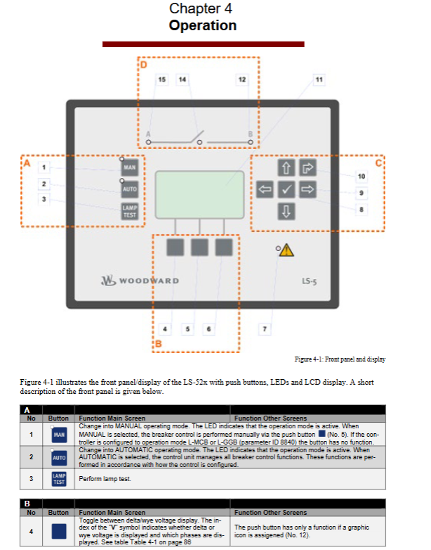
4.1 Front panel layout
Mode button: Switch between manual/automatic mode.
Function buttons: alarm list, main menu, parameter settings, confirm, return, etc.
Indicator lights: System A/B status, circuit breaker status, alarm indication.
4.2 Screen Structure and Navigation
Main screen: displays key parameters such as A/B voltage, frequency, and power of the system.
Alarm List: Display unconfirmed alarms and their occurrence times.
Parameter menu: Access configuration items.
Main menu: Measurement Value, Synchronous Oscilloscope, Counter, Diagnosis, Event History, etc.
4.3 Synchronous oscilloscope function
Graphically display the phase angle difference between system A and B to assist in synchronous operation.
LogicsManager Logic Manager
5.1 Function Overview
LogicsManager allows users to customize control sequences through logical combinations, such as relay actions, alarm responses, etc.
5.2 Logical Elements
Command variables: including alarm class, system status, discrete input/output, etc.
Operators: AND, OR, NAND, NOR, XOR, etc.
Output: Relay or internal function.
5.3 Application Examples
By combining discrete inputs, system states, and alarm conditions, complex chain control logic is achieved.
6、 Communication Protocol and Data Exchange
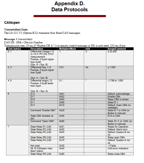
6.1 CANopen Protocol
Sending messages: 4 fixed messages, including voltage difference, frequency difference, phase angle, power, status bit, etc.
Receiving messages: Remote control messages used for circuit breaker operation, alarm confirmation, etc.
6.2 Data Format
Voltage, current, power and other data with scaling factors support the transmission of large-scale measurement values.
Technical data and performance
7.1 Electrical Parameters
Power supply: 8-40 Vdc, power consumption approximately 6W.
Voltage measurement: 120 Vac (maximum 150 Vac) or 480 Vac (maximum 600 Vac).
Current measurement: 1A or 5A CT input, linear range 1.5 x rated value.
Discrete input: 8-40 Vdc, input resistance of approximately 20 k Ω.
Relay output: Contact capacity 2A @ 250 Vac, 2A @ 24 Vdc.
7.2 Environment and Machinery
Working temperature: -20 ° C to+70 ° C.
Protection level: Front panel IP54 (clamp) or IP66 (screw), rear panel IP20.
Vibration and impact: Complies with EN 60255-21 and MIL-STD-810 standards.
Certification: CE, UL/cUL, LR classification society certification.
7.3 Measurement accuracy
Frequency: ± 0.1% (range 85 Hz).
Voltage: ± 1% (range 120/480 V).
Current: ± 1% (range 1/5 A).
Power: ± 2% (range voltage x current).
Appendix and Maintenance Information
8.1 Interference Suppression Circuit
When connecting a 24V relay, it is recommended to use diodes, varistors, or RC circuits to suppress turn off voltage spikes.
8.2 Alarm classification
Class A: Only display, no relay action.
Class B/C: Trigger alarm light and horn.
Class D/E/F: Immediately open the circuit breaker.
8.3 Event History
Record 300 events, including status changes, alarms, and operation records.
8.4 Service Support
Before returning for repair, an authorization number (RAN) must be applied for in advance.
Provide technical assistance, training, on-site debugging and other services
- OMRON
- ABB
- General Electric
- EMERSON
- Honeywell
- HIMA
- ALSTOM
- Rolls-Royce
- MOTOROLA
- Rockwell
- Siemens
- Woodward
- YOKOGAWA
- FOXBORO
- KOLLMORGEN
- MOOG
- KB
- YAMAHA
- BENDER
- TEKTRONIX
- Westinghouse
- AMAT
- AB
- XYCOM
- Yaskawa
- B&R
- Schneider
- KONGSBERG
- NI
- WATLOW
- ProSoft
- SEW
- ADVANCED
- Reliance
- TRICONEX
- METSO
- MAN
- Advantest
- STUDER
- DANAHER MOTION
- Bently
- Galil
- EATON
- MOLEX
- DEIF
- B&W
- ZYGO
- Aerotech
- DANFOSS
- Beijer
- Moxa
- Rexroth
- Johnson
- WAGO
- TOSHIBA
- BMCM
- SMC
- HITACHI
- HIRSCHMANN
- Application field
- XP POWER
- CTI
- TRICON
- STOBER
- Thinklogical
- Horner Automation
- Meggitt
- Fanuc
- Baldor
- SHINKAWA
- Other Brands
- UniOP
- KUKA
- Iba
- Beckhoff
- ADLINK
-
 Basler Electric BE1-700 Digital Protective Relay
 -
 Basler Electric SR8A-2B01B3A Static Voltage Regulator
 -
 Basler Electric SR4A-2B01B3E Static Voltage Regulator
 -
 Basler Electric 9017709102 PC Board
 -
Basler Electric SR4A-2B01B3A Static Voltage Regulator
-
 Basler Electric PRS-250 Veri-Sync Relay
 -
 Basler Electric 9066800102 Excitation Support System
 -
 Basler Electric BE1-87G Generator Differential Relay 9 1708 18 100
 -
 Basler Electric 36T865-2 BE03752001 Power Supply
 -
 Basler Electric M-300 149D940G02 Power Supply
 -
 Basler Electric ACA2040-25GM 4Mp 25Fps Area Scan Camera
 -
 Basler BE1-87G-S1A-A1C-A0N0 Differential Relay
 -
 Basler SR8A-2B06B3E Static Regulator SR8A2B06B3E
 -
 Basler SCP-210 Frequency Controller 9095400100
 -
 Basler BE1-59-A3E-A1J-N1N3F Overvoltage Relay BE159A3EA1JN1N3F
 -
 Basler 9 2011 11 100 Bracket Mounted Terminal Unit
 -
Basler 9 1606 00 101 Voltage Regulator
-
 Basler CBS-377 Current Boost System 9109600102
 -
 Basler 8650C72 Exciter Control Module PCB Rev 5
 -
 Basler C2EE1PA0N1F BE1-32R Reverse Power Relay
 -
 ADLINK HPCI-14S12U - Industrial Control Backplane 12PCI Backplane PCI-14S Passive Backplane
 -
-0010.png) ADLINK PCIe-GIE74C - image acquisition card 4-CH GigE Vision PoE+ Frame Grabber
ADLINK PCIe-GIE74C - image acquisition card 4-CH GigE Vision PoE+ Frame Grabber -
-0010_1.png) ADLINK PCI-8164 - control card 4-Axis Advanced Motion Controller Board
ADLINK PCI-8164 - control card 4-Axis Advanced Motion Controller Board -
 ADLINK PCIe-U304 - 4 Port USB3 PCIe Frame Grabbers USB Screw Hole Card
 -
 ADLINK PCI-9112 - Multi-Function Data Acquisition Card DAQ Card
 -
 ADLINK PCI-7432 - 51-12013-0A50 4-CH Isolated Numérique I/O PCI Cartes Digital I/O Card
 -
 ADLINK PCA-6106P3-0C1 REV.C1 - backplane 6-Slot Passive Backplane Board
 -
 ADLINK PCI-7224 - 24-CH Opto-Isolated Digital I/O PCI Board
 -
 ADLINK CPCI-7433R(G) - Digital Input Board Rear I/O CompactPCI Card
 -
 ADLINK EBP-13E4 - 51-46703-0A30 Industrial PC Backplane Passive Backplane
 -
 ADLINK PCIE-HDV62 - Image acquisition card High Definition Video Frame Grabber
 -
 ADLINK EBP-13E4 - 51-46703-0A30 Industrial Backplane Board Passive Backplane
 -
 ADLINK 90111-B1 / CPCI-6770 - PCB CPU MODULE CompactPCI Single Board Computer
 -
 ADLINK PCI-7248 - DATA ACQUISITION PCI CARD 48-CH Parallel Digital I/O Board
 -
 ADLINK PCI-7230 - 51-12003-0a50 board PCI7230 32-CH Isolated Digital I/O Card
 -
 ADLINK PCI2A000CB - 51-20000-0B30 Multi-Function DAQ Card Baseboard
 -
 ADLINK PCI-8134-005 - 4-Axis Motion Controller Card
 -
 ADLINK PCI-7224 - 24-CH Opto-Isolated Digital I/O PCI Card
 -
 ADLINK PCI-7434 - 64-CH Isolated Digital Output Card
 -
 ADLINK PCI-8132 - motion control card 2-Axis Servo & Stepper Controller
 -
 ADLINK PCI-8134 - Motion Controller PCI Card 4-Axis Controller Board
 -
 ADLINK PCI-8164 - Motion Control Card 51-12406-0A40 4-Axis Controller
 -
 ADLINK 51-12001-0C20 - Circuit Board Data Acquisition Interface Module Hardware
 -
 ADLINK NuPR0-840 - industrial control motherboard Full-Size PICMG CPU Board
 -
 ADLINK PCI-7444 - 51-12023-0A10 card 128-CH Isolated Digital Output Board
 -
 ADLINK PCI-1612B - data acquisition card 4-Port RS-232/422/485 Serial Communication Card
 -
 ADLINK PCI-6208V 009 - 8/16-CH 16-Bit Analog Output Cards PCB-I-E-482=6BX3
 -
 ADLINK NUPRO-935A/LV - industrial control motherboard Full-Size PICMG SBC Board
 -
 ADLINK PCI-9114DG - Multi-Function DAQ Card Data Acquisition PCI Card
 -
 ADLINK ACL-7130 - Data acquisition card Isolated Digital I/O Board
 -
 ADLINK ABX-6300D-4E1-BP - board ABX6300D4E1BP Video Interface Expansion Card
 -
 ADLINK CPCI-6940 - CPCI-6940/D1539/M16-0(EA)-000E 6U CompactPCI Processor Board
 -
 ADLINK NuPRO-760 - industrial control motherboard Half-Size PICMG SBC CPU Board
 -
 ADLINK IMB-M42H (G)-0020 - industrial control motherboard LGA1155 Micro-ATX Mainboard
 -
 ADLINK RTV-24 / PCI-MP4S - 51-12519-1C30 4-Channel Real Time Video Capture Board
 -
 ADLINK PCI-8134 - 4-Axis Servo & Stepper Motion Controller Card
 -
 ADLINK MXC-6101D - V.PC000.002.ST.00 Box PC Configurable Embedded Computer
 -
.png) ADLINK PCI-8134A - 51-12421-0A10 Motion Control Card 4-Axis Controller Card
ADLINK PCI-8134A - 51-12421-0A10 Motion Control Card 4-Axis Controller Card -
 ADLINK DIN-100S / DIN-100SA1 - Technology SCSI-II TB 100-PIN Terminal Block Board
 -
.png) ADLINK DIN-812M001 / DIN812M001 - 51-14034-0A1 51140340A1 Terminal Module Breakout Interface
ADLINK DIN-812M001 / DIN812M001 - 51-14034-0A1 51140340A1 Terminal Module Breakout Interface -
_1.png) ADLINK PCI-8164 - Servo motion control 4-Axis Advanced Controller Card
ADLINK PCI-8164 - Servo motion control 4-Axis Advanced Controller Card -
 ADLINK PCIe-GIE64 - Acquisition card GigE Vision PoE+ Frame Grabber
 -
 ADLINK M-302 - Industrial control motherboard ATX PC Board Mainboard
 -
 ADLINK PCI-8134 - Motion Controller PCI Card 4-Axis Controller Board
 -
 ADLINK PCI-RTV24 - Image capture card Analog Video Frame Grabber
 -
 ADLINK PCI-8102 - Motion control card 2-Axis Servo & Stepper Controller Board
 -
 ADLINK PCI-9112 REV.B1 - Card Multi-Function Data Acquisition Card
 -
 ADLINK HSI-DI32-M-N / HSL-TB32-M-DIN - Discrete I/O MODULE Distributed Automation Module System
 -
 ADLINK PCI-7296 - IO card REV.A3 96-CH Parallel Digital I/O Card
 -
-0020.png) ADLINK DIN-814P-A4 / 814Y - terminal board Motion Control Interface Block
ADLINK DIN-814P-A4 / 814Y - terminal board Motion Control Interface Block -
 ADLINK DIN-814P-A4 - 51-14056-0A10 PCB-I-E-2736=ZA01 Screw Terminal Board Breakout
 -
 ADLINK M-322 - motherboard Industrial Control Computer Mainboard
 -
 ADLINK NUPRO-406 REV:B1 - industrial control motherboard Full-Size PICMG CPU Board
 -
 ADLINK AMP-204C - card DSP-Based 4-Axis Advanced Pulse-Train Controller
 -
 ADLINK HPCI14S REV.B1 - industrial computer baseboard 14-Slot Passive Backplane
 -
 ADLINK PCI-7250 - 8-CH Relay Output & 8-CH Isolated DI PCI Card
 -
 ADLINK EBP-13E2 - baseplate Passive Backplane Industrial Computer Chassis Board
 -
 ADLINK LPCI-3488A - PCI-GPIB card 51-12801-0A30 acquisition card IEEE-488 Interface Board
 -
 ADLINK PCI-6216V-GL - 51-12201-0C30 16-CH 16-Bit Voltage Analog Output Card
 -
 ADLINK ACL-8454 - 16-CH Isolated Digital I/O & 4-CH Counter Card
 -
 ADLINK HPCI-9S7U - backplane Passive Backplane Compatible with NuPRO-A301 852 841 842
 -
 ADLINK DAQ-2010-007 - Simultaneous-Sampling Multi-Function Data Acquisition Card
 -
 ADLINK MP-C154 - 51-64205-0A10 Motion Control Card 4-Axis Controller Board
 -
 ADLINK MXE-202/mSSD16B/WiFi-BT - Matrix Rugged I/O Platform Embedded Fanless Computer
 -
 ADLINK CM-920-R-17 - PC/104-Plus Single Board Computer Module Intel Celeron M
 -
 ADLINK PCI-7250 NSMP - 8-CH Relay Output & 8-CH Isolated DI Card
 -
 ADLINK PCI-8164 - 4-Axis Motion Controller PCI Card W/ Cable and Breakout Box
 -
 ADLINK EMX-100 - Ethernet-based 4-axis Motion Controllers Distributed Motion Module
 -
.png) ADLINK PCI-8134A - Press control card 4-Axis Motion Controller Board
ADLINK PCI-8134A - Press control card 4-Axis Motion Controller Board -
 ADLINK M-845EG REV:3.2 - industrial motherboard Pentium 4 Socket 478 Micro-ATX
 -
 ADLINK PCI-9114A Rev A2 DG - card High-Resolution Multi-Function Data Acquisition Board
 -
 ADLINK IEC-915GV - REV 1.1 Industrial motherboard Socket 478 CPU Board
 -
 ADLINK PCI-9111DG(G) - Data Acquisition Card Multi-Function DAQ Card
 -
 ADLINK HPCI-15S10 REV:B2 - Industrial computer base plate Passive Backplane Board
 -
 ADLINK NuPR0-840 / NuPR0-840DV - industrial control motherboard Full-size PICMG CPU Board
 -
 ADLINK RTV-24 / PCI-MP4S - 51-12519-1C30 4-Channel Real Time Video Capture Board
 -
 ADLINK NUPRO-780 - industrial control motherboard Pentium III Single Board Computer
 -
 ADLINK PCI-7296 - 0050 card 96-CH Opto-Isolated Parallel DIO Card Set
 -
-0040.png) ADLINK NUPRO-780 - industrial control motherboard PICMG Full-Size SBC
ADLINK NUPRO-780 - industrial control motherboard PICMG Full-Size SBC -
 ADLINK PCI-7248 - 51-12006-0A3 002 Pci 7248 48-CH Parallel Digital I/O Card
 -
 ADLINK PCI-7230 - 32-CH Isolated Digital I/O Card
 -
 ADLINK AMP-204C - motion control card 4-Axis Advanced Controller Board
 -
.png) ADLINK PCI-1714UL - Card Ultra High-Speed 4-CH Simultaneous Sampling DAQ
ADLINK PCI-1714UL - Card Ultra High-Speed 4-CH Simultaneous Sampling DAQ -
 ADLINK NuPRO-E330 - industrial computer equipment motherboard PICMG 1.3 SHB SBC
 -
 ADLINK AMP-204C - DSP-Based 4-Axis Advanced Pulse-Train Motion Controller Module
 -
 ADLINK PCI-7256 - 001 51-12206-0A2 REV.A2 LPCI-7256 16-CH Latching Relay Output Card
 -
 ADLINK ND6050 - NUDAM DIGITAL I/0 MODULE Distributed I/O Unit
 -
 ASEM BM100 - Box PC Embedded Fanless Industrial Computer
 -
-3650.png) ADLINK PCI-7250 - PCI Acquisition Card 8-CH Relay Output & Isolated DI Board
ADLINK PCI-7250 - PCI Acquisition Card 8-CH Relay Output & Isolated DI Board -
 ADLINK PCI-8164 - Servo motion control 4-Axis Controller Card
 -
 Basler XR2002F Voltage Regulator 9139400101
 -
Basler 2D80367G23 DXCB De-Excitation Module 1200V 5000A
-
Basler SR4A-2B15B3A Static Regulator 120V 50/60Hz
-
 Basler SSR 125-12NF Static Regulator 9 1859 00 106
 -
 Basler BE1-BPR Breaker Protection Relay 9272000315
 -
 Basler SSR 63-12 Static Regulator 9 1859 00 101
 -
 Basler AEM-2020 Analog Expansion Module
 -
 Basler BE 25231-001 Transformer BE25231001
 -
Basler MVC 108 Manual Voltage Control 9037000102
-
 Basler PSS-100-Y5 Power System Stabilizer 0.1-5.0Hz
 -
Basler Electric BE1A-25-M1G-A6T-N4V1F Sync-Check Relay
-
 Basler Electric SR8A2B10B1A Static Voltage Regulator
 -
Basler Electric SR8A2B10B1A Static Voltage Regulator
-
Basler Electric SSR 125-12 Static Voltage Regulator 9185900102
-
 Basler Electric 90-73900-102 Power Supply (Westinghouse 2374A07G03)
 -
 Basler Electric 9400200117 Control Power Unit 12/24VDC 20W
 -
Basler Electric BE1-87G Solid State Generator Differential Relay
-
 Basler Electric BE1-32R Style C3ED1TA0S1F Solid State Protective Relay


