STOBER POSIDRIVE ® How to install MDS 5000?
Brake chopper opening level 780V/800V
Brake chopper disabled voltage 740V/760V
3. Specification 2/BG2
Parameter Value
Connection voltage 3 × 400V (L1-L3),+32%/-50%, 50Hz; 3×480V(L1-L3),+10%/-58%,60Hz
Power fuse 3 × 50AT
Servo motor operation (servo control mode) - rated current (IN) 3 × 20A
Servo motor operation (servo control mode) - maximum overload of 250%/2 seconds, 200%/5 seconds
Servo motor operation (servo control mode) - clock pulse frequency 8kHz
Three phase current motor operation (V/f, VC, SLVC control mode) - clock pulse frequency 4kHz (adjustable to 16kHz during derating)
Braking resistor (accessory) 22 Ω: maximum 29kW
Power consumption (IN) 280W
Power consumption (Ia=0A) up to 30W (depending on the connected option board and sensor, such as encoder)
The maximum cross-sectional area of the wire is 6mm ²
Weight (unpackaged) 6.1kg
Maximum voltage limit 830V
Brake chopper opening level 780V/800V
Brake chopper disabled voltage 740V/760V
4. Specification 3/BG3
Equipment model MDS 5220 (ID: 44564) MDS 5370 (ID: 44566) MDS 5450 (ID: 44567)
Recommended motor power: 22kW, 37kW, 45kW
Connection voltage 3 × 400V (L1-L3),+32%/-50%, 50Hz; 3 × 480V (L1-L3),+10%/-58%, 60Hz same left same left
Power fuse 3 × 50AgG ² 3 × 80AgG ²-
Servo motor operation (servo control mode) - rated current (IN) 3 × 30A 3 × 50A 3 × 60A
Servo motor operation (servo control mode) - maximum overload of 250%/2 seconds, 200%/5 seconds ³ (average effective current within 10 minutes must not exceed rated current) Same left and same left
Servo Motor Operation (Servo Control Mode) - Clock Pulse Frequency 8kHz Same Left Same Left
Three phase current motor operation (V/f, VC, in preparation: SLVC control mode) - rated current (IN) 3 × 44A 3 × 70A 3 × 85A
Three phase current motor operation (V/f, VC, in preparation: SLVC control mode) - maximum overload of 180%/5 seconds, 150%/30 seconds ³ (average effective current within 10 minutes must not exceed rated current) same as left and right
Three phase current motor operation (V/f, VC, in preparation: SLVC control mode) - clock pulse frequency 4kHz (adjustable to 16kHz during derating) same left and same left
Internal braking resistor 30 Ω: 100W/maximum 21kW Same Left Same Left
External braking resistor (accessories, see Chapter 7.2) 15 Ω: maximum 42kW, same left, same left
Allowable shielded motor cable length of 100m, same left and same left
When Ia=IN, the power consumption is about 350W, about 600W, and about 1000W
When Ia=0A, the maximum power consumption is 55W ⁴ (depending on the connected option board and sensor, such as encoder). Same as left
When there is no core end sleeve in the cross-section of the wire, the maximum area is 35mm ², same left and same left
Dimensions (H × B × T) [mm] 382.5 × 190 × 276 Same Left Same Left
Weight [kg] (unpackaged/packaged) 11.8/13.6 13.2/15.0 13.2/15.0
The maximum voltage limit is 830V, same left and same left
The opening level of the brake chopper is 780V/800V, which is the same as the left
Brake chopper disable voltage 740V/760V same left same left
(4) Mechanical parameters
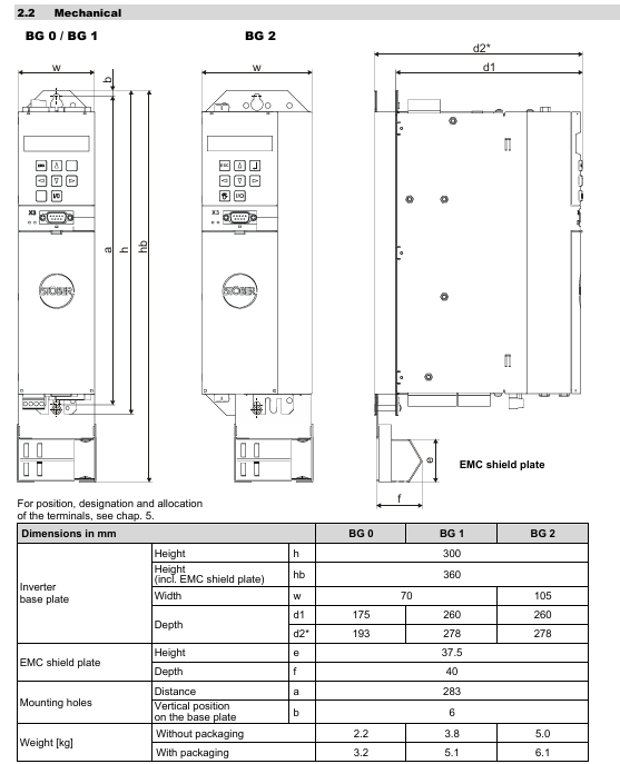
1. BG0/BG1/BG2
Parameter Value
Minimum free space without EMC shielding board [mm] (up/down/right/left) 100/100/5/5
Minimum free space with EMC shielding board [mm] (up/down/right/left) 100/120/5/5
Screw specification M5
2. BG3
Parameter Value
Height [mm] 382.5
Inverter substrate width [mm] 190
Inverter substrate depth [mm] 276
Vertical distance [mm] 365
Number of vertical mounting holes on the substrate: 6
Horizontal distance [mm] 150
Minimum free space [mm] (up/down/right/left) 100/100/5/5
Screw specification M5
Installation points
(1) Mechanical installation
Position requirement: Install vertically inside the enclosed switchgear, leaving a minimum free space (100mm up/down, 5mm left/right; 120mm below with EMC shielding board).
Accessory installation: Before installing the optional modules (fieldbus, I/O terminals), power off and discharge are required, and touching the gold-plated contacts is prohibited; The depth of the bottom braking resistor (RB 5000) is increased by about 20mm, and the EMC shielding board can be replaced with a 24V braking module.
(2) Electrical installation
EMC measures: Separate power lines from signal lines, use shielded wires for motor cables with a large area of shielding layer, and shield brake resistor cables exceeding 30cm.
Power and protection: Use RK1 level fuses (such as Bussmann KTS-R series), and choose 300/500mA or delayed RCD circuit breakers.
DC link coupling: Only three-phase equipment can be coupled, and parameter A38 (set 1 for group 2/3) needs to be set. In case of a fault, the entire power supply needs to be disconnected, and fuses need to be replaced in pairs.
Safe torque shutdown: achieved through the ASP 5001 option, requiring dual shutdown (enable+option), with at least one functional test per month.
Connection Example
(1) Universal Connection Example
1. Connect the 24V DC brake with BRM 5000
Including power fuse, power cut-off, PE, 24V/0V power supply, BRM 5000 module (X300, X302), MDS 5000 X10 power supply, X11 24V, X1 enable, X2 terminal, X20 motor, X21 braking resistor, X4 encoder and other connection methods, marked with only/L optional equipment, DC brake motor only, brake resistor if necessary, shielding for line length>300mm and other precautions.
- ABB
- General Electric
- EMERSON
- Honeywell
- HIMA
- ALSTOM
- Rolls-Royce
- MOTOROLA
- Rockwell
- Siemens
- Woodward
- YOKOGAWA
- FOXBORO
- KOLLMORGEN
- MOOG
- KB
- YAMAHA
- BENDER
- TEKTRONIX
- Westinghouse
- AMAT
- AB
- XYCOM
- Yaskawa
- B&R
- Schneider
- Kongsberg
- NI
- WATLOW
- ProSoft
- SEW
- ADVANCED
- Reliance
- TRICONEX
- METSO
- MAN
- Advantest
- STUDER
- KONGSBERG
- DANAHER MOTION
- Bently
- Galil
- EATON
- MOLEX
- Triconex
- DEIF
- B&W
- ZYGO
- Aerotech
- DANFOSS
- Beijer
- Moxa
- Rexroth
- Johnson
- WAGO
- TOSHIBA
- BMCM
- SMC
- HITACHI
- HIRSCHMANN
- Application field
- XP POWER
- CTI
- TRICON
- STOBER
- Thinklogical
- Horner Automation
- Meggitt
- Fanuc


