
HIRSCHMANN MICE series modular industrial communication equipment
HIRSCHMANN MICE series modular industrial communication equipment
Product Core Overview
(1) Product positioning and design objectives
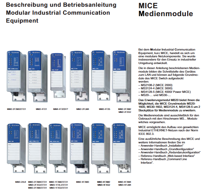
The MICE series is a modular network component designed specifically for industrial environments. Its core function is to build a switched industrial Ethernet that complies with the IEEE 802.3 standard, which can adapt to various complex industrial scenarios such as standard industry, marine, railway (track area), substations, etc. It has industrial grade characteristics such as anti-interference, resistance to harsh environments, and flexible scalability, meeting the stability and reliability requirements of industrial equipment interconnection and data transmission.
(2) Compliance certification and scope of application
Core Certification Standards
European compliance: 2004/108/EG Electromagnetic Compatibility Directive, 2011/65/EU (RoHS) Hazardous Substance Restriction Directive, ATEX 94/9/EG Explosion Protection Directive (applicable to gas explosion hazardous areas);
International standards: FCC Part 15 (US Electromagnetic Compatibility Standard), IEC 60825-1 (Laser Safety Level 1), IEC 60079 series (Explosion proof Standard), IEEE 802.3 (Ethernet Standard), IEEE 802.3af (PoE Power Supply Standard);
Other certifications: CE, UL 508, ISA 12.12.01 (Industrial Control Equipment Safety), etc. Some models support classification society certification (GL, ABS, BV, DNV, etc.).
Applicable scenario segmentation
Standard application: Office areas, commercial premises, small business industrial environments (compliant with EN 61131-2);
Marine application: interconnection of merchant ship equipment (model including B/E/H/S authorization code);
Railway application: Track area communication (compliant with EN 50121-4, with model including E/H/S authorization code);
Substation application: Power system communication (compliant with EN 61850-3, IEEE 1613, with model number including H/S authorization code).
Full analysis of module system
The MICE series adopts a modular architecture of "basic module+expansion module+functional module", and each module can be flexibly combined to adapt to different industrial communication needs.
(1) Basic module (Switch Grundmodule)
As the core carrier of the device, it supports the access of various media modules and expansion modules. The main models and features are as follows:
Series representative models, core features, adaptation and expansion
MICE 2000 MS2108-2 10/100 Mbit/s rate support, basic industrial grade design for all MM2 series media modules and MB20 expansion modules
MICE 3000 MS3124-4 10/100 Mbit/s rate support, some models are compatible with PTP protocol MM3 series media modules, MB20 expansion modules
MICE 4000/Power MICE MS4128-5 supports 10/100/1000 Mbit/s gigabit rates and has power expansion capabilities for MM4 series media modules, SFP modules, and MB20 expansion modules
Other basic modules MS20-..., MS30-... Lightweight design, adapted to specific scene simplification requirements corresponding to series of media modules
(2) Medium module
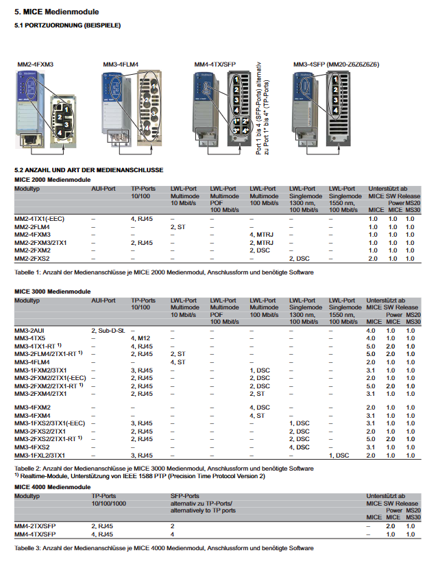
As an interface module between devices and LAN, it provides different types of communication ports (Twisted Pair/TP, Optical Fiber/LWL, AUI, etc.), classified according to the adaptation basic module series as follows:
1. MICE 2000 series media module (10/100 Mbit/s)
Module model, port configuration, interface type, power consumption, typical applications
MM2-4TX1 (- EEC) 4 TP ports RJ45 0.8W short distance industrial equipment interconnection (such as sensors, IP phones)
MM2-2FLM4 2 multi-mode LWL ports (10 Mbit/s) ST - Low rate optical fiber transmission scenario
MM2-4FXM3 4 multi-mode LWL ports (100 Mbit/s) MTRJ 6.8W multi device optical fiber interconnect, requiring high-density ports
MM2-2FXM3/2TX1 2 multi-mode LWL ports+2 TP ports MTRJ+RJ45 3.8W hybrid medium (optical fiber+Ethernet cable) transmission scenario
MM2-2FXM2 2 multi-mode LWL ports (100 Mbit/s) DSC 3.8W optical fiber communication requirements for specific interface types
MM2-2FXS2 2 single-mode LWL ports (100 Mbit/s, 1300nm) DSC 3.8W medium short distance single-mode optical fiber transmission
2. MICE 3000 series media module (10/100 Mbit/s, partially supports PTP)
Module model, port configuration, interface type, power consumption, special characteristics
MM3-2AUI 2 AUI ports Sub-D-St. 3.4W old industrial equipment AUI interface adaptation
MM3-4TX5 4 TP ports M12 0.8W industrial environment foolproof interface, anti vibration
MM3-4TX1-RT 4 TP ports RJ45 0.8W support IEEE 1588 PTPv2, precise clock synchronization
MM3-4FLM4 4 multi-mode LWL ports (10 Mbit/s) ST 5.0W multi port low-speed optical fiber transmission
MM3-2FXM4/2TX1 2 multi-mode LWL ports+2 TP ports ST+RJ45 3.8W mixed medium transmission, compatible with ST interface optical fiber
MM3-4FXS2 4 single-mode LWL ports (100 Mbit/s, 1300nm) DSC 6.8W high-density single-mode optical fiber interconnect
MM3-1FXL2/3TX1 1 single-mode LWL port (100 Mbit/s, 1550nm)+3 TP ports DSC+RJ45 3.4W long-distance single-mode optical fiber+short distance network cable mixed scenario
3. MICE 4000 series media module (1000 Mbit/s, gigabit rate)
Module model, port configuration, interface type, power consumption, core characteristics
MM4-4TX/SFP 4 TP ports+4 SFP slots (mutually exclusive) RJ45+SFP 9.0W Gigabit speed, TP and SFP optical modules can be switched for use
MM4-2TX/SFP 2 TP ports+2 SFP slots (mutually exclusive) RJ45+SFP 5.8W lightweight gigabit hybrid media transmission
4. Open variant series media module (custom port configuration)
Support the selection of port types (TP/LWL/SFP/Colombo, etc.) according to requirements, suitable for personalized scenarios. The core models are as follows:
Module model, port configuration speed, support for special functions, power consumption
MM20-... (such as MM20-Z6Z6Z6Z6) 4 SFP slots (100 Mbit/s) 10/100 Mbit/s replaceable SFP module, flexible adaptation to optical fiber type 8.0W
MM22-T1T1T1T1 4 TP ports (PoE support) 10/100 Mbit/s support IEEE 802.3af PoE power supply 0.8W
MM23-... SAHH (such as MM23-M2M2T1T1) 2 multi-mode LWL ports+2 TP ports 10/100 Mbit/s support PTPv2 clock synchronization 6.0W
MM24-OIOIOIO 4 digital inputs+4 digital outputs - Industrial actuator/sensor switch control 7.5W
MM33-O7O79999... SAHH 2 Combo ports (TP/SFP mutually exclusive) 1000 Mbit/s Gigabit speed, supporting PTPv2 7.5W
(3) Expansion module (Erweiterungsmodul)
The model is MB20 (formerly known as MB-2T), with the core function of expanding 2 media module slots for designated basic modules. The compatible models include MS201600, MS30-1602, MS3124-4, MS4128-5, supporting live installation, with a power consumption of 0W, storage temperature range of -40 ℃~+70 ℃, working temperature range of 0 ℃~+60 ℃, order number 943 733-102.
(4) Functional modules
1. SFP optical module (Optische transceiver)
It is divided into two categories: Fast Ethernet (100 Mbit/s) and Gigabit Ethernet (1000 Mbit/s), supporting multimode (MM), single-mode (SM), and long-distance (LH) optical fiber transmission. The core parameters are as follows:
Type represents model, wavelength, optical fiber type, maximum transmission distance, system attenuation
Fast Ethernet SFP M-FAST-SFP-MM/LC 850nm 50/125µm MM 5km 0-11dB
M-FAST-SFP-SM+/LC 1310nm 9/125µm SM 29km 10-29dB
M-FAST-SFP-LH/LC 1550nm 9/125µm SM 86km 24-86dB
Gigabit Ethernet SFP M-SFP-SX/LC 850nm 50/125µm MM 550m 0-7.5dB
M-SFP-LX/LC 1310nm 9/125µm SM 20km 0-11dB
M-SFP-LH+/LC 1550nm 9/125µm SM 120km 15-32dB
M-SFP-BIDI series 1310/1550nm 9/125 µ m SM 42km 5-20dB
2. PoE Media Module (MM22-T1T1T1T1)
Supports IEEE 802.3af standard PoE power supply, providing 4 10BASE-T/100BASE-TX RJ45 ports, which can supply power to IP phones, cameras, sensors and other terminals through Ethernet cables (maximum support for Class 0/3 devices). The power supply method is "idle line pair (Pins 4&5, 7&8)" and needs to be matched with HIRSCHMANN RPS 60/48V EEC power supply (or external power supply that complies with NEC Class 2 standard). The power requirements include: isolation strength of 2250V DC (1 minute), output power<100W, current<2A, and compliance with IEC 60950-1 "Limited Power Source" standard.
3. Digital I/O module (MM24)
Provide 4 digital input ports and 4 digital output ports, which can connect various actuators (such as relays, solenoid valves) and sensors (such as proximity switches) in industrial scenarios, to achieve the acquisition and control of switch signals. The working temperature is 0 ℃~+60 ℃, the storage temperature is -40 ℃~+70 ℃, and the power consumption is 7.5W.
Installation, disassembly, and debugging process
(1) General Installation Principles
Supports hot swapping: Media modules, MB20 expansion modules, and SFP modules can all be installed/removed during device operation without the need for power outage;
Personnel qualifications: Electrical wiring, module replacement, and other operations must be carried out by professionally trained personnel to avoid electric shock or equipment damage;
Tool restrictions: It is prohibited to insert sharp objects (such as thin screwdrivers, wires, needles, etc.) into the interior of the equipment to prevent circuit short circuits or component damage;
Inspection requirements: Before installation, it is necessary to confirm that the module is not damaged during transportation, the interface is not loose or oxidized, and the screws and other fasteners are complete.
(2) Specific module installation steps
1. Installation of media module
Remove the plastic cover corresponding to the interface of the MICE basic module;
Align the media module with the slot and insert it smoothly, ensuring that the interface between the module and the base module is fully aligned;
Fix the four corners of the module with 4 screws, tightening with moderate force (to avoid damaging the module housing);
Check whether the DIP switch settings on the module (such as SQE Test, DTE Power Monitor) meet the usage requirements (default state is OFF);
Connect the signal line (Ethernet cable/optical fiber) and ensure that the interface buckle is locked in place.
2. SFP module installation
Remove the protective cover of the SFP slot and confirm that the slot is free of dust and foreign objects;
Turn off the locking device of the SFP module and insert the module smoothly into the slot until you hear a "click" locking sound from the buckle;
Connect the optical fiber jumper and pay attention to the cleanliness of the optical fiber interface (to avoid dust affecting transmission);
Caution: Only use HIRSCHMANN original SFP modules, non original modules may cause compatibility issues or equipment failures.
3. Installation of MB20 expansion module
Loosen the upper and lower fixing screws on the right side of the MICE basic module (rotate 1-3 turns without completely disassembling);
Remove the side cover of the basic module;
Fix the basic module on the guide rail (if not installed);
Push the MB20 expansion module along the guide rail to fit snugly with the base module, ensuring complete interface docking between modules;
Re tighten the two fixing screws on the basic module to secure the MB20 module.
4. Debugging and Startup
Power supply connection: Connect the NEC Class 2 standard power supply voltage through the terminal block of the basic module, lock the terminal block to prevent loosening;
Status check: Observe the LED indicator light on the module - the green Power light on indicates normal power supply; The port LED (green/yellow) status reflects the connection and data transmission status of the port (specific meaning depends on device settings);
Functional testing: Verify device interconnectivity through Ping commands and industrial communication protocol testing (such as Modbus, Profinet). The PoE module needs to test whether the terminal power supply is normal.
(3) Dismantling process
Disconnect the signal line of the module (the optical fiber needs to be pulled out first to avoid breakage);
Loosen the module fixing screws (media module) or unlock the SFP module locking device (SFP module);
Smoothly unplug the module to avoid violent pulling (to prevent damage to the interface pins);
Install protective covers for idle slots to prevent dust from entering.
Safety regulations and precautions
(1) Electrical safety
Power supply limitation: All modules only support NEC Class 2 standard power supply voltage. PoE modules require 48V DC safe low voltage and are prohibited from accessing voltage beyond specifications;
Explosion proof requirements: When used in Class I, Division 2, Groups A/B/C/D explosive hazardous areas, it is necessary to ensure that the equipment has been labeled with the corresponding explosion-proof identification, and only plug and unplug modules in environments where the system is powered off or there is no concentration of flammable gases; Replacing modules may affect explosion-proof compatibility and require the use of original spare parts;
Grounding requirements: The shielding layer of Twisted Air cables should be electrically conductive with the front panel of the equipment, and avoid forming a grounding loop during wiring to prevent electromagnetic interference.
(2) Static Electricity Protection (ESD)
The module contains electrostatic sensitive components (such as chips and interface circuits), and operation must comply with the IEC/TR 61340-5-2 standard:
Operators need to wear anti-static wristbands or touch grounded metal objects to release static electricity;
When storing modules, they should be placed in anti-static packaging bags to avoid contact with materials that are prone to static electricity, such as synthetic fibers and plastics;
It is prohibited to touch the exposed metal parts of the module's pins, interface gold fingers, etc. with your hands.
(3) Electromagnetic Compatibility (EMC)
The equipment has a Class A electromagnetic radiation rating and may cause radio interference when used in residential areas. Users are responsible for eliminating the interference themselves;
Strictly follow the wiring specifications in the manual during installation, use shielded cables (such as STP network cables), and avoid parallel laying with power cables (minimum spacing ≥ 30cm);
The equipment must meet the following EMC anti-interference standards:
Electrostatic discharge (EN 61000-4-2): Contact discharge ± 6kV, air discharge ± 8kV;
Electromagnetic radiation (EN 61000-4-3): 80~3000MHz, 10V/m;
Surge (EN 61000-4-5): Power port ± 4kV, data port ± 2kV;
Fast transient pulse (EN 61000-4-4): power port ± 2kV, data port ± 4kV.
(4) Environmental safety
Temperature limit: Standard module working temperature is 0 ℃~+60 ℃, expansion type (T/E grade) working temperature is -40 ℃~+70 ℃, storage temperature is -40 ℃~+85 ℃ (E grade with Confocal Coating anti condensation coating);
Humidity and air pressure: working humidity of 10%~95% (no condensation), maximum altitude of 2000m (795hPa), if exceeding the altitude, please consult the manufacturer in advance;
Pollution level: The environmental pollution level for use must be ≤ 2 (in accordance with IEC 60664-1), and should be avoided in environments with dust, oil, and corrosive gases. Otherwise, an enclosure with a protection level of IP54 or higher must be equipped.
(5) Other safety requirements
Cable specifications: Only use copper core wires with a temperature rating of 60/75 ℃ or 75 ℃. Twisted Pair cables require 4 pairs of types (such as Cat5e, Cat6), and PoE module cable length ≤ 3m;
Lid opening restriction: The device casing can only be opened by authorized HIRSCHMANN technicians. Unauthorized lid opening may result in equipment damage or loss of warranty eligibility;
Recycling requirements: After the product is scrapped, it must be classified and recycled according to local electronic waste regulations, and it is prohibited to dispose of it at will (including harmful substances, which need to be professionally handled).
Summary of Core Technical Parameters
(1) Physical and mechanical parameters
Module series dimensions (width x height x depth) Protection level Vibration resistance (IEC 60068-2-6) Impact resistance (IEC 60068-2-27)
MM2 series 38mm × 110mm × 79mm IP20 2Hz~13.2Hz (1mm amplitude); 8.4Hz~150Hz(1g) 15g,11ms
MM3/MM4 series 38mm × 110mm × 119mm IP20 5Hz~8.4Hz (3.5mm amplitude); 8.4Hz~150Hz(1g) 15g,11ms
MB20 expansion module compatible with basic module size IP20, same as basic module
Open variant series 38mm × 110mm × 79/119mm IP20 adapted to application scenarios 15g, 11ms
(2) Environmental parameters
Parameter standard type (S-level) extended type (T/E level)
Working temperature: 0 ℃~+60 ℃ -40 ℃~+70 ℃
Storage temperature -40 ℃~+70 ℃ -40 ℃~+85 ℃
Relative humidity 10%~95% (no condensation) 10%~95% (no condensation)
Maximum altitude 2000m (795hPa) 2000m (795hPa, customizable for higher altitudes)
Pollution Level 2 (IEC 60664-1) 2 (IEC 60664-1)
(3) Transmission performance parameters
1. Wired Port (TP)
Speed cable type maximum transmission distance interface standard
10BASE-T Cat3 and above 100m IEEE 802.3
100BASE-TX Cat5 and above 100m IEEE 802.3u
1000BASE-T Cat5e and above 100m IEEE 802.3ab
Features support Autocrossing, Autonegotiation, and Autopolarity
2. Optical fiber port (LWL)
Rate, optical fiber type, wavelength, maximum transmission distance, system attenuation
10BASE-FL (multimode) 62.5/125 µ m MM 850nm 2km 0-12.5dB
100BASE-FX (multimode) 50/125 µ m MM 850nm 5km 0-8dB
100BASE-FX (Single Mode) 9/125 µ m SM 1300nm 30km 0-16dB
1000BASE-SX (multimode) 50/125 µ m MM 850nm 550m 0-7.5dB
1000BASE-LX (Single Mode) 9/125 µ m SM 1310nm 20km 0-11dB
1000BASE-LH (Single Mode) 9/125 µ m SM 1550nm 120km 15-32dB
(4) Power consumption
Unit conversion of module type power consumption range (Btu/h)
TP media module (such as MM2-4TX1) 0.8W 2.8
Multimode LWL dielectric module (such as MM2-4FXM3) 6.8W 23.2
Gigabit media module (such as MM4-4TX/SFP) 9.0W 30.8
PoE module (MM22-T1T1T1T1) 0.8W (excluding terminal power supply) 2.8
Digital I/O module (MM24) 7.5W-
SFP module 0W (dependent on basic module power supply) 0
MB20 expansion module 0W 0
Product code and ordering information
(1) Open variant series product coding rules
The product code consists of "product prefix+port configuration+temperature level+authorization code", and the meanings of each field are as follows:
Product prefix (1-4 digits): MM20 (10/100M standard) MM21(10/100M PTPv2)、MM22(10/100M PoE)、MM23(10/100M PTPv2)、MM24( Digital I/O, MM30 (1000M standard) MM33(1000M PTPv2);
Port configuration (bits 5-13): The 5th bit is the delimiter "-", bits 6-7 are the type of port 1 (such as T1=RJ45, M2=multimode DSC, O7=Combo SFP), bits 8-9 are the type of port 2, bits 10-11 are the type of port 3, and bits 12-13 are the type of port 4 (99=empty port);
Temperature rating (14 digits): S (standard: 0 ℃~+60 ℃), T (extension: -40 ℃~+70 ℃), E (extension+anti condensation coating: -40 ℃~+70 ℃);
Authorization code (15 digits): A (CE+UL 508+ISA 12.12.01), B (including ATEX+classification society), E (including railway certification), H/S (including substation certification), Y (CE+UL 508), Z (CE only).
Example: The module corresponding to the code MM30-07070707SA is a "1000M standard media module, 4 Combo SFP ports, standard temperature rating, CE+UL 508+ISA 12.12.01 certification", equivalent to MM4-4TX/SFP (order number 943010-001).
(2) Core module order number
Module type represents model and order number
Basic module MS2108-2- (ordered separately, needs to be paired with media module)
Media module MM2-4TX1 943 722-101
MM3-2AUI 943 840-101
MM4-4TX/SFP 943 010-001
Expansion module MB20 943 733-102
SFP module M-SFP-LX/LC 943 015-001
PoE power supply RPS60/48V EEC 943 952-001

- OMRON
- ABB
- General Electric
- EMERSON
- Honeywell
- HIMA
- ALSTOM
- Rolls-Royce
- MOTOROLA
- Rockwell
- Siemens
- Woodward
- YOKOGAWA
- FOXBORO
- KOLLMORGEN
- MOOG
- KB
- YAMAHA
- BENDER
- TEKTRONIX
- Westinghouse
- AMAT
- AB
- XYCOM
- Yaskawa
- B&R
- Schneider
- KONGSBERG
- NI
- WATLOW
- ProSoft
- SEW
- ADVANCED
- Reliance
- TRICONEX
- METSO
- MAN
- Advantest
- STUDER
- DANAHER MOTION
- Bently
- Galil
- EATON
- MOLEX
- DEIF
- B&W
- ZYGO
- Aerotech
- DANFOSS
- Beijer
- Moxa
- Rexroth
- Johnson
- WAGO
- TOSHIBA
- BMCM
- SMC
- HITACHI
- HIRSCHMANN
- Application field
- XP POWER
- CTI
- TRICON
- STOBER
- Thinklogical
- Horner Automation
- Meggitt
- Fanuc
- Baldor
- SHINKAWA
- Other Brands
- UniOP
- KUKA
- Iba
- Beckhoff
-
 Basler DECS-200-2L Digital Excitation Control
 -
 Basler BE1-47N Voltage Phase Sequence Relay
 -
 Basler AEC63-7 Analog Excitation Controller 220-277V
 -
 Basler BE1-50/51B-107 Overcurrent Relay
 -
 Basler Electric BE1‑32R BE1‑E1P‑BON0F Protective Relay
 -
 Basler BE1-25 Solid State Time Overcurrent Relay M1EA6PA5S1F
 -
 Basler MVC 232 Manual Voltage Control Module 90 37000 103 60VAC 55VDC
 -
 Basler RAL6144-16GM Racer GigE Line Scan Camera
 -
 Basler SSR 63-12 Static Voltage Regulator
 -
 Basler BE1-51A Overcurrent Relay
 -
 Basler BE1-87T Solid State Protective Relay
 -
 Basler SR4A2B01B3A Static Voltage Regulator
 -
 Basler SSR 32-12 Static Voltage Regulator
 -
 Basler TRR00696 Transformer 1KVA 115V
 -
 Basler DECS-100-B15 AVR Replacement
 -
Basler BE1-27 Under-Voltage Relay
-
 Basler ACA2000-50GM Interface Module
 -
 Basler AEC63-7 Analog Excitation Controller
 -
 Basler PRS 250 Veri-Sync Relay
 -
 Basler SR4A-2B15B3A Static Voltage Regulator
 -
Basler BE1-32R Power Relay
-
Basler SR8A-2B06B3E Static Voltage Regulator
-
Basler BE1-81 O/U Frequency Relay
-
 Basler BE1-51A-K2E-W6M-B1N0F Overcurrent Relay
 -
Basler BE1-851 Overcurrent Relay G3A1S1 – 48-125V AC/DC
-
 Basler BEI-51 Overcurrent Relay – NSN 5945-01-293-2363
 -
Basler Electric L301KC Protective Relay – L301KC
-
 Basler DECS-100-B15 Automatic Voltage Regulator – Generator AVR
 -
 Basler SR4A-2B15B3A Static Voltage Regulator – SR4A2B15B3A
 -
 Basler UF 312 Under Frequency Protective Module – 9094700100
 -
Basler Electric MVC 232 Manual Control Module – 60VAC 55VDC 20A
-
Basler PRS 250 Veri-Sync Relay – Generator Synchronizing Relay
-
 Basler DECS-100-A05 Digital Regulator Review
 -
 Basler AEM-2020 Analog Expansion Module Specs
 -
 Basler DECS-100-B15 Digital Excitation Specs
 -
Basler Electric 9125600106 Regulator Component
-
Basler BE1-51A-K1E-W6M-B1N0F Overcurrent Relay
-
 Basler MVC-301 MVC 300 Excitation Controller
 -
 Basler SSR 32-12 Static Voltage Regulator
 -
 Basler 9-2849-00-101 Control Module
 -
Basler BE1-51A Overcurrent Relay
-
 Basler BE1-51/27R Overcurrent Relay
 -
 Basler BE1-51 Overcurrent Relay
 -
 Basler SR8A-2B15B3A Static Voltage Regulator
 -
 Basler BE32965001 Transformer and Timer Board
 -
 Basler 9174700100 EL200-7 Excitation Limiter
 -
 Basler BE2000E AVR Voltage Regulator
 -
Basler BE1-87G Differential Relay
-
 Basler BE21834001 Generator Control Module
 -
Basler DECS-100-B15 AVR
-
 Basler D90 96801 100 PCB Card
 -
 Basler XR2002F Voltage Regulator (110 VAC, 48-480 Hz)
 -
 Basler SR8A-2B14B3A Regulator
 -
 Basler 9561500100 Module
 -
 Basler DECS-400 BE1-11 System
 -
 Basler DECS-100-B15 Excitation Control
 -
 Basler SCP 210 Frequency Controller
 -
Basler SR4A-2B15B3A Static Voltage Regulator
-
Basler BE1-32R Power Relay
-
 Basler PIA2400-17GM Power Interface Adapter
 -
 Basler MVC 232 Manual Voltage Control Module
 -
 Basler SSR 32-12 Static Voltage Regulator
 -
Basler 5MW AVR Generator Voltage Regulator
-
 Basler VR63-4B Voltage Regulator
 -
Basler DECS-100-A05 AVR for Engine Generator
-
Basler DECS-100-B15 Automatic Voltage Regulator
-
Basler BE1-32R Directional Power Relay
-
Basler BE1-87B Differential Relay
-
 Basler UFOV 260A Protective Module
 -
 Basler 9-2614-02-100 PCB Rev M
 -
Basler DECS-100-B15 Digital AVR
-
 Basler 9284900103 PS DECS-400N
 -
 Basler D4N3H1U Intertie Protection
 -
 Basler DECS-100-B15 A15 AVR
 -
 Basler KR4F Voltage Regulator
 -
 Basler BE26434 T14 Transformer
 -
 Basler SR8A-2B15B3A Regulator
 -
 Westinghouse 774B472A12 AR Relay
 -
Basler DECS-100-B15 AVR
-
Basler XR2002F Regulator 110V
-
Basler SR125-E Static Regulator
-
Basler SSR 125-12 Regulator
-
Basler MOC2599 Motor Pot
-
 Basler BE1-DFPR Feeder Relay
 -
 Basler CBS 305 Current Boost
 -
Basler BE1-25 AutoSync
-
Basler MVC 300 Voltage Control
-
 Basler BE3-25A AutoSync
 -
 Basler KR7FF Static Regulator
 -
Basler 90-49000-100 Regulator
-
 Basler 880 kVA Dry Type Transformer Specs
 -
Basler Electric BE1-25 Sync-Check Relay Specs
-
 Basler SSR 125-12 Voltage Regulator Specs
 -
 Basler Electric BE1-851 Overcurrent Relay Review
 -
Basler Electric 149D930G02 Control Sub-Assembly
-
 Basler Electric BE1-81O/UT Frequency Relay Specs
 -
 Basler Electric BE1-51/27C Overcurrent Relay
 -
 Basler Electric 149D956G02 Industrial Component
 -
Basler Electric BE1-51A Overcurrent Relay Specs
-
 Basler Electric BE1-40Q Loss of Excitation Relay
 -
Basler DECS-200 Excitation Control System
-
 Basler DECS-200 Voltage Regulator 56-277V AC / 125V DC
 -
Basler BE1-87T Transformer Differential Relay
-
 Basler RDP-110-S1 Protection Relay
 -
 Basler BE1-700V Digital Protective Relay
 -
 Basler BE1-951 Overcurrent Protection System
 -
 Basler DECS-300 Digital Excitation Control
 -
 Basler DECS-200 Digital Excitation Control
 -
 Basler DECS-200-1C Excitation Control System
 -
Basler DECS-200-1L Digital Excitation Control
-
 Basler Electric BE1-GPS Generator Protection System
 -
Basler Electric DECS-200-1C Digital Excitation Controller
-
 Basler Electric DECS125-15 Excitation Control with Power Module
 -
Basler Electric BE1-87G Differential Relay
-
 Basler Electric BE1-11 Protection System I5A3M2P2N0EA00
 -
Basler Electric DECS-200-1C Excitation Control System
-
Basler Electric BE1-11g Generator Protection Relay
-
Basler Electric DECS 125-15-B2C1 V2.0.9 Excitation Control
-
Basler Electric BE1-81O/UT3ED1JA7N2F Frequency Relay
-
Basler Electric BE1-81O/UT3EE1YB7N1F Frequency Relay
-
 Basler Electric DECS-200-1L Digital Excitation Control System
 -
Basler DECS125-15-B2C1 Excitation Control
-
 Basler 9507900205 SSR Retrofit Voltage Regulator
 -
 Basler BE2000E Digital Voltage Regulator
 -
 Basler BE1-GPS Generator Protection System
 -
Basler DECS-250-CN1CN1N Digital Excitation Control
-
 Basler DGC-2020 Genset Controller
 -
Basler BE1-81O UT3ED1LA7N0F Frequency Relay (Variant)


