
ABB MNSiS Motor Control Center MConnect Interface
Target users: Control and application engineers who need to obtain MNS iS data and perform system integration, requiring users to have basic knowledge of fieldbus (such as PROFIBUS, Modbus).
ABB MNSiS Motor Control Center MConnect Interface
Core positioning and scope of application
Associated System: Designed specifically for MNS iS System Release 7.6 to guide communication and control integration of MConnect interfaces, supporting the integration of MNS iS as a fieldbus component into PLC or higher-level process control systems (PCS/DCS).
Target users: Control and application engineers who need to obtain MNS iS data and perform system integration, requiring users to have basic knowledge of fieldbus (such as PROFIBUS, Modbus).
Basic concepts and terminology definitions
The document provides explanations for over 30 core terms and abbreviations, covering technical terms, protocols, components, etc. The key terms are as follows:
Abbreviations/full names of terms/Chinese core explanation
Aspect Object ABBAspect is a computerized representation of real/virtual objects (such as pumps, services) that are described and structured through "attributes"
Standardized products that can be directly purchased and used in the COTS commercial spot product market
DTM Device Type Manager is a software module used to manage devices through fieldbus (such as PROFIBUS), supporting frameworks such as PactWare
GSD file device description file (German) PROFIBUS-DP/DP-V1 slave station hardware description file, used for device configuration
MCC motor control center is a switchgear used for motor control and protection, which is one of the core application scenarios of MNS iS
MODBUS RTU Modbus Remote Terminal Unit Protocol Fieldbus Communication Protocol, the core protocol for MConnect and circuit breaker communication
PNIO PROFINET IO is an open standard based on industrial Ethernet (IEC 61158/61784) used for distributed peripheral devices and automation
The SNTP Simple Network Time Protocol is a protocol that controls network time synchronization through Ethernet
The remaining terms (such as HMI, LVS, OPC, etc.) revolve around low-voltage switchgear, communication protocols, and system components, laying the foundation for subsequent technical content.
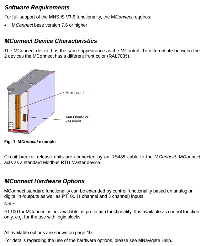
Hardware and software requirements
1. Hardware requirements
(1) MConnect hardware model and configuration
The MConnect hardware is based on the motherboard and is paired with different functional modules (analog input/output, digital input/output, PT100 temperature acquisition) to form 28 models. The core model identification rules are as follows (taking the 1TGE120071R series as an example):
Model ID Core Configuration Function Extension
1TGE120071R1000 motherboard only, no additional IO or temperature acquisition
1TGE120071R1001 motherboard+AIAO (Analog IO) supports analog signal input and output
1TGE120071R1100 motherboard+4DI2DO (24VDC digital IO) with 4 digital inputs and 2 digital outputs (24V DC)
1TGE120071R1500 motherboard+7DI0DO (110VAC-230VAC) 7-channel digital input, no digital output (110-230VAC AC)
1TGE120071R1600 motherboard+PT100-3CH supports 3-channel PT100 temperature acquisition (for control only, non protective function)
(2) Key hardware components
Control Condaptor: A specialized component (model 1TGE102069R0661) used to connect MConnect to MNS iS system, requiring address setting (cabinet number=circuit breaker cabinet number, level=1, position=1).
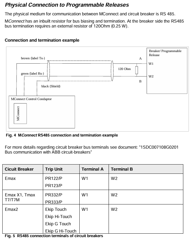
Communication interface: MConnect is connected to the circuit breaker through RS485 bus, with built-in bus bias and terminal resistance; An external 120 Ω (0.25W) terminal resistor is required on the circuit breaker side to ensure communication stability.
2. Software requirements
Basic version: MConnect requires a basic version of 7.6 or higher to fully support the functionality of MNS iS V7.6.
Auxiliary tools: Parameter settings need to be done in conjunction with MNavigate (Configuration and Management Tool), and some functions can be found in the MNavigate help documentation (such as hardware option usage).
Circuit breaker integration solution
The circuit breaker is the core component of the MNS iS cabinet, and MConnect achieves its monitoring and control through the following methods:
1. Supported circuit breakers and programmable release devices
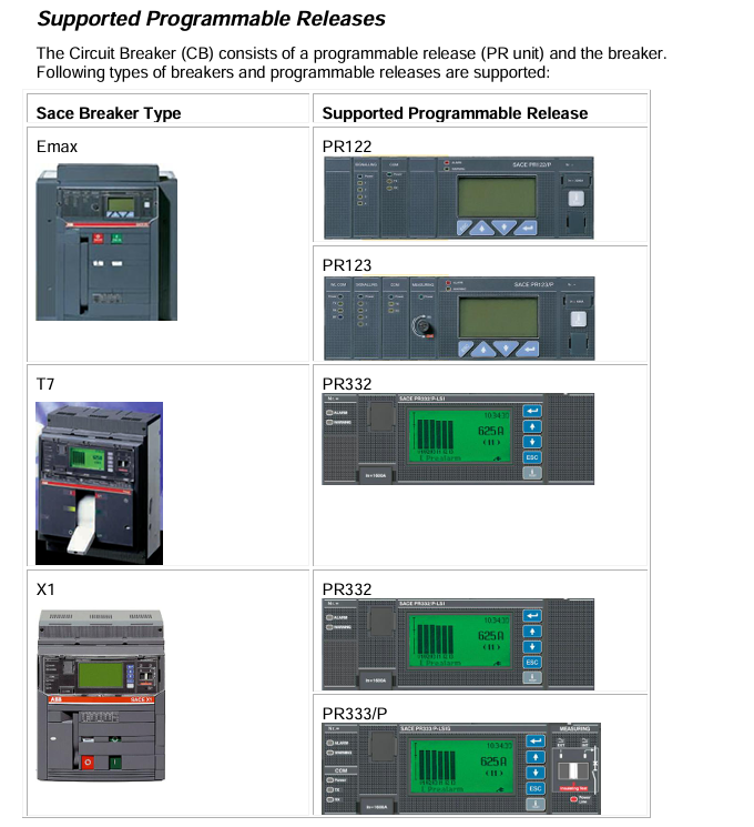
Remarks on Programmable Release Devices (PR Units) Supported by Circuit Breaker Types
Emax PR122/P, PR123/P classic series, corresponding to PR12x series release
Emax X1, Tmax T7/T7M PR332/P, PR333/P upgrade series, corresponding to PR33x series release
Emax2 Ekip Touch, Ekip Hi Touch, Ekip G Touch, Ekip G Hi Touch intelligent series, supporting richer state and data collection
2. Communication architecture and connections
Communication role: MConnect serves as the Modbus RTU master and communicates point-to-point with the programmable release of the circuit breaker (Modbus slave) through RS485; At the same time, as a gateway, it communicates with MLink through the internal "Switchgear Bus" (10Base-T Ethernet) of MNS iS.
System limitation: Following the MNS iS design rules, each MLink can connect up to 60 devices (including MConnect and MControl), distributed in up to 7 cabinets.
Physical connection: The RS485 bus adopts a three wire system (A/W1, B/W2, shielded wire), and the terminal definitions of different circuit breakers are unified (for example, the A/B terminals of Emax and Emax2 are all W1/W2). Please refer to the document "1SDC007108G0201" for details.
3. Configure parameters
The Modbus interface parameters of MConnect need to be consistent with the circuit breaker release, and the parameter settings are as follows:
Parameter optional range, default value description
Slave Address 2-247 247 needs to be configured the same as the PR unit of the circuit breaker
Baudrate rate 9600/19200 bps 19200 bps communication rate, needs to match PR unit settings
Protocol parity check 1 stop bit, odd parity check 1 stop bit, no parity check 2 stop bit, no parity check 1 stop bit, even parity check 1 stop bit. The format of the data check and stop bit should match the PR unit
Attention: The MConnect main site address is fixed at 1 and cannot be modified by users; Only supports "point-to-point" communication and does not support multiple bus slaves.
Data and Command Interaction
The document provides a detailed definition of data collection (status, measurement values, alarm/trip information) and control commands for MConnect and two types of release devices (PR12x/PR33x, Ekip). The core content is as follows:
1. PR12x/PR33x series release
(1) Status data (32-bit unsigned number, Motorola byte order)
Device status bits: There are a total of 16 bits, with key bits meaning "open (Bit0), closed (Bit1), tripped (Bit2), undefined (Bit3), discharged (Bit4)", and the remaining bits reserved (set to 0).
Extended Status Flag: Contains 8 types of flags, including State 2-9, covering alarm/trip (such as "any alarm" and "circuit breaker trip"), operating mode (local/remote), communication status (no communication on local bus), programming status (successful/failed programming), etc. Each type of flag is a 16 bit unsigned number (UWORD).
(2) Measurement value
Covering over 20 electrical parameters such as current, voltage, power, frequency, and energy, examples are as follows:
Measurement item data type unit invalid value explanation
L1 phase current (effective value) ULONG (unsigned long integer) A 0xffffffff current displays 0 when<minimum value, and displays maximum value when>maximum value
Line voltage V12 (effective value) UWORD-10 (10 times unsigned short integer) V 0xffff displays 0 when voltage<minimum value, and displays maximum value when voltage>maximum value
Total active power (signed) LONG_10 (10 times integer) kW 0x7ffffffff Display 0 when power<minimum value, display ± maximum value when out of range
Frequency UWORD_10 (10x unsigned short integer) Hz 0xffff: When the frequency is less than the minimum value, the minimum value is displayed, and when it is greater than the maximum value, the maximum value is displayed
Total active energy (signed) LONG kWh - cumulative energy value, supporting forward/reverse metering
(3) Alarm and trip information
By defining the STATE 4-6 (alarm) and STATE 8-9 (trip lock) flag bits, it covers over 30 abnormal scenarios such as "harmonic distortion exceeding 2.1", "contact wear alarm", "overvoltage trip", "hardware fault trip", etc. Each scenario corresponds to a specific bit (setting 1 indicates triggering).
2. Ekip series release (Emax2 specific)
(1) Status and measurement values
Status difference: The device status bit only retains "disconnected (Bit0), closed (Bit1), tripped (Bit2), undefined (Bit3)", and the remaining bits are reserved; The extended state is divided into four categories: global state (such as circuit breaker closure/isolation), timing state (such as L/S/G timing triggering), trip state (such as overload trip), and warning/alarm state (such as sensor error), covering more detailed intelligent monitoring scenarios.
Measurement value expansion: Added parameters such as "RC current (external grounding current)", "power factor (in kiloparts)", "PT100 temperature", etc., with data types compatible with PR12x/PR33x.
(2) Additional information collection
Support the full lifecycle data of circuit breakers, such as "Circuit Breaker Serial Number (16 bit ASCII)", "Installation Date/Last Maintenance Date (seconds from December 31, 1999)", "Operation Times (Opening Count)", "Contact Wear Percentage (0-65000 corresponds to 0% -100%)", etc., for easy maintenance and management.
3. Control commands (universal)
Only when the circuit breaker release is manually switched to "remote mode" (password required), the following commands can be sent through the MLink fieldbus:
Command function
CB Close Circuit Breaker Close
CB Open circuit breaker disconnected
CB Reset Circuit Breaker Reset
Trip Reset resets the trip records stored in the release device
Wink Toggle Command Circuit Breaker Identification (Tripper Display Flashing)
NOP no operation (no action)
4. Data validity (quality code)
Identify data validity through "QualityCode1" and "QualityCode2" (32-bit unsigned numbers):
Bit=0: Data is valid; Bit=1: Invalid data.
QualityCode1 covers measurement values (such as current, voltage, power), while QualityCode2 covers status indicators (such as alarm, trip) and equipment information (such as serial number, rated current).
Circuit breaker type decoding
The document provides decoding tables for two types of circuit breakers (TAB_CB.TYPE, TAB_CB.TYPE_33x), and specifies the specifications of the circuit breakers through a "numerical model" mapping. The example is as follows:
Decoding type, numerical circuit breaker model, numerical circuit breaker model
TAB_CB-TYPE (Emax series) 0 E1B800/3P 1 E1B800/4P
28 E2S800 / 3P 29 E2S800 / 4P
88 E4S4000 / 3P 89 E4S4000 / 4P
TAB_CB-TYPE_33x (Tmax/X1 series) 0 T7S800/3P 1 T7S800/4P
30 X1B800 / 3P 31 X1B800 / 4P
60 T7H1200 / 3P 61 T7H1200 / 4P
Note: "3P/4P" in the model indicates 3 poles/4 poles, and numbers (such as 800, 1200) indicate specifications related to rated current.
- OMRON
- ABB
- General Electric
- EMERSON
- Honeywell
- HIMA
- ALSTOM
- Rolls-Royce
- MOTOROLA
- Rockwell
- Siemens
- Woodward
- YOKOGAWA
- FOXBORO
- KOLLMORGEN
- MOOG
- KB
- YAMAHA
- BENDER
- TEKTRONIX
- Westinghouse
- AMAT
- AB
- XYCOM
- Yaskawa
- B&R
- Schneider
- KONGSBERG
- NI
- WATLOW
- ProSoft
- SEW
- ADVANCED
- Reliance
- TRICONEX
- METSO
- MAN
- Advantest
- STUDER
- DANAHER MOTION
- Bently
- Galil
- EATON
- MOLEX
- DEIF
- B&W
- ZYGO
- Aerotech
- DANFOSS
- Beijer
- Moxa
- Rexroth
- Johnson
- WAGO
- TOSHIBA
- BMCM
- SMC
- HITACHI
- HIRSCHMANN
- Application field
- XP POWER
- CTI
- TRICON
- STOBER
- Thinklogical
- Horner Automation
- Meggitt
- Fanuc
- Baldor
- SHINKAWA
- Other Brands
- UniOP
- KUKA
- Iba
- Beckhoff
- ADLINK
-
 Sigmatek Wiring Board V2 DIAS 05-250-023
 -
 Sigmatek CP102 20-004-102 S-DIAS CPU Module
 -
 SIGMATEK SLIDES CNC 115 Module
 -
 SIGMATEK DCC080 05-700-080-2 Control Module
 -
 SIGMATEK MDD 121 Drive Axis Module
 -
 SIGMATEK CIO011 C-DIAS Multi I/O Module
 -
SIGMATEK CIV512 Servo Drive
-
 SIGMATEK CM5V020 12-250-021-K Wiring Module
 -
 SIGMATEK CIO011 12-013-011 Multi I/O Module
 -
 SIGMATEK 01-450-031 C-IPC Industrial Computer
 -
 SIGMATEK AKM24D-ANBNGBB0 Servo Motor
 -
 DEMAG NC4 LP0001289.03 Control Module
 -
 Sigmatek ETEK Industrial PC C-IPC with Option Module
 -
 Sigmatek AO081 20-010-081 Analog Output Module
 -
 Sigmatek CNC 031 Positioning Module
 -
 Sigmatek CP731-K 20-004-731-K CPU Module
 -
Sigmatek MDD 3320-JR-A Drive Module
-
 Sigmatek PM Servo Motor AKM52K-ANC2GBB0
 -
Sigmatek MDP 101 09-403-101 Power Module
-
 Sigmatek S-SLIDES AO046 Analog Output Module
 -
 Sigmatek ICA111 20-102-111 Interface Module
 -
 SIGMATEK DCP646 Module 05-004-646
 -
 SIGMATEK SDI101 Digital Input Module 20-891-101
 -
 SIGMATEK S3330-2 Directional Gyro Altitude Instrument
 -
SIGMATEK MDP102-1 Controller
-
 SIGMATEK SMT 01-230-321 Touch Screen
 -
SIGMATEK Krauss Maffei PC301-K 01-310-301-K Industrial PC with 8GB SSD
-
 SIGMATEK ETT731 01-230-731 Built-in Touch Terminal
 -
 SIGMATEK CIV521 Control Module
 -
 SIGMATEK DME 128 Module 05-005-128
 -
 SIGMATEK SCP111-S 20-890-111-S S-DIAS Safety CPU Module
 -
 Sigmatek SCP111 S-DIAS Safety CPU
 -
 Sigmatek CRIF081 Interface Module
 -
Sigmatek CP112-1 S-DIAS CPU Module
-
 Sigmatek MDD121-L DIAS Drive Axis Module
 -
 Sigmatek C-IPC 01-450-024 Industrial PC
 -
Sigmatek SDD215-23 SLIDES Drive
-
 Sigmatek DPS001 DIAS System Components
 -
Sigma-Tek 4000B-30 Directional Gyro
-
 Sigmatek SDD340-46 SDD Series Drive
 -
 Sigmatek CEZ221 Euromap67 I O Module
 -
 SIGMATEK VI021 Interface Module
 -
SIGMATEK CP731-K Control Module
-
SIGMATEK Krauss Maffei PC321-K Industrial PC
-
SIGMATEK ET322 Operator Terminal
-
SIGMATEK CP102 Control Module 24VDC
-
SIGMATEK SRO021 Relay Output Module
-
 SIGMATEK DCP640 DIAS Central Unit
 -
 SIGMATEK MDD 121 Drive Axis Module
 -
SIGMATEK AI043 Analog Input Module
-
 ENOTEC OXITEC 5000 SME-53310000 Oxygen Analyzer
 -
SIGMATEK Krauss Maffei PC301-K 01-310-301-K Industrial PC
-
 SIGMATEK SDD310-23 VARAN Servo Drive
 -
 SIGMATEK CDM 163 and CIC 011 C-DIAS Input Modules
 -
SIGMATEK MDP 101-1 Power Module
-
 SIGMATEK CM5V020 Wiring Circuit with CTMS020
 -
SIGMATEK CCP521 C-DIAS Processor Module
-
 SIGMATEK MDP 101-K Power Module
 -
SIGMATEK ETEK C-IPC 733MHz VIA Eden 7000
-
 SIGMATEK DCP 643 DIAS PLC CPU Module
 -
SIGMATEK TAE121 12-200-121 Operator Terminal
-
Sigmatek TMS012-T Injection Moulding Technology Module
-
Sigmatek MDD 121-1 Controller
-
Sigmatek CDM167 Module
-
Sigmatek DCP082 DIAS Central Unit
-
 Sigmatek ETT731 Built-In Terminal Touch
 -
Sigmatek CCP521 C-DIAS Processor Module
-
 Sigmatek Krauss Maffei PC301-K Control Cabinet PC
 -
 Sigmatek CIC-21 C-DIAS CAN Module
 -
Sigmatek CIO-011 Multi I O Module
-
Sigmatek 01-450-152D C-IPC 152 Industrial PC
-
SIGMATEK 01-450-024 C-IPC 128MB VIA 733MHz
-
SIGMATEK CCL-081 C-DIAS Processor Module
-
 SIGMATEK CP311 20-004-311 Module
 -
 SIGMATEK EP00000262 SLIDES MIDI I O-V3 Controller
 -
SIGMATEK TMS012-T Slides Technology Module
-
SIGMATEK MDD111-1 Drive Axis Module
-
 SIGMATEK MDP101-1 PLC Module
 -
 SIGMATEK CP111 S-DIAS Processor Module
 -
 DEMAG ErgoControl Sigmatek NC4 Display Unit
 -
 SIGMATEK DCP642 Module
 -
 Sigmatek Demag NC4 9617.067.03 Control Module
 -
Sigmatek DCP 643 Central Processing Unit
-
Sigmatek VI 021 S-SLIDES VARAN Interface Module
-
 Sigmatek SDD340-46 Servo Drive 14kVA
 -
Sigmatek DSI021 Slide Siemens Interface
-
Sigmatek CCL912 C-SLIDES CPU PSU Module
-
Sigmatek ETV1521 VARAN Control Panel
-
 Sigmatek ET322 Operator LCD Terminal
 -
 Sigmatek MDD1111 DIAS Drive Module
 -
Sigmatek CAM123 Module
-
 SIGMATEK CP111 VARAN Ethernet Controller
 -
 SigmaTek MDD 111 Axle Module
 -
SIGMATEK CIO013 C-DIAS I O Module
-
 SIGMATEK AKM52K-ANC2GBB0 Servomotor 640VDC
 -
 SIGMATEK ETT321 01-230-321 Touch Screen
 -
 SIGMATEK NC4Kompakt 01-250-010-D Safety Controller
 -
 SIGMATEK CIO011 C-DIAS Multi I O Module
 -
SIGMATEK MDD 121-1 Drive Axis Module
-
SIGMATEK CDM163 Control Module
-
Sigma-Tek 4000HR-3 Heading Reference Directional Gyro
-
Sigmatek DIAS DAI 883 Analog Input Module
-
Sigmatek 0332.554.03 Printed Circuit Board Card
-
 Sigma Tek 5000B-36 Attitude Gyro 8130
 -
Demag NC4 0332.554.03 Sigmatek Control Board
-
Sigmatek IPC Pentium 300 CF Industrial PC
-
Sigmatek MDP 102 PLC Module
-
 Sigmatek DTO163 Digital Output Module
 -
 Sigmatek PCT151 Touch IPC 15 Panel and I-PC C300
 -
Sigmatek CCL911 CD Processor Module
-
Sigmatek SCP011 S-DIAS Safety CPU Module
-
Sigmatek SE051 Network Splitter Module
-
Sigmatek CIO011 C-DIAS I O Module
-
 Sigmatek SE051 Ethernet Splitter
 -
 Sigmatek CCL911 CD Processor Module
 -
Sigmatek SDD310-4 DIAS Drive 14kVA
-
Sigmatek CTMS020 C-DIAS Technology Module
-
Sigmatek CTMS020 CD Technology Module
-
Sigmatek CTO167 C-SLIDES Digital Output Module
-
Sigmatek C-IPC 152 Industrial PC
-
 Sigmatek SDD310-4 SLIDES Drive 310
 -
SIGMATEK MDP 102-1 DIAS Power Module
-
 SIGMATEK SCP111 S-DIAS Safety CPU Industrial
 -
SIGMATEK CAO081 Analog Output Module
-
SIGMATEK DCC080L Control Module
-
 SIGMATEK MDP101-1 Power Module
 -
SIGMATEK SCP111 S-DIAS Safety CPU
-
 SIGMATEK PC325-K Industrial PC


