
YASKAWA Machine Controller MP2000 Series
Adaptive controller: MP2000 series machine controller (MP210M, MP2200, MP2300, MP2500MD)
Core functions: Support multi protocol industrial communication, data transmission between devices, engineering debugging and maintenance, and adapt to various interfaces such as RS-232C, Ethernet, DeviceNet, etc
YASKAWA Machine Controller MP2000 Series
Core positioning
Applicable products: JAPMC-CM23 model communication module, including 6 sub models: 218IF-01, 218IF-02, 217IF-01, 260IF-01, 261IF-01, 215AIF-01
Adaptive controller: MP2000 series machine controller (MP210M, MP2200, MP2300, MP2500MD)
Core functions: Support multi protocol industrial communication, data transmission between devices, engineering debugging and maintenance, and adapt to various interfaces such as RS-232C, Ethernet, DeviceNet, etc
Hardware specifications and installation configuration
1. Core parameters of the module
Module model, communication interface, key specifications, protection level, weight
218IF-01 RS-232C+Ethernet (10Base-T) serial port up to 19.2kbps; Ethernet 10Mbps, TCP/UDP protocol IEC IP00 85g
218IF-02 RS-232C+Ethernet (10Base-T) supports Ethernet (LP) mode, with larger engineering message size IEC IP00-
217IF-01 RS-232C+RS-422/485 serial port up to 19.2kbps, half duplex/full duplex optional IEC IP00-
260IF-01 RS-232C+DeviceNet supports DeviceNet master-slave communication, explicit/implicit message IEC IP00-
261IF-01 RS-232C+PROFIBUS compatible with PROFIBUS protocol, industrial bus communication IEC IP00-
215AIF-01 RS-232C+MPLINK/CP-215 supports token passing mechanism and link communication function IEC IP00-
2. Installation and wiring requirements
Environmental conditions: working temperature ≤ 55 ℃, no corrosive gases, vibration ≤ 9.8m/s ², avoid direct sunlight and condensation
Installation specifications: The module needs to be aligned with the guide rail and inserted into the controller slot, with a bolt tightening torque of 2.94N · m. Unused slots need to be equipped with dust covers
Wiring requirements: The distance between the control signal and the power line should be ≥ 30cm, and the grounding wire should be as short as possible (single point grounding); RS-422/485 adopts a 4-wire wiring system and requires 120 Ω terminal resistors to be connected at both ends
Port protection: The FG terminal needs to be reliably grounded, and the cable shielding layer should be connected to the equipment casing to avoid electromagnetic interference
Communication mode and protocol system
1. Three major communication modes
Message communication: Triggered through MSG-SND/MSG-RCV functions, supporting master-slave data exchange and adapting to multiple protocols (MEMOBU, MELSEC, etc.)
Engineering Communication: Used for debugging communication between MPE720 programming software and controller, supporting interfaces such as serial port and Ethernet
Link communication: only applicable to 215AIF-01 module, automatically timed transmission of preset I/O data, based on token passing mechanism
2. Core Communication Protocol
Protocol Name Applicable Interface Core Features Application Scenarios
MEMOBU serial/Ethernet YASKAWA standard protocol, master-slave communication, supports coil/register read/write data transmission between devices of the same brand
Extended MEMOBU Ethernet/MPLINK Extended MEMOBU, supporting up to 508 words of data transmission for large data volume industrial communication
MELSEC serial/Ethernet compatible with Mitsubishi MELSEC PLC, supporting communication between CPUs, buffering communication, and cross brand PLC interconnection
MODBUS/TCP Ethernet Industrial General Protocol, client/server mode, cross vendor device compatible communication
OMRON serial port compatible with Omron SYSMAC PLC, Host Link mode Omron device integration
Non protocol full interface without preset protocol, directly transmitting continuous register data custom protocol scenario
DeviceNet 260IF-01 module device network protocol, supports explicit/implicit message industrial bus device interconnection
Software Configuration and Programming Implementation
1. Basic configuration process
Communication Manager Settings: Configure logical ports (up to 16), select port types such as serial/Ethernet/CP-215, and set parameters such as baud rate and IP address
Self configured execution: triggered by the DIP switch or MPE720 software of the controller, automatically identifies the module and generates a configuration file
MPE720 parameter settings: Start programming software and configure project communication parameters (logical port, IP address, protocol type)
Transmission definition configuration: Set transmission protocol, master-slave mode, data address, timeout time, etc. for different modules
2. Core programming functions
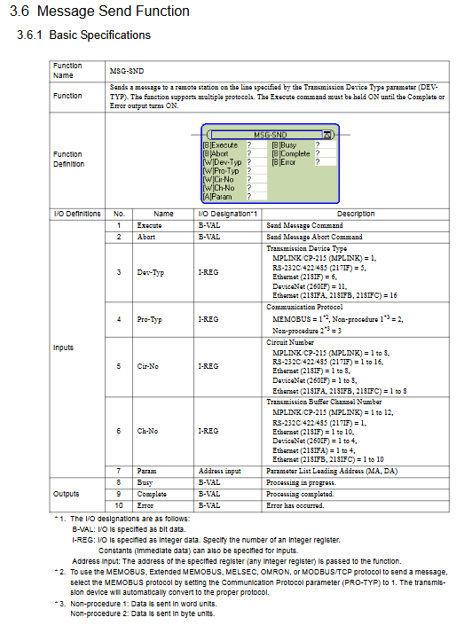
MSG-SND (Message Sending Function): sends data to remote devices, supports multi protocol selection, core parameters include execution bit, device type, protocol type, circuit number, parameter list address
Input parameters: Execute (start send), Abort (interrupt send), Dev Typ (device type), Pro Typ (protocol type), etc
Output parameters: Busy (processing), Complete (sending completed), Error (sending error)
MSG-RCV (Message Reception Function): Receive remote device data, support automatic/manual reception switching, core parameters correspond to the sending function
Support data offset storage, receive range limitation, and can monitor communication status and error messages
3. Programming Example Scenarios
218IF-01 Ethernet Communication: Master (IP 192.168.1.2) and Slave (IP 192.168.1.3) transmit 100 word data via UDP using Extended MEMOBU protocol
MELSEC PLC connection: Read the D0000-D0063 register data of Mitsubishi PLC, store it in controller MW10000-MW10063, and automatically convert it through MELSEC protocol
Non process protocol communication: Unidirectional transmission of 254 word continuous register data, no response mechanism, suitable for custom protocol interaction
Detailed operation of each module (taking 218IF-01/02 as an example)
Module 218IF-01
Interface specifications: RS-232C (9-pin D-sub)+Ethernet (RJ-45), supporting TCP/UDP protocols
Key settings:
Ethernet parameters: IP address (default 192.168.1.1), subnet mask 255.255.255.0, port numbers 256-65535
Serial port parameters: data bits 7/8, parity bits (odd/even/none), stop bits 1/2, baud rate 9600/19200bps
Communication example: Ethernet connection between modules, Master reads Slave's MW00000-MW00063 data through MSG-SND and stores it locally in MW01000-MW01063
Module 218IF-02
Core advantages: Supports Ethernet (LP) mode, larger engineering message size, faster communication speed
Unique settings: Ethernet (LP) is selected as the logical port, 9999 is set as the engineering port, and the IP address is compatible with 218IF-01
Connection example: Ethernet connection with a personal computer, engineering debugging through MPE720 software, supporting high-speed data transmission
Maintenance and troubleshooting
1. Key points for regular maintenance
Daily inspection: Terminal fastening, cleaning of heat sink (compressed air blowing), no damage to cables
Component replacement cycle: cooling fan 2-3 years, smoothing capacitor 5 years, motor bearing 2 years/12000 hours, fuse 10 years
Safe operation: Before maintenance, the power must be cut off and wait for the capacitor to discharge (CHARGE LED to turn off); Use insulated tools and do not touch CMOS components
2. Common troubleshooting
Common causes and solutions for fault phenomena
Communication timeout (ERROR light on) IP address conflict, port number error, transmission parameter mismatch check network configuration, unified baud rate/checksum and other parameters
Data transmission error: loose wiring, ungrounded shielding layer, electromagnetic interference: re tighten terminals, optimize wiring (away from power lines), and rectify grounding
Hardware malfunction (ERR light flashing) ROM/RAM error, module not recognized, perform self diagnostic test, replace control board, reinstall module
Ethernet connection failure, network cable damage, switch failure, IP configuration error. Replace the network cable, check the switch status, and confirm that the IP is in the same network segment
3. Fault reset method
Trigger reset input signal, press the [RESET] button on the operator, turn off the main circuit power and restart
Reset premise: eliminate the cause of the fault and turn off the external operation command (FWD/REV/ORT)
- OMRON
- ABB
- General Electric
- EMERSON
- Honeywell
- HIMA
- ALSTOM
- Rolls-Royce
- MOTOROLA
- Rockwell
- Siemens
- Woodward
- YOKOGAWA
- FOXBORO
- KOLLMORGEN
- MOOG
- KB
- YAMAHA
- BENDER
- TEKTRONIX
- Westinghouse
- AMAT
- AB
- XYCOM
- Yaskawa
- B&R
- Schneider
- KONGSBERG
- NI
- WATLOW
- ProSoft
- SEW
- ADVANCED
- Reliance
- TRICONEX
- METSO
- MAN
- Advantest
- STUDER
- DANAHER MOTION
- Bently
- Galil
- EATON
- MOLEX
- DEIF
- B&W
- ZYGO
- Aerotech
- DANFOSS
- Beijer
- Moxa
- Rexroth
- Johnson
- WAGO
- TOSHIBA
- BMCM
- SMC
- HITACHI
- HIRSCHMANN
- Application field
- XP POWER
- CTI
- TRICON
- STOBER
- Thinklogical
- Horner Automation
- Meggitt
- Fanuc
- Baldor
- SHINKAWA
- Other Brands
- UniOP
- KUKA
- Iba
- Beckhoff
- ADLINK
-
 Sigmatek MDD111-1 DIAS Drive Axis Module
 -
 Sigmatek DKL042 05-024-042 Terminal Module
 -
 Sigmatek DM822 Control Module
 -
 Sigmatek CDM167 12-008-167-O Module
 -
 Sigmatek TAE151 Touch Display Unit
 -
 Sigmatek DCC041 SLIDES Module 05-700-041-D
 -
 Sigmatek AKM65M-ANC2GBB0 PM Servo Motor
 -
 Sigmatek ETT221 01-230-221 Operator Terminal
 -
 Sigmatek SLIDES DAM 124 Analog Module
 -
Sigmatek AKM31C-ANCNGBB0 Servo Motor
-
 Mannesmann Demag Sigmatek CP626 Central Unit
 -
 SIGMATEK 0332.554.03 Board 371071000154
 -
 SIGMATEK 12-250-021 Base Plate Back Panel CM5V020
 -
 SIGMATEK DM162 S-DIAS Digital Mix Module
 -
 DEMAG ERGOTECH 061 381 66 Sigmatek 9842.243.02 Circuit Board
 -
 SIGMATEK CP313-1 PLC Module
 -
Sigmatek ETV0551-2 VARAN Touch Terminal
-
 Sigmatek SDM 081 FS S-Dias Safety Module
 -
 DEMAG 05-250-023 Ergotech Motherboard with Sigmatek TMS012
 -
Sigmatek CM5V020 12-250-023-K Wiring Base
-
 Sigma Tek 5000B-37 Attitude Gyro Indicator
 -
 Sigmatek SDD120-2 DIAS Drive
 -
 Sigmatek CME221 Memory Module
 -
 Sigmatek DCP640 DIAS Central Unit
 -
 Sigmatek STO040 Safety Output Module
 -
Sigmatek CET281 Control Panel
-
 Sigmatek CIPC LX800 Demag NC5 CPU
 -
 Sigmatek DKL093 05-024-093 Terminal Module
 -
 Sigmatek AI088 20-009-088 Analog Input Module
 -
Sigmatek CAI888 Analog Input Module
-
SIGMATEK CCA021 12-025-021 Analog Output Module
-
SIGMATEK 1104.579.05 Control Module
-
SIGMATEK SDI100 Digital Input Module
-
 SIGMATEK C-IPC 256MB LX800 Compact Dias
 -
 SIGMATEK 9423.090.02 Control Module
 -
SIGMATEK C-IPC 256 Power Supply 148498
-
 SIGMATEK CAI025 Analog Input Module
 -
 SIGMATEK CTO166 Digital Output Module
 -
 SIGMATEK CP112 20-004-112 Processor Module
 -
SIGMATEK CAI887 12-009-887 Safety Module
-
 Sigma-Tek 4000B-31 Directional Gyro 1U262-002-42
 -
Sigmatek C-IPC 256MB LX800 IPC Controller
-
Sigmatek C-IPC 01-450-031 Industrial PC LX800
-
Sigmatek C-IPC 256 Industrial PC Controller
-
Sigmatek CCP-531 PLC Processor Module
-
Sigmatek CDI163 Digital Input Module
-
 Sigmatek ETV0501 VARAN Terminal 12-230-0501
 -
 Sigmatek CTMS020 C-DIAS Technology Module
 -
 Sigmatek CIV512 VARAN Switch Module
 -
 Sigmatek HU011 20-080-011 Interface Module
 -
SIGMATEK SLIDES DAM 124 Module
-
 SIGMATEK C-IPC 161 01-450-161L Industrial PC
 -
SIGMATEK C-IPC 128MB VIA 733MHz 01-450-024-K
-
 SIGMATEK 12-780-012 R8-IPC Geode LX800 Module
 -
SIGMATEK CAM124 Analog Module
-
 SIGMATEK S1 032-8AF61-R4 EZ Servo Motor
 -
 SIGMATEK CTO163 Digital Output Module
 -
 SIGMATEK CCP082 12-004-082 Processor Module
 -
 SIGMATEK CRCH081 C-DIAS Temperature Module
 -
 SIGMATEK PC322-K 01-310-322-K Industrial PC
 -
SIGMATEK SDD310-2 Servo Drive
-
 SIGMATEK AI084 Analog Input Module
 -
SIGMATEK CRCH081 12-752-081 Temperature Module
-
Sigma-Tek 5000L-4 Attitude Gyro 1U284-001-3
-
 SIGMATEK CM5V020 12-250-023-K Wiring Module
 -
Sigma-Tek 4000H-6 Directional Gyro IU262-035-7
-
 SIGMATEK Dias DCP160 05-004-160 Processor Module
 -
SIGMATEK 0147.395.02 Control Module
-
SIGMATEK A1084 Control Module
-
SIGMATEK DI200 20-006-2000 Digital Input Module
-
Sigmatek DNC115 Encoder Module
-
 Sigmatek DAM122 05-017-122 Analog Module
 -
Sigmatek 9802.289.01 Control Board TA71 Display
-
Sigmatek TO127 20-007-127 Digital Output Module
-
Sigmatek DNC031 05-011-031 Digital Module
-
Sigmatek VI022 20-003-022 Interface Module
-
Sigmatek CAI085 Analog Input Module
-
 Sigmatek CP111 S-DIAS CPU Module
 -
Sigmatek CTMS030 Krauss Maffei Module
-
 Sigmatek CAM123 Control Module
 -
 Sigmatek TAE732-P 01-240-732-P Touch Display Unit
 -
Sigmatek MDM021 Digital Mixed Module
-
Sigmatek DCP642 DIAS Central Unit
-
 Sigmatek CST022 12-014-022 C-DIAS Module
 -
 Sigmatek SRO021 20-893-021 Safety Relay Output
 -
 Krauss Maffei MC5 Control System Sigmatek
 -
 Sigmatek DC061 Module 18-24VDC 300mA
 -
 Herrmann EVT0855 Ultrasonic Welder Touch Panel
 -
Sigmatek CIV521 Control Module 1.4A 2W
-
Sigmatek DDI61 05-006-161 Digital Input Module
-
SIGMATEK ETT312-E Touch Terminal 01-230-312
-
Cessna S3326-1 Sigma Tek 5000B-67 Gyro 1U149-015-9
-
SIGMATEK PS101 Power Supply Module
-
SIGMATEK 0332.554.03 Control Module 371071000154
-
 SIGMATEK ETT312-E Touch Terminal 01-230-312
 -
SIGMATEK CDM163 Control Module
-
 SIGMATEK VSV046 16-023-046 Module
 -
SIGMATEK AM221 20-017-221 Analog Module
-
SIGMATEK CTS051 12-053-051 Control Module
-
SIGMATEK AM221 20-017-221 Analog Module
-
Sigmatek CSDI161 12-891-161 Safety Input Module
-
Sigma Tek 4000C-1 Directional Gyro Indicator
-
Sigmatek ETV0501 12-230-0501 VARAN Terminal
-
Sigmatek DDM165 SLIDES Module
-
Sigmatek N100 20-011-100 Control Module
-
Sigmatek AKM54K-ANC2R-B0 PM Servo Motor
-
Sigmatek CTO166 Digital Output Module
-
Sigmatek CP212-K 20-004-212-K CPU Module
-
Sigmatek CDI161 Digital Input Module
-
Sigmatek DCC080 05-700-080-2 Control Module
-
 SIGMATEK SCP011 S-DIAS Safety CPU
 -
SIGMATEK SCP011 S-DIAS Safety CPU
-
SIGMATEK SRO022 Relay Output Module
-
SIGMATEK MDD 121 Drive Axis Module
-
SIGMATEK DSI021 SLIDES Siemens Interface
-
SIGMATEK DIAS DCP161 Module 05-004-161
-
 Sigmatek ETT312 Built-in Touch Terminal
 -
SIGMATEK DCP 643 DIAS Controller System
-
SIGMATEK CIO021 Multi I/O Module
-
SIGMATEK CTMS020 Control Module
-
 Sigmatek CME 221 Memory Module
 -
Sigmatek 0420.615.01 Control Board
-
Sigmatek CP111 20-004-111 CPU Module
-
Sigmatek 9405.065.03 Control Board
-
Sigmatek ETEK 01-450-032-K C-IPC 256MB Industrial PC
-
Sigmatek CTO163 12-007-163 Safety Output Module
-
Sigmatek TO081 20-007-081 Digital Output Module
-
 Sigmatek SI021 20-022-021 Safety Input Module


