
YOKOGAWA MY600 Digital Insulation Resistance Tester
YOKOGAWA MY600 Digital Insulation Resistance Tester
Product positioning and core functions
MY600 is a compact digital insulation resistance tester designed to measure the insulation resistance of electrical equipment or circuits. It supports voltage measurement (AC/DC) and low resistance on/off inspection, and is portable, high-precision, and adaptable to multiple scenarios. It is widely used in fields such as power equipment maintenance, electrical installation acceptance, and industrial circuit testing.
Packaging and Accessories
1. Standard accessories (included with the product)
After opening the box, it is necessary to confirm that the following accessories are intact. If they are missing or damaged, please contact the Yokogawa distributor:
Accessory Name Model/Part Number Quantity Usage
Portable case 93045 1 for storing instruments and accessories, easy to carry
Line probe with remote switch 98008 1 connected to LINE terminal for line side measurement
Grounding probe group 98009 1 is connected to the EARTH terminal for measuring the grounding side
Shoulder strap 99018 1 hanging instrument, supports dual hand operation
Alkaline dry battery -4 instrument power supply (AA alkaline battery recommended)
User manual set IM MY600-01EN/92Z1/00C01C01-01Z2/PIM113-01Z2, each containing multilingual instructions and global contact information
2. Optional accessories (to be purchased separately)
According to the requirements of the measurement scenario, it is necessary to ensure that the accessories meet the rated parameters of the instrument:
Accessory Name Model/Part Number Usage
USB communication adapter 91030 is used to connect to a PC and transfer measurement data from memory
Hook probe tip 99012 replaces standard probe, suitable for special wiring scenarios
Long probe tip 99013 deep into narrow spaces for measurement, expanding measurement range
Safety regulations
1. Core safety warning (to avoid electric shock/equipment damage)
Laser and high voltage protection: When measuring insulation resistance, there is high voltage at the tip of the probe, and touching the probe or the tested circuit is prohibited; After measurement, wait for automatic discharge to complete(“ ⚠️” Symbol flashing+buzzing), then touch the circuit.
Measurement category restriction: The rated measurement category of the instrument is CAT III 600V, and it is prohibited to use it for CAT IV or main power circuits exceeding 600V; When the probe is paired with different accessories, the category is different (for example, 98008 with insulation cap is CAT III 600V, and without cap is CAT II 1000V).
Requirements for the tested equipment: Before measurement, the power supply of the DUT must be cut off, and the voltage measurement function must be used to confirm that there is no power before starting; Do not measure live circuits to avoid instrument damage or electric shock.
Equipment status check: If the instrument casing is damaged, the probe cable is exposed, or the battery compartment is damp, use is prohibited; After falling or colliding, it is necessary to contact the dealer for maintenance to avoid insulation protection failure.
2. Operation safety rules
Battery replacement: Before replacing, power off and remove the probe. It is forbidden to open the battery compartment during measurement; New batteries of the same type should be used to avoid mixing old and new/different models.
Environmental restrictions: Do not use in flammable gas, humid (with condensation) or outdoor rainy environments; Working temperature range -10~+50 ℃, storage temperature -20~+60 ℃, avoid direct sunlight.
Probe usage: Only Yokogawa designated probes can be used, damaged or aged probes should be replaced in a timely manner; Before connecting/disassembling the probe, it is necessary to disconnect it from the device being tested.
Core functions and operating procedures
1. Measurement mode and parameters
The instrument supports three core measurement modes, and the parameters and applicable scenarios for each mode are as follows:
(1) Voltage measurement (AC/DC automatic detection)
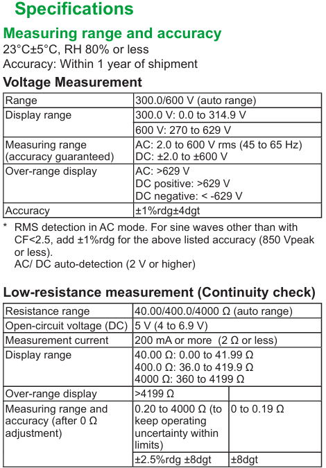
Range and Range: Automatic range (300.0V/600V), measurement range AC 2.0~600V (45~65Hz), DC ± 2.0~± 600V, over range display ">629V" (AC/positive DC) or "<-629V" (negative DC).
Accuracy: ± 1% reading ± 4 digits (23 ℃± 5 ℃, RH ≤ 80%), AC detected using true RMS, non sinusoidal (CF<2.5) requires an additional ± 1% error.
Operation steps:
Connect the line probe (98008) to the LINE terminal, and connect the ground probe (98009) to the EARTH terminal.
Set the range switch to "V/Ω" and connect the probes to the line side and ground side of the tested circuit.
No need to press the measurement switch, the instrument automatically detects AC/DC and displays the value (triggering a live warning when ≥ 30V:“ ⚠️” Blinking and buzzing.
(2) Insulation resistance measurement (core function)
Rated voltage and range: Supports six rated voltages of 50V/100V/125V/250V/500V/1000V, with automatic range switching (such as 1000V range of 4~4000M Ω), and a fixed value displayed for exceeding the range (such as>4199M Ω).
Key parameters:
Open circuit voltage: 100-110% of rated voltage.
Short circuit current: ≤ 1.5mA (1000V range) to ensure measurement safety.
Accuracy: First effective range (such as 1000V range 0.100~1000M Ω) ± 2% reading ± 2 digits; Second effective range (1001~4000M Ω) ± 5% reading.
Featured Features:
Automatic discharge: After measurement, keep the probe connected, and the instrument will automatically release the charge of the measured capacitor load. Before the discharge is completed“ ⚠️” Flashing and buzzing.
Pass/Tail judgment: A reference value (0.001~4199M Ω) can be set. When the measured value is ≥ the reference value, the backlight flashes green and "PASS", otherwise it flashes red and "FAIL".
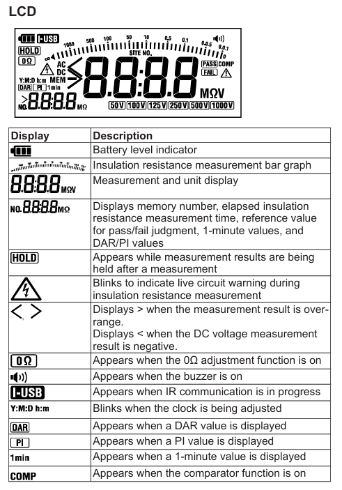
DAR/PI calculation: Automatically calculate the dielectric loss absorption ratio (DAR=1 minute value/15 second value) and polarization index (PI=10 minute value/1 minute value), ranging from 0.00 to 9.99, with ">9.99" displayed if out of range.
Operation steps:
Connect the probe, confirm that the tested device is powered off, and verify that there is no power using voltage measurement.
Turn the range switch to the corresponding rated voltage level (long press SELECT to switch between 125V/100V levels).
Connect the probe to the device under test, and simultaneously press the instrument's "measurement switch" and the probe's "remote switch" to start measuring (continuous measurement requires locking the measurement switch).
After the measurement is completed, wait for the automatic discharge to end before removing the probe.
(3) Low resistance measurement (on-off check)
Range and Range: Automatic Range (40.00 Ω/400.0 Ω/4000 Ω), Measurement Range 0.00-4199 Ω, Over Range Display ">4199 Ω".
Key parameters:
Open circuit voltage: DC 4~6.9V.
Measurement current: below 2 Ω ≥ 200mA, when the current is ≥ 200mA, a buzzer will sound to indicate on/off.
Accuracy: 0.20-4000 Ω± 2.5% reading ± 8 digits; 0~0.19 Ω± 8 digits (0 Ω calibration needs to be performed first).
Featured feature: 0 Ω calibration (can counteract probe and fuse resistance, up to 3 Ω), ensuring low resistance measurement accuracy.
Operation steps:
Turn the range switch to "V/Ω" and press SELECT to switch to low resistance mode.
Short circuit the probe, long press the "0 Ω ADJ" button to perform calibration (display "0.00 Ω" and light up the "0 Ω" indicator light).
Connect the probe to the tested circuit, press the measurement switch, and display the resistance value (beep when the current is ≥ 200mA).
2. Auxiliary functions
Backlight and LED lights: The illuminance sensor automatically detects the ambient brightness, automatically turns on the backlight and measurement point LED lights when dim, and automatically turns off after 2 minutes of inactivity; It can also be manually set to be normally off.
Automatic shutdown: Automatic shutdown after 10 minutes of inactivity (disabled during measurement or when the measurement switch is locked), with a warning beep before shutdown.
Clock settings: Year/month/day/hour/minute can be set, measurement data is automatically associated with timestamps, and there is a built-in lithium battery backup clock (with a lifespan of about 10 years).
Memory function: can store 1000 sets of measurement data (voltage/insulation resistance/low resistance), including DAR/PI, time, range and other information; Support data viewing and deletion (single/all), and transfer to PC through USB adapter.
System Settings and Data Management
1. Function configuration (long press SETUP to enter configuration mode)
Pass/Tail reference value: Set the judgment threshold for each voltage level, supporting preset values (such as default 0.5M Ω for 500V level) or custom values (0.001-4199M Ω).
Backlight/LED lights: Set to "ON" (automatic start stop) or "OFF" (normally off).
Buzzer: Set "ON" (live warning, discharge, on/off prompt) or "OFF" (turn off all beeps).
Clock calibration: Adjust the year/month/day/hour/minute to ensure accurate data timestamps.
2. Data management
Storage: When holding the measurement value, press the MemoRY button briefly to set the site number (SITE No.1/2, 0~99) and data number (automatically increasing) to complete the storage.
View: Press and hold the Memory button during standby time, select the data number using the directional keys, and view the measured values and station information.
Delete: When viewing data, select the number (or "ALL") and press ENTER to confirm the deletion (single or all).
Transmission: Connect to the PC via USB communication adapter (91030), install the driver, and export data using commands (refer to IM 91030-01EN manual).
Maintenance and repair
1. Daily maintenance
Battery management: When the battery level is low, the "battery icon" displays "empty" and needs to be replaced in a timely manner (4 AA alkaline batteries); Long term disuse requires removing the battery to avoid leaking and damaging the instrument.
Cleaning: Wipe the outer shell with a dry soft cloth, and do not use abrasives or solvents; The surface of the illuminance sensor needs to be kept clean to avoid affecting the automatic backlight/LED function.
Calibration cycle: It is recommended to calibrate once a year to ensure measurement accuracy. Calibration must be performed by Yokogawa certified personnel.
2. Fault handling and maintenance
Frequently Asked Questions:
Inaccurate measurement value: Check the battery level, probe connection, and perform 0 Ω calibration again for low resistance measurement.
Backlight/LED not on: Clean the illuminance sensor or manually confirm that the configuration mode is set to "ON".
Unable to store data: Memory is full (old data needs to be deleted), or the operation was not in the 'measurement value hold' state.
Maintenance restrictions: It is prohibited to disassemble the instrument by oneself (only battery replacement can open the battery compartment). For internal faults, please contact the Yokogawa dealer. Repairs involving safety insulation components require professional operation.
3. Disposal and Compliance
Equipment disposal: When disposing of equipment, local laws and regulations must be followed, and batteries (alkaline batteries and built-in lithium batteries) must be separated and classified for disposal.
Environmental Compliance: Compliant with EU RoHS Directive, WEEE Directive (prohibiting the mixing of household waste in EU regions), and EU Battery Directive (batteries must be recycled separately).
Product Specifications
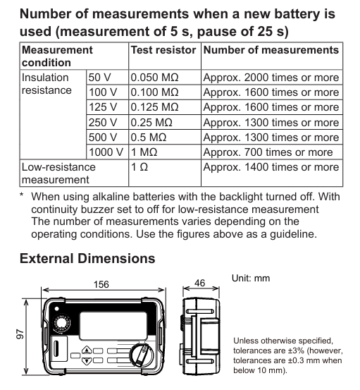
Appearance dimensions: 156 (W) × 46 (H) × 97 (D) mm, weight approximately 490g (including battery).
Factory default settings: such as Pass/Tail reference values for each voltage level (0.5M Ω for 500V level), default "ON" for backlight/buzzer, default clearing of memory, etc.
- OMRON
- ABB
- General Electric
- EMERSON
- Honeywell
- HIMA
- ALSTOM
- Rolls-Royce
- MOTOROLA
- Rockwell
- Siemens
- Woodward
- YOKOGAWA
- FOXBORO
- KOLLMORGEN
- MOOG
- KB
- YAMAHA
- BENDER
- TEKTRONIX
- Westinghouse
- AMAT
- AB
- XYCOM
- Yaskawa
- B&R
- Schneider
- KONGSBERG
- NI
- WATLOW
- ProSoft
- SEW
- ADVANCED
- Reliance
- TRICONEX
- METSO
- MAN
- Advantest
- STUDER
- DANAHER MOTION
- Bently
- Galil
- EATON
- MOLEX
- DEIF
- B&W
- ZYGO
- Aerotech
- DANFOSS
- Beijer
- Moxa
- Rexroth
- Johnson
- WAGO
- TOSHIBA
- BMCM
- SMC
- HITACHI
- HIRSCHMANN
- Application field
- XP POWER
- CTI
- TRICON
- STOBER
- Thinklogical
- Horner Automation
- Meggitt
- Fanuc
- Baldor
- SHINKAWA
- Other Brands
- UniOP
- KUKA
- Iba
- Beckhoff
-
 Basler D90 96801 100 PCB Card
 -
 Basler XR2002F Voltage Regulator (110 VAC, 48-480 Hz)
 -
 Basler SR8A-2B14B3A Regulator
 -
 Basler 9561500100 Module
 -
 Basler DECS-400 BE1-11 System
 -
 Basler DECS-100-B15 Excitation Control
 -
 Basler SCP 210 Frequency Controller
 -
 Basler SR4A-2B15B3A Static Voltage Regulator
 -
 Basler BE1-32R Power Relay
 -
 Basler PIA2400-17GM Power Interface Adapter
 -
 Basler MVC 232 Manual Voltage Control Module
 -
 Basler SSR 32-12 Static Voltage Regulator
 -
 Basler 5MW AVR Generator Voltage Regulator
 -
 Basler VR63-4B Voltage Regulator
 -
 Basler DECS-100-A05 AVR for Engine Generator
 -
 Basler DECS-100-B15 Automatic Voltage Regulator
 -
 Basler BE1-32R Directional Power Relay
 -
 Basler BE1-87B Differential Relay
 -
 Basler UFOV 260A Protective Module
 -
 Basler 9-2614-02-100 PCB Rev M
 -
Basler DECS-100-B15 Digital AVR
-
 Basler 9284900103 PS DECS-400N
 -
 Basler D4N3H1U Intertie Protection
 -
 Basler DECS-100-B15 A15 AVR
 -
 Basler KR4F Voltage Regulator
 -
 Basler BE26434 T14 Transformer
 -
 Basler SR8A-2B15B3A Regulator
 -
 Westinghouse 774B472A12 AR Relay
 -
Basler DECS-100-B15 AVR
-
Basler XR2002F Regulator 110V
-
Basler SR125-E Static Regulator
-
 Basler SSR 125-12 Regulator
 -
 Basler MOC2599 Motor Pot
 -
 Basler BE1-DFPR Feeder Relay
 -
 Basler CBS 305 Current Boost
 -
 Basler BE1-25 AutoSync
 -
 Basler MVC 300 Voltage Control
 -
 Basler BE3-25A AutoSync
 -
 Basler KR7FF Static Regulator
 -
 Basler 90-49000-100 Regulator
 -
 Basler 880 kVA Dry Type Transformer Specs
 -
 Basler Electric BE1-25 Sync-Check Relay Specs
 -
 Basler SSR 125-12 Voltage Regulator Specs
 -
 Basler Electric BE1-851 Overcurrent Relay Review
 -
Basler Electric 149D930G02 Control Sub-Assembly
-
 Basler Electric BE1-81O/UT Frequency Relay Specs
 -
 Basler Electric BE1-51/27C Overcurrent Relay
 -
 Basler Electric 149D956G02 Industrial Component
 -
Basler Electric BE1-51A Overcurrent Relay Specs
-
 Basler Electric BE1-40Q Loss of Excitation Relay
 -
 Basler DECS-200 Excitation Control System
 -
 Basler DECS-200 Voltage Regulator 56-277V AC / 125V DC
 -
Basler BE1-87T Transformer Differential Relay
-
 Basler RDP-110-S1 Protection Relay
 -
 Basler BE1-700V Digital Protective Relay
 -
 Basler BE1-951 Overcurrent Protection System
 -
 Basler DECS-300 Digital Excitation Control
 -
 Basler DECS-200 Digital Excitation Control
 -
 Basler DECS-200-1C Excitation Control System
 -
Basler DECS-200-1L Digital Excitation Control
-
 Basler Electric BE1-GPS Generator Protection System
 -
Basler Electric DECS-200-1C Digital Excitation Controller
-
 Basler Electric DECS125-15 Excitation Control with Power Module
 -
 Basler Electric BE1-87G Differential Relay
 -
 Basler Electric BE1-11 Protection System I5A3M2P2N0EA00
 -
Basler Electric DECS-200-1C Excitation Control System
-
Basler Electric BE1-11g Generator Protection Relay
-
Basler Electric DECS 125-15-B2C1 V2.0.9 Excitation Control
-
 Basler Electric BE1-81O/UT3ED1JA7N2F Frequency Relay
 -
Basler Electric BE1-81O/UT3EE1YB7N1F Frequency Relay
-
 Basler Electric DECS-200-1L Digital Excitation Control System
 -
Basler DECS125-15-B2C1 Excitation Control
-
 Basler 9507900205 SSR Retrofit Voltage Regulator
 -
 Basler BE2000E Digital Voltage Regulator
 -
 Basler BE1-GPS Generator Protection System
 -
Basler DECS-250-CN1CN1N Digital Excitation Control
-
 Basler DGC-2020 Genset Controller
 -
 Basler BE1-81O UT3ED1LA7N0F Frequency Relay (Variant)
 -
 Basler BE1-81O UT3EE1YA9S0F Frequency Relay (Variant)
 -
Basler BE1-81O Over/Under Frequency Relay
-
Basler DECS125-15 Digital Excitation Control
-
Basler Electric BE1-951 Overcurrent Protection System
-
 Basler Electric BE1-700V Digital Protective Relay
 -
 Basler Electric APR63-5 Automatic Voltage Regulator
 -
Basler Electric BE1-851 Overcurrent Protection System
-
Basler Electric DECS-250-LN1SN1N Excitation Control
-
 Basler Electric BE1-87T Transformer Differential Relay
 -
Basler Electric DECS-200-1L Excitation Control System
-
 Basler Electric 9310300100 DECS-300 Excitation Control
 -
 Basler Electric SSE-N 125-4.5KW Shunt Exciter Regulator
 -
 Basler Electric DGC-2020HD-5NS1DNSBA Genset Controller
 -
Basler Electric BE1-81-O/UT3EE1JB7N1F Frequency Relay
-
Basler Electric BE1-81T1EE1WA0N1F Frequency Relay
-
 Basler Electric BE1-25M1EA6PN5R1F Sync-Check Relay
 -
 Basler Electric BE1-GPS Generator Protection System
 -
Basler Electric DECS-250-LN1SN1N Excitation Control Rev V
-
 Basler Electric DECS-250-CN2CN1N Excitation Control
 -
Basler Electric BE1-50/51B-207 Overcurrent Relay
-
Basler Electric DECS-300-C0N0 Excitation Control System
-
Basler Electric DECS-200 Digital Excitation Control System
-
Basler Electric DECS-250-LN1CN1N Excitation Unit
-
Basler Electric DECS-250 LN2SA1D Excitation Unit Specs
-
Basler Electric BE1-87T Transformer Relay Review
-
Basler Electric BE1-11 Protection System
-
Basler Electric BE1-GPS100-E4N1H1N Protection System
-
 Allen-Bradley 442G-MABH-R Safety Module
 -
 Beckhoff CX1030-0111 PLC Assembly Profile
 -
 FANUC IC693CPU364 PLC Module
 -
 Orange Denmark Type 200816 220 PLC Specs
 -
 OMRON C200H-SNT31 Sysmac PLC Module
 -
 Allen Bradley 20AB022A3AYNANC0 PowerFlex 70
 -
 OMRON C200HW-PCU01 Position Control Unit
 -
 ABB AO845A-eA Analog Output Module
 -
 OMRON CJ1M-CPU22 CPU Unit
 -
 Allen Bradley 100-E265ED11 Contactor
 -
 Honeywell 51304511-100 Interface Module
 -
 SOLEXY BXF3S0101N0018 Gateway Module
 -
 OMRON CJ2H-CPU65 CPU Unit
 -
 Automation Direct GS2-45P0 AC Drive
 -
 M68-2000 2-Axis Motion CNC Controller
 -
 OMRON CJ1M-CPU11 V3.0 PLC CPU Unit
 -
 OMRON CJ1W-NC413 4-Axis Positioning Controller
 -
 OMRON 3G2A3-PRO16 Programming Console HMI
 -
 Siemens 3VT8440-2AA04-2GA2 Molded Case Circuit Breaker
 -
 Siemens 3RT5045 Contactor Series
 -
 OMRON C200HS-CPU01-E SYSMAC PLC Controller
 -
 OMRON C500-NC103-E Positioning Control Unit
 -
 OMRON CJ1W-TC001 Temperature Control Unit


