
Woodward MicroNet ™ Analysis and Application of Simplex and Plus Digital Control Systems
This article is based on the complete content of Woodward's official product manual 26166V1 (revised version V, released in August 2024), aiming to provide in-depth technical analysis, configuration guidelines, and application recommendations to help engineers, technicians, and system integrators fully understand and efficiently apply the control system.
Woodward MicroNet ™ Analysis and Application of Simplex and Plus Digital Control Systems
Introduction
Woodward MicroNet ™ Digital control system is a high-performance and high reliability solution for industrial power control field. This series of products is widely used for precise control and protection of power devices such as gas turbines, steam turbines, diesel engines, and water turbines. The MicroNet Simplex and MicroNet Plus control systems covered in this manual have flexible configuration options that support diverse requirements ranging from simple applications to complex redundant systems. As one of Woodward's core products, the MicroNet platform is renowned in the fields of energy, marine, and industrial automation for its outstanding real-time performance, modular design, and extensive support for industrial communication protocols.
This article is based on the complete content of Woodward's official product manual 26166V1 (revised version V, released in August 2024), aiming to provide in-depth technical analysis, configuration guidelines, and application recommendations to help engineers, technicians, and system integrators fully understand and efficiently apply the control system.
1、 System Overview and Product Architecture
1.1 MicroNet Control System Family
MicroNet Simplex and MicroNet Plus are digital controllers based on 32-bit microprocessors that can be programmed to adapt to various application scenarios. The control system provides comprehensive functions such as high-speed control, system sequence control, auxiliary system control, surge control, monitoring and alarm, and station control. This platform provides Simplex, Redundancy, and Triple Modular Redundancy (TMR) configurations, and this manual mainly covers Simplex and Redundancy configurations.
The system adopts Woodward's unique rate group structure to ensure that control functions can execute deterministically according to the rate group defined by the application engineer. The critical control loop can complete processing within 5 milliseconds, while secondary code is assigned to slower rate groups. This structure ensures that the dynamic characteristics of the system will not change due to the addition of additional code, and the control always has certainty and predictability.
1.2 System Configuration and Compatibility
The MicroNet platform is built around the VME chassis and CPU modules, with the CPU module located in the first active slot of the VME chassis and all I/O modules inserted into the remaining slots. The MicroNet Plus chassis supports single CPU operation and dual CPU redundancy operation, with each chassis capable of accommodating up to 14 VME slots. The system can be expanded to multiple chassis using copper or fiber optic cables to meet additional I/O requirements.
The environmental specifications and compatibility information of the system are detailed in the corresponding appendix of Volume 2 of this manual, while information on non preferred and obsolete modules is included in Volume 3.
2、 Detailed explanation of MicroNet Plus system
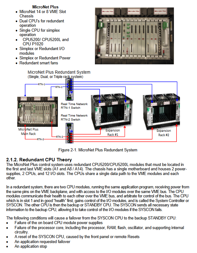
2.1 Redundant Configuration
The MicroNet Plus control system provides a complete redundancy solution, achieving high availability through dual CPU modules. In a redundant system, two CPU modules run the same application, share access to I/O modules, and communicate with each other through the VME bus. A CPU module with good health becomes the system controller (SYSCON), while another one serves as a backup (STANDBY). When the main CPU fails, the backup CPU can seamlessly take over control.
The system supports multiple redundant configuration options:
Fully redundant: Both the host rack and expansion rack use redundant CPUs and RTN modules
Partial redundancy: Main CPU redundancy, expansion rack can use single RTN or redundant RTN
Simplex configuration: Single CPU operation, expansion rack using single RTN module
2.2 Power Supply System
The MicroNet Plus chassis uses two load sharing power modules to provide redundant power supply for the motherboard, CPU, and I/O modules. The power module has a dual slot width and is located in the PS1 and PS2 slots at both ends of the chassis. The system supports three power input specifications: low voltage (24 Vdc input), high voltage (110 Vac/dc input), and high voltage 220 Vac input versions.
The power module is equipped with four LED indicator lights, which respectively display information such as power status, input faults, overheating, and power faults, making it easy to diagnose quickly. The system design follows the safety requirements of Class I and Division 2 areas and requires the use of delay fuses or circuit breakers that comply with local regulations.
2.3 I/O module and on-site connection
Each I/O module is connected to the field terminal module (FTM) through a front panel connector, which is used to connect field wiring. For the communication module, there is no need for FTM, and the cable is directly connected to the front panel of the communication module.
The system provides two levels of redundancy:
Sensor level redundancy: Connect two external input devices to two independent input channels
Module level redundancy: Connect two external input devices to two independent I/O modules
Output redundancy can be achieved by adding external relays, and for actuator output, a dual coil actuator can be used to ensure continuous operation in the event of a single point fault.
3、 Detailed Explanation of Chassis Configuration
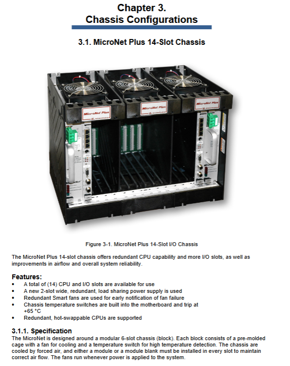
3.1 14 slot chassis
The MicroNet Plus 14 slot chassis provides redundant CPU capability and more I/O slots, while improving airflow and system reliability. The chassis adopts a modular design, with each module containing a pre formed cage, cooling fan, and high-temperature detection temperature switch. The chassis has a total of 14 CPU and I/O slots available for use.
The main features include:
New dual slot wide redundant load sharing power supply
Redundant intelligent fans can provide early notification of fan failures
The motherboard has a built-in temperature switch with a trigger point of 65 ° C ± 3 ° C
Support redundant hot swappable CPUs
3.2 8-slot chassis
The MicroNet Plus 8-slot chassis also provides redundant CPU capability and more I/O slots, adopting similar design concepts and technical features as the 14 slot chassis. The chassis has a total of 8 CPU and I/O slots available for use, and also features redundant intelligent fans and temperature monitoring functions.
4、 Analysis of CPU module technology
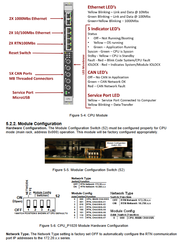
4.1 CPU P1020 module
The CPU P1020 module is based on an 800 MHz dual core processor, equipped with 512 MB RAM and 768 MB flash memory, and supports multiple communication peripherals, including 4 Ethernet ports (2 1000 Mbps, 2 100 Mbps), 2 real-time network ports, 1 service port, and 5 CAN ports.
This module supports both simplex and redundant operation modes, designed specifically for working environments in the industrial market from 0 ° C to+55 ° C. The module supports hot swapping, but it should be reset before removal to ensure elegant system failover.
4.2 PowerPC CPU 5200 module
The PowerPC CP5200 module uses the Motorola MPC5200 processor, equipped with 128 MB DDR RAM and 64 MB flash memory, and supports multiple communication peripherals, including 2 Ethernet ports, 2 real-time network ports, 1 serial port, 1 service port, and 2 CAN ports.
This module is designed for extreme industrial environments ranging from -40 to+85 ° C, with built-in FPGA providing VME bus master/slave functionality and other functions required for redundant systems.
5、 Communication module and network topology
5.1 Remote RTN module
The Remote Real Time Network (RTN) module is designed for rack expansion, with the main function of collecting local I/O module data and communicating with the host rack CPU, while providing redundant fault switching control for the rack. The RTN module supports simplex and redundant systems, and each RTN expansion chassis installs a remote RTN module in the first slot (CPU1).
5.2 SIO module
The SIO (Serial Input/Output) intelligent enhancement module provides four serial communication ports and interfaces with the VME bus. Module manages four serial ports: Port 1 and Port 2 are RS-232 ports; Ports 3 and 4 support RS-232, RS-422, or RS-485 communication protocols. The module has two LEDs (running and faulty) and no switch.
6、 Discrete I/O module
6.1 48/24 Discrete Combination Module
The HDDIO module provides 48 optically isolated discrete inputs and 24 discrete outputs, without calibration, and can be directly replaced with modules of the same model. This module supports two types of FTM I/O configurations:
Configuration 1: A 48/24 discrete FTM is connected to the HDDIO module via two high-density analog/discrete cables, and then connected to a 32 channel relay module or two 16 channel relay modules via low-density discrete cables.
Configuration 2: Two 24/12 discrete FTMs (DIN rail mounted) are connected to the HDDIO module via two high-density analog/discrete cables.
6.2 48 channel discrete input module
Each 48 channel discrete input module is connected to two independent FTMs through two low-density discrete cables. The module provides discrete signal inputs for 48 independent switch or relay contact points, which are optically isolated from other parts of the MicroNet control circuit.
6.3 64 channel discrete output module
The 64 channel discrete output module can independently control 64 outputs and operate according to commands from the CPU module. The module has no potentiometer and does not require calibration. It can be directly replaced with modules of the same model. This module can be connected to two 32 channel relay modules, four 16 channel relay modules, or a combination of both types.
7、 Analog I/O module
7.1 Intelligent Enhancement Module for Speed Sensor
This module provides four speed inputs, factory configured as MPU or Eddy inputs. The module has no potentiometer and does not require calibration. It can be directly replaced with modules of the same model. The speed input configuration depends on the module material number.
7.2 24/8 Simulated Intelligent Enhancement Module
This module provides 24 analog inputs and 8 4-20 mA outputs, without potentiometers or calibration, and can be directly replaced with modules of the same model. The module offers three different configurations, and all 4-20 mA analog inputs can be used with two-wire ungrounded (loop powered) transmitters or isolated (self powered) transmitters.
7.3 Speed/Analog IO Combination Intelligent Enhancement Module
This module provides four speed inputs (configurable as MPU, Prox, or Eddy inputs in GAP applications) as well as 12 analog inputs and 4 4-20 mA outputs. The analog input can be configured as 0-5VDC voltage mode or 4-20mA current mode in GAP applications.
8、 Safety regulations and compliance
The MicroNet digital control system follows strict safety standards and regulatory requirements:
8.1 European Compliance
CE mark: The product complies with the relevant EU directive requirements
RoHS: Compliant with Directive 2011/65/EU requirements
EMC Directive: Compliant with the 2014/30/EU Electromagnetic Compatibility Directive
Low Voltage Directive: Compliant with the 2014/35/EU Low Voltage Equipment Directive
ATEX Directive: Compliant with the 2014/34/EU Directive on Equipment for Potential Explosive Environments
8.2 North American Compliance
CSA certification: applicable to Class I, Division 2, Groups A, B, C, and D areas, with a maximum ambient temperature of 55 ° C
8.3 Classification Society Certification
American Bureau of Shipping (ABS): Complies with steel vessel code requirements
Lloyd's Register (LR): Complies with LR type approval test specifications
DNV/GL: Complies with standard certification requirements
9、 Installation and Maintenance Guide
9.1 Installation precautions
The MicroNet digital control system must be installed in a metal enclosure or cabinet to meet EMC directive requirements. Please refer to section 15 of manual 26166V2 for installation location and specific cabinet construction requirements.
The system grounding requirements are strict, and the grounding leakage current exceeds 3.5 mA. Before supplying power to the MicroNet control device, it is necessary to verify that the PE terminal is connected. Fixed wiring installation is required, and the main power circuit should be blown correctly according to national standards. It is recommended to use European T-type fuses.
9.2 Electrostatic discharge protection
The electronic control device contains electrostatic sensitive components, and the following precautions should be taken to prevent damage:
Release body static electricity before handling control devices
Avoid using plastic, vinyl and foam around printed circuit boards
Do not touch the components or conductors on the printed circuit board with your hands or conductive devices
9.3 Fault diagnosis and troubleshooting
The system provides comprehensive diagnostic functions, which can monitor system status, view fault codes, and configure network settings through AppManager software. Each module is equipped with LED indicator lights to display module status and fault information, making it easy to quickly locate and solve problems.
10、 Technological development trends and application prospects
With the advancement of Industry 4.0 and digital transformation, MicroNet digital control systems continue to evolve and integrate new technologies to meet more stringent industrial application requirements
10.1 Intelligent Upgrade
The new generation MicroNet control system has strengthened support for condition monitoring and predictive maintenance, helping users optimize equipment performance and reduce unexpected downtime by integrating more advanced diagnostic algorithms and data analysis functions.
10.2 Communication Protocol Extension
The system continues to expand its support for modern industrial communication protocols, including OPC UA, MQTT, and higher-level Ethernet protocols, ensuring seamless integration with factory information systems.
10.3 Network Security Enhancement
Faced with increasingly severe industrial network security challenges, Woodward continuously strengthens the security features of MicroNet control systems, including secure boot, communication encryption, and access control functions.
- OMRON
- ABB
- General Electric
- EMERSON
- Honeywell
- HIMA
- ALSTOM
- Rolls-Royce
- MOTOROLA
- Rockwell
- Siemens
- Woodward
- YOKOGAWA
- FOXBORO
- KOLLMORGEN
- MOOG
- KB
- YAMAHA
- BENDER
- TEKTRONIX
- Westinghouse
- AMAT
- AB
- XYCOM
- Yaskawa
- B&R
- Schneider
- KONGSBERG
- NI
- WATLOW
- ProSoft
- SEW
- ADVANCED
- Reliance
- TRICONEX
- METSO
- MAN
- Advantest
- STUDER
- DANAHER MOTION
- Bently
- Galil
- EATON
- MOLEX
- DEIF
- B&W
- ZYGO
- Aerotech
- DANFOSS
- Beijer
- Moxa
- Rexroth
- Johnson
- WAGO
- TOSHIBA
- BMCM
- SMC
- HITACHI
- HIRSCHMANN
- Application field
- XP POWER
- CTI
- TRICON
- STOBER
- Thinklogical
- Horner Automation
- Meggitt
- Fanuc
- Baldor
- SHINKAWA
- Other Brands
- UniOP
- KUKA
- Iba
- Beckhoff
- ADLINK
-
 Basler Electric BE1-700 Digital Protective Relay
 -
 Basler Electric SR8A-2B01B3A Static Voltage Regulator
 -
 Basler Electric SR4A-2B01B3E Static Voltage Regulator
 -
 Basler Electric 9017709102 PC Board
 -
Basler Electric SR4A-2B01B3A Static Voltage Regulator
-
 Basler Electric PRS-250 Veri-Sync Relay
 -
 Basler Electric 9066800102 Excitation Support System
 -
 Basler Electric BE1-87G Generator Differential Relay 9 1708 18 100
 -
 Basler Electric 36T865-2 BE03752001 Power Supply
 -
 Basler Electric M-300 149D940G02 Power Supply
 -
 Basler Electric ACA2040-25GM 4Mp 25Fps Area Scan Camera
 -
 Basler BE1-87G-S1A-A1C-A0N0 Differential Relay
 -
 Basler SR8A-2B06B3E Static Regulator SR8A2B06B3E
 -
 Basler SCP-210 Frequency Controller 9095400100
 -
 Basler BE1-59-A3E-A1J-N1N3F Overvoltage Relay BE159A3EA1JN1N3F
 -
 Basler 9 2011 11 100 Bracket Mounted Terminal Unit
 -
Basler 9 1606 00 101 Voltage Regulator
-
 Basler CBS-377 Current Boost System 9109600102
 -
 Basler 8650C72 Exciter Control Module PCB Rev 5
 -
 Basler C2EE1PA0N1F BE1-32R Reverse Power Relay
 -
 ADLINK HPCI-14S12U - Industrial Control Backplane 12PCI Backplane PCI-14S Passive Backplane
 -
-0010.png) ADLINK PCIe-GIE74C - image acquisition card 4-CH GigE Vision PoE+ Frame Grabber
ADLINK PCIe-GIE74C - image acquisition card 4-CH GigE Vision PoE+ Frame Grabber -
-0010_1.png) ADLINK PCI-8164 - control card 4-Axis Advanced Motion Controller Board
ADLINK PCI-8164 - control card 4-Axis Advanced Motion Controller Board -
 ADLINK PCIe-U304 - 4 Port USB3 PCIe Frame Grabbers USB Screw Hole Card
 -
 ADLINK PCI-9112 - Multi-Function Data Acquisition Card DAQ Card
 -
 ADLINK PCI-7432 - 51-12013-0A50 4-CH Isolated Numérique I/O PCI Cartes Digital I/O Card
 -
 ADLINK PCA-6106P3-0C1 REV.C1 - backplane 6-Slot Passive Backplane Board
 -
 ADLINK PCI-7224 - 24-CH Opto-Isolated Digital I/O PCI Board
 -
 ADLINK CPCI-7433R(G) - Digital Input Board Rear I/O CompactPCI Card
 -
 ADLINK EBP-13E4 - 51-46703-0A30 Industrial PC Backplane Passive Backplane
 -
 ADLINK PCIE-HDV62 - Image acquisition card High Definition Video Frame Grabber
 -
 ADLINK EBP-13E4 - 51-46703-0A30 Industrial Backplane Board Passive Backplane
 -
 ADLINK 90111-B1 / CPCI-6770 - PCB CPU MODULE CompactPCI Single Board Computer
 -
 ADLINK PCI-7248 - DATA ACQUISITION PCI CARD 48-CH Parallel Digital I/O Board
 -
 ADLINK PCI-7230 - 51-12003-0a50 board PCI7230 32-CH Isolated Digital I/O Card
 -
 ADLINK PCI2A000CB - 51-20000-0B30 Multi-Function DAQ Card Baseboard
 -
 ADLINK PCI-8134-005 - 4-Axis Motion Controller Card
 -
 ADLINK PCI-7224 - 24-CH Opto-Isolated Digital I/O PCI Card
 -
 ADLINK PCI-7434 - 64-CH Isolated Digital Output Card
 -
 ADLINK PCI-8132 - motion control card 2-Axis Servo & Stepper Controller
 -
 ADLINK PCI-8134 - Motion Controller PCI Card 4-Axis Controller Board
 -
 ADLINK PCI-8164 - Motion Control Card 51-12406-0A40 4-Axis Controller
 -
 ADLINK 51-12001-0C20 - Circuit Board Data Acquisition Interface Module Hardware
 -
 ADLINK NuPR0-840 - industrial control motherboard Full-Size PICMG CPU Board
 -
 ADLINK PCI-7444 - 51-12023-0A10 card 128-CH Isolated Digital Output Board
 -
 ADLINK PCI-1612B - data acquisition card 4-Port RS-232/422/485 Serial Communication Card
 -
 ADLINK PCI-6208V 009 - 8/16-CH 16-Bit Analog Output Cards PCB-I-E-482=6BX3
 -
 ADLINK NUPRO-935A/LV - industrial control motherboard Full-Size PICMG SBC Board
 -
 ADLINK PCI-9114DG - Multi-Function DAQ Card Data Acquisition PCI Card
 -
 ADLINK ACL-7130 - Data acquisition card Isolated Digital I/O Board
 -
 ADLINK ABX-6300D-4E1-BP - board ABX6300D4E1BP Video Interface Expansion Card
 -
 ADLINK CPCI-6940 - CPCI-6940/D1539/M16-0(EA)-000E 6U CompactPCI Processor Board
 -
 ADLINK NuPRO-760 - industrial control motherboard Half-Size PICMG SBC CPU Board
 -
 ADLINK IMB-M42H (G)-0020 - industrial control motherboard LGA1155 Micro-ATX Mainboard
 -
 ADLINK RTV-24 / PCI-MP4S - 51-12519-1C30 4-Channel Real Time Video Capture Board
 -
 ADLINK PCI-8134 - 4-Axis Servo & Stepper Motion Controller Card
 -
 ADLINK MXC-6101D - V.PC000.002.ST.00 Box PC Configurable Embedded Computer
 -
.png) ADLINK PCI-8134A - 51-12421-0A10 Motion Control Card 4-Axis Controller Card
ADLINK PCI-8134A - 51-12421-0A10 Motion Control Card 4-Axis Controller Card -
 ADLINK DIN-100S / DIN-100SA1 - Technology SCSI-II TB 100-PIN Terminal Block Board
 -
.png) ADLINK DIN-812M001 / DIN812M001 - 51-14034-0A1 51140340A1 Terminal Module Breakout Interface
ADLINK DIN-812M001 / DIN812M001 - 51-14034-0A1 51140340A1 Terminal Module Breakout Interface -
_1.png) ADLINK PCI-8164 - Servo motion control 4-Axis Advanced Controller Card
ADLINK PCI-8164 - Servo motion control 4-Axis Advanced Controller Card -
 ADLINK PCIe-GIE64 - Acquisition card GigE Vision PoE+ Frame Grabber
 -
 ADLINK M-302 - Industrial control motherboard ATX PC Board Mainboard
 -
 ADLINK PCI-8134 - Motion Controller PCI Card 4-Axis Controller Board
 -
 ADLINK PCI-RTV24 - Image capture card Analog Video Frame Grabber
 -
 ADLINK PCI-8102 - Motion control card 2-Axis Servo & Stepper Controller Board
 -
 ADLINK PCI-9112 REV.B1 - Card Multi-Function Data Acquisition Card
 -
 ADLINK HSI-DI32-M-N / HSL-TB32-M-DIN - Discrete I/O MODULE Distributed Automation Module System
 -
 ADLINK PCI-7296 - IO card REV.A3 96-CH Parallel Digital I/O Card
 -
-0020.png) ADLINK DIN-814P-A4 / 814Y - terminal board Motion Control Interface Block
ADLINK DIN-814P-A4 / 814Y - terminal board Motion Control Interface Block -
 ADLINK DIN-814P-A4 - 51-14056-0A10 PCB-I-E-2736=ZA01 Screw Terminal Board Breakout
 -
 ADLINK M-322 - motherboard Industrial Control Computer Mainboard
 -
 ADLINK NUPRO-406 REV:B1 - industrial control motherboard Full-Size PICMG CPU Board
 -
 ADLINK AMP-204C - card DSP-Based 4-Axis Advanced Pulse-Train Controller
 -
 ADLINK HPCI14S REV.B1 - industrial computer baseboard 14-Slot Passive Backplane
 -
 ADLINK PCI-7250 - 8-CH Relay Output & 8-CH Isolated DI PCI Card
 -
 ADLINK EBP-13E2 - baseplate Passive Backplane Industrial Computer Chassis Board
 -
 ADLINK LPCI-3488A - PCI-GPIB card 51-12801-0A30 acquisition card IEEE-488 Interface Board
 -
 ADLINK PCI-6216V-GL - 51-12201-0C30 16-CH 16-Bit Voltage Analog Output Card
 -
 ADLINK ACL-8454 - 16-CH Isolated Digital I/O & 4-CH Counter Card
 -
 ADLINK HPCI-9S7U - backplane Passive Backplane Compatible with NuPRO-A301 852 841 842
 -
 ADLINK DAQ-2010-007 - Simultaneous-Sampling Multi-Function Data Acquisition Card
 -
 ADLINK MP-C154 - 51-64205-0A10 Motion Control Card 4-Axis Controller Board
 -
 ADLINK MXE-202/mSSD16B/WiFi-BT - Matrix Rugged I/O Platform Embedded Fanless Computer
 -
 ADLINK CM-920-R-17 - PC/104-Plus Single Board Computer Module Intel Celeron M
 -
 ADLINK PCI-7250 NSMP - 8-CH Relay Output & 8-CH Isolated DI Card
 -
 ADLINK PCI-8164 - 4-Axis Motion Controller PCI Card W/ Cable and Breakout Box
 -
 ADLINK EMX-100 - Ethernet-based 4-axis Motion Controllers Distributed Motion Module
 -
.png) ADLINK PCI-8134A - Press control card 4-Axis Motion Controller Board
ADLINK PCI-8134A - Press control card 4-Axis Motion Controller Board -
 ADLINK M-845EG REV:3.2 - industrial motherboard Pentium 4 Socket 478 Micro-ATX
 -
 ADLINK PCI-9114A Rev A2 DG - card High-Resolution Multi-Function Data Acquisition Board
 -
 ADLINK IEC-915GV - REV 1.1 Industrial motherboard Socket 478 CPU Board
 -
 ADLINK PCI-9111DG(G) - Data Acquisition Card Multi-Function DAQ Card
 -
 ADLINK HPCI-15S10 REV:B2 - Industrial computer base plate Passive Backplane Board
 -
 ADLINK NuPR0-840 / NuPR0-840DV - industrial control motherboard Full-size PICMG CPU Board
 -
 ADLINK RTV-24 / PCI-MP4S - 51-12519-1C30 4-Channel Real Time Video Capture Board
 -
 ADLINK NUPRO-780 - industrial control motherboard Pentium III Single Board Computer
 -
 ADLINK PCI-7296 - 0050 card 96-CH Opto-Isolated Parallel DIO Card Set
 -
-0040.png) ADLINK NUPRO-780 - industrial control motherboard PICMG Full-Size SBC
ADLINK NUPRO-780 - industrial control motherboard PICMG Full-Size SBC -
 ADLINK PCI-7248 - 51-12006-0A3 002 Pci 7248 48-CH Parallel Digital I/O Card
 -
 ADLINK PCI-7230 - 32-CH Isolated Digital I/O Card
 -
 ADLINK AMP-204C - motion control card 4-Axis Advanced Controller Board
 -
.png) ADLINK PCI-1714UL - Card Ultra High-Speed 4-CH Simultaneous Sampling DAQ
ADLINK PCI-1714UL - Card Ultra High-Speed 4-CH Simultaneous Sampling DAQ -
 ADLINK NuPRO-E330 - industrial computer equipment motherboard PICMG 1.3 SHB SBC
 -
 ADLINK AMP-204C - DSP-Based 4-Axis Advanced Pulse-Train Motion Controller Module
 -
 ADLINK PCI-7256 - 001 51-12206-0A2 REV.A2 LPCI-7256 16-CH Latching Relay Output Card
 -
 ADLINK ND6050 - NUDAM DIGITAL I/0 MODULE Distributed I/O Unit
 -
 ASEM BM100 - Box PC Embedded Fanless Industrial Computer
 -
-3650.png) ADLINK PCI-7250 - PCI Acquisition Card 8-CH Relay Output & Isolated DI Board
ADLINK PCI-7250 - PCI Acquisition Card 8-CH Relay Output & Isolated DI Board -
 ADLINK PCI-8164 - Servo motion control 4-Axis Controller Card
 -
 ADLINK NuPRO-A40H - Industrial Motherboard 51-41807-1A30 OSP LGA1155 H61
 -
 ADLINK ADMAX X300 SERVER - 51066010-0A30 motherboard Multi-Processor Mainboard
 -
 ADLINK CMe-GIE62+ - 51-32903-0A30 control card PC/104-Plus GigE Vision Frame Grabber
 -
 ADLINK NUPRO-780 - industrial control motherboard Full-Size PICMG SBC CPU Board
 -
 ADLINK ETX-AT-N270-18/GKTEL - 51-71111-OB10 motherboard ETX CPU Module Board
 -
 ADLINK DIN-812M - interface module Terminal Block Connection Board
 -
 ADLINK IMB-M42H - industrial control motherboard LGA1155 Micro-ATX Mainboard
 -
ADLINK PXIS-2508 - 8-slot 3U PXI Instrument Chassis Power Hardware Assembly
-
ADLINK AMP-208C - Motion Control card DSP-Based 8-Axis Pulse-Train Controller
-
ADLINK PCI-9111 / PCI-9111DG - Multi-Function Data Acquisition Card DAQ Board
-
ADLINK IEEE-488 GPIB card - Bus Interface Controller Communication Board
-
ADLINK RTV-24 - 51-12519-1C30 image acquisition card Video Frame Grabber Card
-
ADLINK TB-24P/24-01 - Board 24 Way Screw Terminal Breakout Board
-
ADLINK HSL-DI16DO16-DB-NN - 51-23015-0A40 Distributed Discrete I/O Module Set
-
ADLINK PCI-7442 - switch quantity card data acquisition card 64-CH Isolated Card
-
ADLINK ACL-7130 REV. B2 - industrial control capture card Isolated Digital I/O PCI Card
-
ADLINK PCI-6S / PCI6S - Backplane 6-Slot Passive Backplane Chassis Board
-
ADLINK ACL-8113A - card Isolated Digital Input Card


