
Woodward MicroNet TMR 5009 Digital Control System: Authoritative Guide to Hardware Installation and Configuration
Woodward MicroNet TMR 5009 Digital Control System: Authoritative Guide to Hardware Installation and Configuration
Introduction: Redundant Core of Industrial Control
In the control field of key prime movers such as gas turbines and steam turbines, the reliability, safety, and fault tolerance of the system are of utmost importance. The MicroNet TMR 5009 digital control system launched by Woodward has become a benchmark in the field of high availability industrial control with its triple modular redundancy (TMR) architecture. This manual (85580V2, revised E) serves as the second volume of the four volume set of technical documents, providing a detailed explanation of the hardware composition, mechanical and electrical installation, troubleshooting, and maintenance specifications of the 5009 control system. This article aims to provide a comprehensive installation, debugging, and maintenance guide for engineering and technical personnel by delving into the core content of the manual, ensuring that the control system can operate safely, stably, and efficiently.
Chapter 1: System Overview and Security Principles
1.1 System documentation and scope of application
The technical documentation for MicroNet TMR 5009 is divided into four volumes, with this volume (Installation/Hardware Manual) focusing on hardware level information. It covers basic maintenance processes such as hardware description, mechanical and electrical installation steps, hardware specifications, troubleshooting guides, and module replacement. The manual is applicable to a series of 5009 part numbers (such as 9907-794 to 9907-1012, etc.) and provides general guidance, but users must apply it in conjunction with the specific system configuration (such as whether it includes cabinets, operator interfaces, etc.).
1.2 Critical Safety Warning
The manual emphasizes the importance of safety at the beginning, and all installation, operation, or maintenance personnel must read the entire text and related publications before starting work.
Overspeed protection: The prime mover must be equipped with an overspeed shutdown device that is completely independent of the control system to prevent speeding accidents and ensure personal and equipment safety.
Personal protective equipment (PPE): When operating, it is necessary to wear appropriate PPE according to the job content, such as goggles, hearing protection devices, safety helmets, gloves, safety boots, and respirators.
Emergency preparedness: When starting the prime mover, it is necessary to be prepared for emergency shutdown.
Electrostatic Discharge (ESD) Protection: The control module contains components that are sensitive to static electricity. Strict procedures must be followed during handling: contact the grounding surface to release body static electricity in the event of a power outage; Avoid using materials such as plastic and vinyl around the circuit board that are prone to static electricity; Do not touch the components or conductors on the printed circuit board with your hands or conductive devices. Suggest referring to Woodward manual 82715.
Hazardous Area Compliance: Unless otherwise specified, this equipment is suitable for Class I, Division 2, Groups A, B, C, D hazardous or non hazardous areas. Key limitation: If an F/T relay module (DTM) is installed, the entire device is no longer suitable for Class I, Division 2 hazardous areas and can only be used in ordinary (non hazardous) locations. All wiring must comply with the corresponding hazardous area wiring specifications.
High voltage warning: If there is a 125 Vdc voltage on the DTM terminal block, then there is also high voltage on the discrete module cable. Extreme care must be taken to avoid contact with cables when power cannot be cut off.
Chapter 2: In depth Analysis of Hardware Architecture
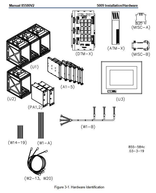
The 5009 system can provide various hardware configurations according to requirements, with the main components as follows:
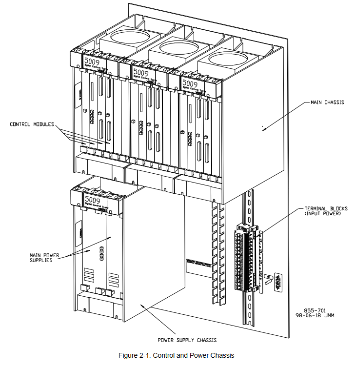
2.1 Main control chassis and power architecture
Main control chassis (U1): adopts VME (VERSAmodule Eurocard) bus structure, including three independent six slot core parts (A, B, C). Each kernel is physically and electrically isolated from each other to ensure that a single kernel failure does not cause system shutdown. The chassis is cooled by forced air cooling, and each six slot card holder is equipped with a cooling fan.
Power system:
Power case (U2): accommodates two pluggable main power modules (PA1, PA2), providing input power conversion.
Main power module: Various models (LVDC: 18-32 Vdc; AC/DC: 88-132 Vac/100-150 Vdc; HVAC/DC: 180-264 Vac/200-300 Vdc), can be paired and mixed to form a redundant power supply system. They generate six independent 24 Vdc outputs, which are shared by the load to power three cores.
Core power module (A1): One for each core, converting 24 Vdc to a stable 5 Vdc and 5 V pre charging power supply for use by other modules within the core, and allowing hot swapping of I/O modules.
2.2 Core functional modules
The standard configuration for each kernel includes:
Central processing unit module (CPU, A2): using Motorola 68040 microprocessor to execute control logic and operations. The front panel includes an RS-232 serial port, PCMCIA slot for downloading applications, real-time clock battery, and status indicator lights (running, low voltage, I/O lock, fault).
MPU and Analog I/O Module (A3): Integrated with driver circuits for 4 speed sensor inputs, 8 analog inputs (4-20 mA), 4 analog outputs (4-20 mA), and 2 proportional actuator outputs. All calibrations are completed through software without potentiometers.
Discrete I/O module (A4): processes 24 discrete inputs (dry contacts) and 12 relay output commands. Input isolation is achieved through optocouplers.
Serial Input/Output Module (SIO, A5): Optional module, usually installed in the A and B cores. Provide additional serial communication ports (RS-232/422/485) to enhance communication redundancy and capability.
2.3 Terminal Module: On site Interface
Analog Terminal Modules (ATM-1, ATM-2): Installed on standard DIN rails. As the interface between on-site analog signals (speed, analog I/O, actuator) and analog I/O modules within three cores. Provide signal routing, summation, and isolation power supply (for proximity switch probes) functions.
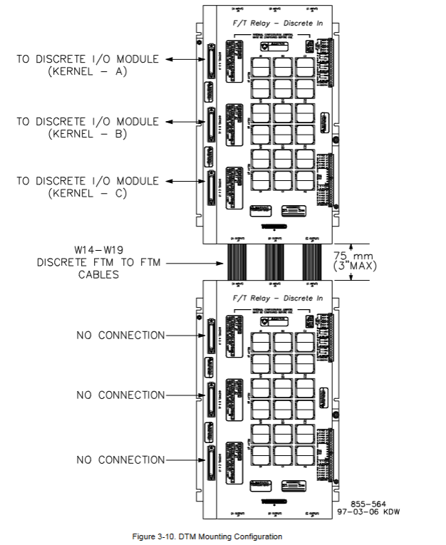
Discrete terminal module (DTM-1 to DTM-4): used to connect on-site discrete wiring (contact input and relay output). Each DTM processes 6 contact inputs and 3 relay outputs. The relay output adopts a unique 6-relay fault-tolerant configuration, supporting latent fault detection (LFD), which can detect relay faults without affecting the output status.
2.4 Optional Components
Cabinet: Standard floor standing front door cabinet (compliant with NEMA 12/IP55), weighing approximately 272 kilograms. The control system can be installed as a whole inside the factory, providing integrated power interface board and wiring management.
OpView ™ Operator Interface (U3): A computer-based touchscreen workstation used as a touchscreen alarm and remote control panel.
Chapter 3: Detailed explanation of mechanical installation steps
3.1 Preparation before installation
Storage: The device should be stored in an environment with a temperature of -20 ° C to+70 ° C and a humidity of ≤ 90% (non condensing). When stored for a long time, the main power supply needs to be powered on at least once every 18 months.
Open box inspection: Carefully inspect all components (see Table 3-1) for damage. Systems with cabinets are shipped as a complete package, while those without cabinets are shipped as individual parts.
3.2 Installation process
Site selection: Choose a location that is dry, well ventilated, with an ambient temperature of 0-55 ° C (0-46 ° C inside the cabinet), and away from strong electromagnetic interference. Ensure good grounding.
Installation of cabinet (if equipped): Fix with standard floor brackets, introduce cables from the bottom, and reliably ground with ≥ 10 mm ² wires.
Installation of chassis: Install the main control chassis and power chassis on the panel or backplane at a specified distance (50-200 mm). Connect the two using the provided W1-B cable and ensure that the chassis is grounded.
Installation module: In the event of a power outage, insert each module (power supply, CPU, I/O, etc.) accurately into the corresponding slot of the main control chassis according to the slot identification (Figure 3-6), and tighten it with screws. Do not use brute force.
Install terminal module:
ATM: Installed on a well grounded DIN rail, and reliably grounded its "chassis ground" terminal using the accompanying grounding terminal (Misc A) and short wire (≤ 15 cm).
DTM: Master DTM (1,3) must be installed directly above Slave DTM (2,4). Ensure that the installation panel is reliably grounded.
Install OpView: Install according to the template (Figure 3-12) to ensure sufficient heat dissipation space is reserved.
Chapter 4: Electrical Installation and Wiring Specifications
4.1 General Principles
All on-site wiring must meet a temperature rating of at least 75 ° C.
Following EMC standards, analog and discrete I/O wiring must be separated from power lines.
Use shielded twisted pair cables to connect speed sensors, analog I/O, and communication ports. The shielding layer should be grounded at a single point at the control terminal and all intermediate terminal blocks, with an exposed wire length not exceeding 25 mm.
4.2 Power Wiring
Each main power supply must be equipped with an independent branch circuit protection (fuse or circuit breaker), with a rated value not exceeding 250% of the rated input current of the power supply (see Table 4-1). Slow melting protective devices must be used.
The input power wire diameter must meet the requirements in Table 4-1 (e.g. 10 mm ² or 8 AWG wire is required for a 24 Vdc power supply).
The three isolated 24 Vdc outputs (A, B, C) of the system must remain isolated and must not be short circuited externally, otherwise a short circuit at one point may cause the entire control system to lose power.
The leakage current exceeds 3.5 mA, therefore a protective earth (PE) connection is mandatory.
4.3 Detailed explanation of signal wiring
Speed sensor input: Supports passive magneto electric speed sensors (MPU) or active proximity switch probes (12/24 Vdc). MPU needs to install jumpers to enable three core detection; The proximity probe is provided with isolated power supply by ATM. Attention should be paid to frequency and voltage range limitations.
Analog input (4-20 mA): Supports two-wire (loop power supply) or four wire (self powered) transmitters. Attention should be paid to whether a common terminal jumper needs to be installed when wiring. The input impedance is 200 Ω.
Analog output (4-20 mA): The maximum driving capacity is 600 Ω load. Output non isolated, attention should be paid to the grounding loop.
Output of actuator: It can be configured to drive single coil or double coil actuators, with an output range of 4-20 mA or 20-160 mA. When wiring, specified jumpers need to be installed or removed according to the configuration.
Discrete (contact) input: 24 inputs, of which 4 have fixed functions (external emergency stop, reset, speed up, speed down). The contact wetting voltage can be provided by internal 24 Vdc, external 18-32 Vdc, or 100-150 Vdc (UL only). When using the internal power supply, jumper wires need to be installed on the DTM.
Relay output: 12 outputs, of which 2 have fixed functions (shutdown relay, alarm relay). Each route consists of 6 relays in series and parallel to achieve fault tolerance and latent fault detection.
LFD configuration: LFD is only suitable for circuits with 18-32 Vdc, 88-132 Vac, or 100-150 Vdc. It will inject a small leakage current into the load to detect faults when the relay is disconnected. It is necessary to verify whether the leakage voltage on the load is lower than its release voltage through the curves in Figures 4-10 to 4-12, otherwise LFD or parallel shunt resistor should be disabled.
Jumper setting: Each relay output requires two sets of jumpers: one set selects the circuit voltage to match the LFD logic, and the other set selects whether to detect normally open (NO) or normally closed (NC) contacts. It is recommended to use internal 24 Vdc for the relay coil power supply.
4.4 Communication and System Power on
Serial communication: The system provides multiple RS-232/422/485 ports for connecting engineering workstations (PCI), Modbus devices, printers (connected to CPU-B or SIO Port 1), OpView, etc. The communication distance of RS-232 is limited to 15 meters, and longer distances require the use of RS-422/485 or a converter.
System power on:
Turn on both main power sources in sequence and confirm that only the green "OK" LED is lit.
Instantly turn the "Reset/Run" switch of the A, B, and C core CPUs to the reset position and then turn it back.
The system will perform offline diagnosis (taking several minutes). After completion, all CPU red fault lights should turn off, green running lights should turn on, and the application program will start running.
Warning: Before starting the turbine for the first time, it is necessary to verify the calibration of all external input and output devices.
Chapter 5: Troubleshooting and Module Replacement
This chapter provides detailed LED status instructions, diagnostic procedures, and module replacement steps.
5.1 Key points for module diagnosis and replacement
Main power module: The status is indicated by the front panel LED (normal, input fault, overheating, power fault). When replacing, the input power must be disconnected first.
Kernel power module: Before replacement, it is necessary to use an engineering workstation to confirm that other kernels are running normally, then reset the CPU of that kernel, and first unplug all other modules in that kernel before replacing the kernel power supply.
CPU module: indicates status through running, I/O lockout, low VCC, and watchdog LED. Before replacing, confirm that other CPUs are functioning properly, reset the target CPU, disconnect the communication cable, and then replace.
I/O module (analog/discrete): The fault LED is constantly on or flashing, indicating a module fault. Key steps for hot plugging: First, release the module to disconnect it from the motherboard but still plug it into the slot, then disconnect the I/O cable and remove the faulty module; When installing a new module, first insert the module (without forcefully pressing it to the bottom), connect the I/O cable, and finally fully press the module into the motherboard socket and tighten it. This sequence can avoid system tripping caused by pin short circuits.
Terminal module (ATM/DTM): It is recommended to replace it when the system is offline. The fuse (24 Vdc/0.1 A) on the ATM can be replaced online. When replacing DTM relays, be sure to pay attention to high voltage hazards.
5.2 System Diagnosis
Offline diagnosis: Execute after CPU reset to detect core hardware such as memory, communication, clock, etc. The fault is represented by the flashing frequency code of the CPU fault LED (Table 5-1).
Online diagnosis: continuous during runtime, detecting task timeouts, memory errors, etc. The fault information is displayed in the OpSys fault mode of the engineering workstation (Table 5-2).
5.3 Comprehensive Investigation Guidelines
The manual provides a comprehensive system troubleshooting checklist (pages 79-80), covering various aspects such as actuators, linkage mechanisms, valves, oil circuits, steam conditions, input/output signals, sensors, power supplies, wiring, external devices, etc. It is a valuable tool for systematic fault location.
Chapter 6: Quick Check of Hardware Specifications
This chapter provides technical parameters for all key components, which serve as the basis for selection and acceptance.
Compliance and Certification: Compliant with EMC (EN 61000-6-2, -6-4) and Low Voltage Directive (EN50178). Certified by UL/cUL, suitable for Class I Div. 2 (excluding F/T relay modules) or ordinary locations. Lloyd's ENV1/ENV2 certification.
Environment: Working temperature 0-55 ° C; Storage temperature -20-70 ° C; Pollution level 2.
Power specifications: Detailed list of rated current, power, protector specifications, wire diameter, and holding time for various input voltage ranges.
I/O specifications:
Speed input: MPU (100-25k Hz, 1-25 Vrms); Proximity probe (0.5-25k Hz).
Analog input: 8 channels, 4-20 mA, 16 bit precision, 200 Ω impedance.
Analog output: 4 channels, 4-20 mA, maximum 600 Ω load.
Executive output: 2 channels, configurable for 4-20 mA (360 Ω) or 20-160 mA (45 Ω).
Discrete input: 24 channels, optocoupler isolation.
Relay output: 12 channels, contact capacity detailed in the manual (such as 28 Vdc/10A, 120Vac/15A, etc.).
Cabinet: Size approximately 2251H x 599W x 834D mm, weight approximately 272 kg, NEMA 12/IP55 protection.
Chapter 7: Preventive Maintenance
Regular inspection: Cable connection status.
Fan replacement: It is recommended to replace the cooling fans of the main chassis and power supply chassis every 50000 operating hours; The cabinet door fan is replaced every 60000 hours.
Air filter: Regularly clean the intake filter of the cabinet fan.
Battery inspection: Regularly check the CPU battery for any signs of leakage, swelling, or damage.
Chapter 8: Introduction to Compatible Products
Briefly introduced Woodward products that can be used with the 5009 system, including:
Operator Control Panel (OCP): A hardware panel that provides local start stop, speed regulation, and other functions.
Digital Synchronization and Load Control (DSLC): Used for synchronization, load distribution, VAR/PF control, etc. in generator applications.
Real power sensor (RPS): measures the generator or active power and provides a 4-20 mA signal to the 5009 system.
- OMRON
- ABB
- General Electric
- EMERSON
- Honeywell
- HIMA
- ALSTOM
- Rolls-Royce
- MOTOROLA
- Rockwell
- Siemens
- Woodward
- YOKOGAWA
- FOXBORO
- KOLLMORGEN
- MOOG
- KB
- YAMAHA
- BENDER
- TEKTRONIX
- Westinghouse
- AMAT
- AB
- XYCOM
- Yaskawa
- B&R
- Schneider
- KONGSBERG
- NI
- WATLOW
- ProSoft
- SEW
- ADVANCED
- Reliance
- TRICONEX
- METSO
- MAN
- Advantest
- STUDER
- DANAHER MOTION
- Bently
- Galil
- EATON
- MOLEX
- DEIF
- B&W
- ZYGO
- Aerotech
- DANFOSS
- Beijer
- Moxa
- Rexroth
- Johnson
- WAGO
- TOSHIBA
- BMCM
- SMC
- HITACHI
- HIRSCHMANN
- Application field
- XP POWER
- CTI
- TRICON
- STOBER
- Thinklogical
- Horner Automation
- Meggitt
- Fanuc
- Baldor
- SHINKAWA
- Other Brands
- UniOP
- KUKA
- Iba
- Beckhoff
- ADLINK
-
 Basler Electric BE1-700 Digital Protective Relay
 -
 Basler Electric SR8A-2B01B3A Static Voltage Regulator
 -
 Basler Electric SR4A-2B01B3E Static Voltage Regulator
 -
 Basler Electric 9017709102 PC Board
 -
Basler Electric SR4A-2B01B3A Static Voltage Regulator
-
 Basler Electric PRS-250 Veri-Sync Relay
 -
 Basler Electric 9066800102 Excitation Support System
 -
 Basler Electric BE1-87G Generator Differential Relay 9 1708 18 100
 -
 Basler Electric 36T865-2 BE03752001 Power Supply
 -
 Basler Electric M-300 149D940G02 Power Supply
 -
 Basler Electric ACA2040-25GM 4Mp 25Fps Area Scan Camera
 -
 Basler BE1-87G-S1A-A1C-A0N0 Differential Relay
 -
 Basler SR8A-2B06B3E Static Regulator SR8A2B06B3E
 -
 Basler SCP-210 Frequency Controller 9095400100
 -
 Basler BE1-59-A3E-A1J-N1N3F Overvoltage Relay BE159A3EA1JN1N3F
 -
 Basler 9 2011 11 100 Bracket Mounted Terminal Unit
 -
Basler 9 1606 00 101 Voltage Regulator
-
 Basler CBS-377 Current Boost System 9109600102
 -
 Basler 8650C72 Exciter Control Module PCB Rev 5
 -
 Basler C2EE1PA0N1F BE1-32R Reverse Power Relay
 -
 ADLINK HPCI-14S12U - Industrial Control Backplane 12PCI Backplane PCI-14S Passive Backplane
 -
-0010.png) ADLINK PCIe-GIE74C - image acquisition card 4-CH GigE Vision PoE+ Frame Grabber
ADLINK PCIe-GIE74C - image acquisition card 4-CH GigE Vision PoE+ Frame Grabber -
-0010_1.png) ADLINK PCI-8164 - control card 4-Axis Advanced Motion Controller Board
ADLINK PCI-8164 - control card 4-Axis Advanced Motion Controller Board -
 ADLINK PCIe-U304 - 4 Port USB3 PCIe Frame Grabbers USB Screw Hole Card
 -
 ADLINK PCI-9112 - Multi-Function Data Acquisition Card DAQ Card
 -
 ADLINK PCI-7432 - 51-12013-0A50 4-CH Isolated Numérique I/O PCI Cartes Digital I/O Card
 -
 ADLINK PCA-6106P3-0C1 REV.C1 - backplane 6-Slot Passive Backplane Board
 -
 ADLINK PCI-7224 - 24-CH Opto-Isolated Digital I/O PCI Board
 -
 ADLINK CPCI-7433R(G) - Digital Input Board Rear I/O CompactPCI Card
 -
 ADLINK EBP-13E4 - 51-46703-0A30 Industrial PC Backplane Passive Backplane
 -
 ADLINK PCIE-HDV62 - Image acquisition card High Definition Video Frame Grabber
 -
 ADLINK EBP-13E4 - 51-46703-0A30 Industrial Backplane Board Passive Backplane
 -
 ADLINK 90111-B1 / CPCI-6770 - PCB CPU MODULE CompactPCI Single Board Computer
 -
 ADLINK PCI-7248 - DATA ACQUISITION PCI CARD 48-CH Parallel Digital I/O Board
 -
 ADLINK PCI-7230 - 51-12003-0a50 board PCI7230 32-CH Isolated Digital I/O Card
 -
 ADLINK PCI2A000CB - 51-20000-0B30 Multi-Function DAQ Card Baseboard
 -
 ADLINK PCI-8134-005 - 4-Axis Motion Controller Card
 -
 ADLINK PCI-7224 - 24-CH Opto-Isolated Digital I/O PCI Card
 -
 ADLINK PCI-7434 - 64-CH Isolated Digital Output Card
 -
 ADLINK PCI-8132 - motion control card 2-Axis Servo & Stepper Controller
 -
 ADLINK PCI-8134 - Motion Controller PCI Card 4-Axis Controller Board
 -
 ADLINK PCI-8164 - Motion Control Card 51-12406-0A40 4-Axis Controller
 -
 ADLINK 51-12001-0C20 - Circuit Board Data Acquisition Interface Module Hardware
 -
 ADLINK NuPR0-840 - industrial control motherboard Full-Size PICMG CPU Board
 -
 ADLINK PCI-7444 - 51-12023-0A10 card 128-CH Isolated Digital Output Board
 -
 ADLINK PCI-1612B - data acquisition card 4-Port RS-232/422/485 Serial Communication Card
 -
 ADLINK PCI-6208V 009 - 8/16-CH 16-Bit Analog Output Cards PCB-I-E-482=6BX3
 -
 ADLINK NUPRO-935A/LV - industrial control motherboard Full-Size PICMG SBC Board
 -
 ADLINK PCI-9114DG - Multi-Function DAQ Card Data Acquisition PCI Card
 -
 ADLINK ACL-7130 - Data acquisition card Isolated Digital I/O Board
 -
 ADLINK ABX-6300D-4E1-BP - board ABX6300D4E1BP Video Interface Expansion Card
 -
 ADLINK CPCI-6940 - CPCI-6940/D1539/M16-0(EA)-000E 6U CompactPCI Processor Board
 -
 ADLINK NuPRO-760 - industrial control motherboard Half-Size PICMG SBC CPU Board
 -
 ADLINK IMB-M42H (G)-0020 - industrial control motherboard LGA1155 Micro-ATX Mainboard
 -
 ADLINK RTV-24 / PCI-MP4S - 51-12519-1C30 4-Channel Real Time Video Capture Board
 -
 ADLINK PCI-8134 - 4-Axis Servo & Stepper Motion Controller Card
 -
 ADLINK MXC-6101D - V.PC000.002.ST.00 Box PC Configurable Embedded Computer
 -
.png) ADLINK PCI-8134A - 51-12421-0A10 Motion Control Card 4-Axis Controller Card
ADLINK PCI-8134A - 51-12421-0A10 Motion Control Card 4-Axis Controller Card -
 ADLINK DIN-100S / DIN-100SA1 - Technology SCSI-II TB 100-PIN Terminal Block Board
 -
.png) ADLINK DIN-812M001 / DIN812M001 - 51-14034-0A1 51140340A1 Terminal Module Breakout Interface
ADLINK DIN-812M001 / DIN812M001 - 51-14034-0A1 51140340A1 Terminal Module Breakout Interface -
_1.png) ADLINK PCI-8164 - Servo motion control 4-Axis Advanced Controller Card
ADLINK PCI-8164 - Servo motion control 4-Axis Advanced Controller Card -
 ADLINK PCIe-GIE64 - Acquisition card GigE Vision PoE+ Frame Grabber
 -
 ADLINK M-302 - Industrial control motherboard ATX PC Board Mainboard
 -
 ADLINK PCI-8134 - Motion Controller PCI Card 4-Axis Controller Board
 -
 ADLINK PCI-RTV24 - Image capture card Analog Video Frame Grabber
 -
 ADLINK PCI-8102 - Motion control card 2-Axis Servo & Stepper Controller Board
 -
 ADLINK PCI-9112 REV.B1 - Card Multi-Function Data Acquisition Card
 -
 ADLINK HSI-DI32-M-N / HSL-TB32-M-DIN - Discrete I/O MODULE Distributed Automation Module System
 -
 ADLINK PCI-7296 - IO card REV.A3 96-CH Parallel Digital I/O Card
 -
-0020.png) ADLINK DIN-814P-A4 / 814Y - terminal board Motion Control Interface Block
ADLINK DIN-814P-A4 / 814Y - terminal board Motion Control Interface Block -
 ADLINK DIN-814P-A4 - 51-14056-0A10 PCB-I-E-2736=ZA01 Screw Terminal Board Breakout
 -
 ADLINK M-322 - motherboard Industrial Control Computer Mainboard
 -
 ADLINK NUPRO-406 REV:B1 - industrial control motherboard Full-Size PICMG CPU Board
 -
 ADLINK AMP-204C - card DSP-Based 4-Axis Advanced Pulse-Train Controller
 -
 ADLINK HPCI14S REV.B1 - industrial computer baseboard 14-Slot Passive Backplane
 -
 ADLINK PCI-7250 - 8-CH Relay Output & 8-CH Isolated DI PCI Card
 -
 ADLINK EBP-13E2 - baseplate Passive Backplane Industrial Computer Chassis Board
 -
 ADLINK LPCI-3488A - PCI-GPIB card 51-12801-0A30 acquisition card IEEE-488 Interface Board
 -
 ADLINK PCI-6216V-GL - 51-12201-0C30 16-CH 16-Bit Voltage Analog Output Card
 -
 ADLINK ACL-8454 - 16-CH Isolated Digital I/O & 4-CH Counter Card
 -
 ADLINK HPCI-9S7U - backplane Passive Backplane Compatible with NuPRO-A301 852 841 842
 -
 ADLINK DAQ-2010-007 - Simultaneous-Sampling Multi-Function Data Acquisition Card
 -
 ADLINK MP-C154 - 51-64205-0A10 Motion Control Card 4-Axis Controller Board
 -
 ADLINK MXE-202/mSSD16B/WiFi-BT - Matrix Rugged I/O Platform Embedded Fanless Computer
 -
 ADLINK CM-920-R-17 - PC/104-Plus Single Board Computer Module Intel Celeron M
 -
 ADLINK PCI-7250 NSMP - 8-CH Relay Output & 8-CH Isolated DI Card
 -
 ADLINK PCI-8164 - 4-Axis Motion Controller PCI Card W/ Cable and Breakout Box
 -
 ADLINK EMX-100 - Ethernet-based 4-axis Motion Controllers Distributed Motion Module
 -
.png) ADLINK PCI-8134A - Press control card 4-Axis Motion Controller Board
ADLINK PCI-8134A - Press control card 4-Axis Motion Controller Board -
 ADLINK M-845EG REV:3.2 - industrial motherboard Pentium 4 Socket 478 Micro-ATX
 -
 ADLINK PCI-9114A Rev A2 DG - card High-Resolution Multi-Function Data Acquisition Board
 -
 ADLINK IEC-915GV - REV 1.1 Industrial motherboard Socket 478 CPU Board
 -
 ADLINK PCI-9111DG(G) - Data Acquisition Card Multi-Function DAQ Card
 -
 ADLINK HPCI-15S10 REV:B2 - Industrial computer base plate Passive Backplane Board
 -
 ADLINK NuPR0-840 / NuPR0-840DV - industrial control motherboard Full-size PICMG CPU Board
 -
 ADLINK RTV-24 / PCI-MP4S - 51-12519-1C30 4-Channel Real Time Video Capture Board
 -
 ADLINK NUPRO-780 - industrial control motherboard Pentium III Single Board Computer
 -
 ADLINK PCI-7296 - 0050 card 96-CH Opto-Isolated Parallel DIO Card Set
 -
-0040.png) ADLINK NUPRO-780 - industrial control motherboard PICMG Full-Size SBC
ADLINK NUPRO-780 - industrial control motherboard PICMG Full-Size SBC -
 ADLINK PCI-7248 - 51-12006-0A3 002 Pci 7248 48-CH Parallel Digital I/O Card
 -
 ADLINK PCI-7230 - 32-CH Isolated Digital I/O Card
 -
 ADLINK AMP-204C - motion control card 4-Axis Advanced Controller Board
 -
.png) ADLINK PCI-1714UL - Card Ultra High-Speed 4-CH Simultaneous Sampling DAQ
ADLINK PCI-1714UL - Card Ultra High-Speed 4-CH Simultaneous Sampling DAQ -
 ADLINK NuPRO-E330 - industrial computer equipment motherboard PICMG 1.3 SHB SBC
 -
 ADLINK AMP-204C - DSP-Based 4-Axis Advanced Pulse-Train Motion Controller Module
 -
 ADLINK PCI-7256 - 001 51-12206-0A2 REV.A2 LPCI-7256 16-CH Latching Relay Output Card
 -
 ADLINK ND6050 - NUDAM DIGITAL I/0 MODULE Distributed I/O Unit
 -
 ASEM BM100 - Box PC Embedded Fanless Industrial Computer
 -
-3650.png) ADLINK PCI-7250 - PCI Acquisition Card 8-CH Relay Output & Isolated DI Board
ADLINK PCI-7250 - PCI Acquisition Card 8-CH Relay Output & Isolated DI Board -
 ADLINK PCI-8164 - Servo motion control 4-Axis Controller Card
 -
 ADLINK NuPRO-A40H - Industrial Motherboard 51-41807-1A30 OSP LGA1155 H61
 -
 ADLINK ADMAX X300 SERVER - 51066010-0A30 motherboard Multi-Processor Mainboard
 -
 ADLINK CMe-GIE62+ - 51-32903-0A30 control card PC/104-Plus GigE Vision Frame Grabber
 -
 ADLINK NUPRO-780 - industrial control motherboard Full-Size PICMG SBC CPU Board
 -
 ADLINK ETX-AT-N270-18/GKTEL - 51-71111-OB10 motherboard ETX CPU Module Board
 -
 ADLINK DIN-812M - interface module Terminal Block Connection Board
 -
 ADLINK IMB-M42H - industrial control motherboard LGA1155 Micro-ATX Mainboard
 -
ADLINK PXIS-2508 - 8-slot 3U PXI Instrument Chassis Power Hardware Assembly
-
ADLINK AMP-208C - Motion Control card DSP-Based 8-Axis Pulse-Train Controller
-
ADLINK PCI-9111 / PCI-9111DG - Multi-Function Data Acquisition Card DAQ Board
-
ADLINK IEEE-488 GPIB card - Bus Interface Controller Communication Board
-
ADLINK RTV-24 - 51-12519-1C30 image acquisition card Video Frame Grabber Card
-
ADLINK TB-24P/24-01 - Board 24 Way Screw Terminal Breakout Board
-
ADLINK HSL-DI16DO16-DB-NN - 51-23015-0A40 Distributed Discrete I/O Module Set
-
ADLINK PCI-7442 - switch quantity card data acquisition card 64-CH Isolated Card
-
ADLINK ACL-7130 REV. B2 - industrial control capture card Isolated Digital I/O PCI Card
-
ADLINK PCI-6S / PCI6S - Backplane 6-Slot Passive Backplane Chassis Board
-
ADLINK ACL-8113A - card Isolated Digital Input Card


