
YASKAWA AC Drive P1000 Industrial Fan and Pump Special Frequency Converter
Protection level: Supports IP20/NEMA 1 (clean environment), IP00/Open Type (requires adapter kit), etc. Some models can upgrade their protection level through the kit.
Core functions: preset fan/pump specific parameters, Auto Tuning, PID control, EZ sleep/wake function, multiple braking modes (DC injection braking, dynamic braking), etc.
YASKAWA AC Drive P1000 Industrial Fan and Pump Special Frequency Converter
Core positioning: Quick Start Guide, to be used in conjunction with the P1000 Series AC Drive Technical Manual (SIEPYAIP1U01). The former focuses on basic installation and trial operation, while the latter provides detailed parameters and advanced feature explanations.
Core specifications of the product
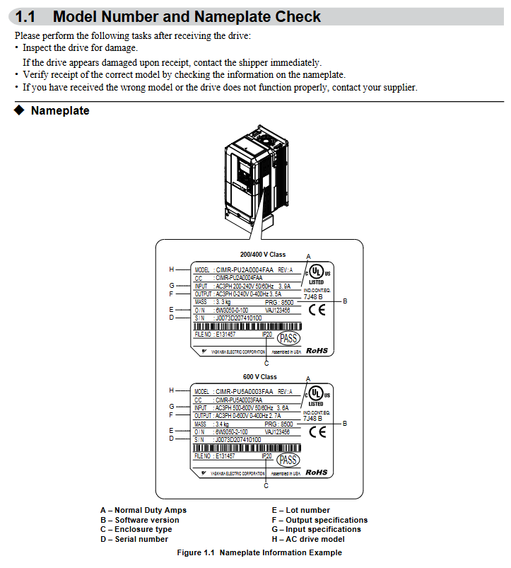
Model coverage:
200 V Class (three-phase): Models 2A0004~2A0415, suitable for motor power of 0.75~175 HP, rated output current of 3.5~415 A;
400 V Class (three-phase): Models 4A0002~4A1200, suitable for motor power of 0.75~1000 HP, rated output current of 2.1~1200 A;
600 V Class (three-phase): models 5A0003~5A0242, suitable for motor power of 1~250 HP, rated output current of 2.7~242 A;
All models are labeled with "ND" (Normal Duty) and are designed specifically for variable torque loads on fans and pumps.
Core features: Support preset application parameters, Auto Tuning, PID closed-loop control, EZ sleep/wake energy-saving function, multiple braking methods (DC injection braking, dynamic braking), in compliance with UL, cUL, CE, RoHS 2 and other certification standards.
Mechanical Installation: Environmental Requirements and Operating Standards
1. Installation environment requirements (must be strictly followed)
Specific requirements for environmental dimensions: Remarks
Temperature IP20/NEMA 1 model: -10~+40 ℃; IP00/Open Type models: -10~+50 ℃. If the temperature exceeds+50 ℃, the capacity needs to be reduced to avoid severe temperature fluctuations
Humidity ≤ 95% RH, no condensation to prevent moisture and short circuit of the circuit board
Altitude ≤ 1000 meters (without capacity reduction); 1000-4000 meters: For every 1000 meters increase, the capacity decreases by 8%. In high-altitude areas, the heat dissipation capacity needs to be evaluated
Avoid direct contact with vibration sources at frequencies of 10-20Hz (9.8m/s ²) and 20-55Hz (5.9m/s ²)
The surrounding environment should be free of dust, oil mist, metal debris, corrosive gases, and direct sunlight. A clean environment is preferred, and suitable protective kits should be selected for harsh environments
2. Installation method and spacing requirements
Installation direction: Only supports vertical installation. Tilting installation can cause poor heat dissipation and damage to internal components.
Single installation spacing:
Up and down direction: at least 50mm (heat dissipation space);
Left and right direction: at least 30mm (wiring and heat dissipation);
Rear: It should be tightly attached to the enclosed surface to avoid the dispersion of cooling airflow.
Multiple units installed side by side:
Only low-power models (such as 2A0004~2A0081, 4A0002~4A0044) are supported, and the parameter L8-35=1 (Side by Side mode) needs to be set;
The minimum spacing is 2mm, but capacity reduction needs to be considered and aligned with the top of the model to facilitate fan replacement.
3. Precautions for lifting and protection
Use of lifting rings: Some high-power models (such as 2A0360, 4A0250~4A1200) are equipped with lifting rings, and vertical lifting is only used for temporary installation. Long term suspension is prohibited; The lifting of 4A0930/4A1200 requires a suspension angle of ≥ 50 ° to avoid overloading of the lifting ring.
Protection level maintenance: After removing the top protective cover or bottom conduit bracket of IP20/NEMA 1 models, only IP20 protection is retained and NEMA 1 certification is lost.
Electrical installation: wiring specifications and safety requirements
1. Main circuit wiring (prevention and control of core risk points)
Terminal differentiation:
Input terminals (R/L1, S/L2, T/L3): connected to a three-phase power supply, matching the voltage level of the frequency converter (such as 200V level connected to 200-240V, 400V level connected to 380-480V);
Output terminals (U/T1, V/T2, W/T3): connected to the motor, the phase sequence determines the motor direction, and reverse can exchange any two phases ();
Brake terminals (B1, B2): only connect brake resistors/brake units, strictly prohibit connecting other devices.
Wiring requirements:
Wire specifications: Choose according to the rated current of the model. For example, the 2A0004 model uses 14AWG wire for the main circuit, and the 4A1200 model uses 300kcmil wire, and requires the use of ring crimping terminals (UL/cUL certification requirements);
Tightening torque: M4 screws 1.2-1.5N · m, M8 screws 9.9-11N · m. Overtightening may damage the terminals;
Grounding: separate grounding, not sharing grounding wire with high current equipment such as welding machines; The cross-sectional area of the grounding wire for models 4A0414 and above is ≥ 10mm ² (copper) or 16mm ² (aluminum).
2. Control circuit wiring (anti-interference and functional configuration)
Digital input (S1~S8):
Support sinking/sourcing mode, switched through SC-SP/SC-SN jumper, default sinking mode;
Default functions: S1 (forward rotation), S2 (reverse rotation), S3 (external fault), S4 (fault reset), customizable through H1 series parameters.
Analog inputs (A1~A3):
A1/A3 default voltage input (0~10V), A2 default current input (4~20mA), switched through jumper S1;
- ABB
- General Electric
- EMERSON
- Honeywell
- HIMA
- ALSTOM
- Rolls-Royce
- MOTOROLA
- Rockwell
- Siemens
- Woodward
- YOKOGAWA
- FOXBORO
- KOLLMORGEN
- MOOG
- KB
- YAMAHA
- BENDER
- TEKTRONIX
- Westinghouse
- AMAT
- AB
- XYCOM
- Yaskawa
- B&R
- Schneider
- Kongsberg
- NI
- WATLOW
- ProSoft
- SEW
- ADVANCED
- Reliance
- TRICONEX
- METSO
- MAN
- Advantest
- STUDER
- KONGSBERG
- DANAHER MOTION
- Bently
- Galil
- EATON
- MOLEX
- DEIF
- B&W
- ZYGO
- Aerotech
- DANFOSS
- Beijer
- Moxa
- Rexroth
- Johnson
- WAGO
- TOSHIBA
- BMCM
- SMC
- HITACHI
- HIRSCHMANN
- Application field
- XP POWER
- CTI
- TRICON
- STOBER
- Thinklogical
- Horner Automation
- Meggitt
- Fanuc
- Baldor
- SHINKAWA
- Other Brands
- UniOP
- KUKA
- Iba
-
 PILZ PNOZ M0P Safety Relay 773110
 -
 Fanuc A20B-2101-0820 Control Circuit Board
 -
 Siemens 3SK1121-1AB40 Safety Relay
 -
 Pilz 772120 Safety Relay Expansion Module
 -
 Mitsubishi AX71 Input Module 16 Point
 -
 Siemens 6ES7350-1AH03-0AE0 S7-300 Extension
 -
 Fanuc A16B-3200-0010 CPU Card
 -
 Omron CJ1W-SCW22 Serial Communication Unit
 -
 Siemens 6SN1118-0DM21-0AA0 Control Module
 -
 Renishaw PHC10-3PLUS Controller Module
 -
 ABB AX521 1SAP250100R0001 Module
 -
 Omron NA5-9W001B-V1 PLC Module HMI
 -
 Infineon FF1000R17IE4 IGBT Power Module
 -
 Omron CJ1W-DA08C Analog Output Module
 -
 Omron CJ1G CPU45H CJ1H CPU66H CJ1G CPU43H CJ1W PA202
 -
 Omron CJ1W-DA041 Analog Output Module
 -
 Inductotherm 170-8031 PLC Control Module
 -
 Fuji Electric FPB56HR-A10 Programmable Logic Controller
 -
 Siemens 6SN1145-1BA01-0BA1 Infeed Regenerative Module
 -
 PILZ 777949 PSWZ X1P Safety Relay
 -
 Schneider 140NOM25200 DIO Head-end Adaptor
 -
 Siemens PXC5.E003 Controller BPZ
 -
 Schneider BMXEHC0800 Fast Counting Module 10kHz
 -
 Schneider BMXART0814 Isolated Thermocouple Inputs
 -
 Schneider BMXNOE0100 Ethernet Module 10 100 RJ45
 -
 LMX06-NS05 Sensor Industrial Proximity Switch
 -
 Siemens 6SN1145-1BB00-0FA1 Power Supply 156kW
 -
 Pro-face GP2500-LG41-24V HMI Graphic Panel
 -
Keyence CV-3001 Vision System CV3OO1
-
 Siemens 6GK5204-2BB10-2AA3 Ethernet Module
 -
 Pro-face PFXSP5500TPD 10.4in HMI LCD Display
 -
 Eu Automation 140DRA84000 Modicon Quantum Module
 -
 Siemens 6FC5210-0DF31-2AA0 Sinumerik PCU 50.3-C
 -
 Siemens 6SL3040-1NC00-0AA0 Sinumerik NX10.3 Extension
 -
 Gould AS-884A-111 Modicon 884 Controller
 -
 Allen Bradley 1336E-BRF30-AA-EN-HA2-L5 Impact Drive
 -
 Siemens 6FC5110-0BB02-0AA1 Sinumerik 840D CPU Card
 -
 Pilz 773500 PNOZmulti Expansion Module
 -
 Siemens 6ES7350-1AH03-0AE0 S7-300 Counter Module
 -
 Siemens 6FC5110-0DB01-0AA1 Sinumerik 840D Card
 -
 HPM 1D703-0040 Command 9000 VGA Console Board
 -
 OMRON CJ1W-PTS52 Temperature Unit
 -
 Sacs Technique PCD4.M12 Module
 -
 OMRON CJ1M-CPU11-ETN Ethernet CPU
 -
 OMRON CJ1M-CPU23 PLC CPU Unit
 -
 OMRON NX-SID800 Safety Input Unit
 -
 GE Fanuc Series 90-30 PLC
 -
 OMRON CJ1W-NCF71 Position Control
 -
 OMRON CJ1W-AD081-V1 Analog Input
 -
 OMRON FZ-S2M Vision Camera
 -
 OMRON R88D-UEP20V Servo Driver
 -
 OMRON F500-C10-ETN Vision Controller
 -
 OMRON CS1W-DA041 Analog Output Module
 -
 PRO-FACE GP577R-TC41-24VP HMI Panel
 -
 TRUTZSCHLER RAK 1 492-58.430.000 PLC Module
 -
 OMRON NX-OD5256 Output Module
 -
 Siemens 6AG1214-1AG40-4XB0 PLC
 -
 OMRON CJ1W-AD081-V1 Analog Unit
 -
 OMRON C500-CPU11-E PLC CPU
 -
 OMRON NX-ECC201 EtherCAT Coupler
 -
 OMRON F300-A20S Camera Interface
 -
 Mitsubishi 80173-109-01 PLC Module
 -
 Fanuc A16B-2200-0141 PCB Board
 -
 Lenze EPL10200 PLC Module
 -
 OMRON CJ1M-CPU13 PLC CPU Unit
 -
 Yaskawa SGMPH-04AAA61D-OY Motor
 -
 OMRON NX-SOD400 Safety Output
 -
 Control Techniques V1800 Flux Vector Drive
 -
 Yaskawa SGDH-04AE-OY Servo Drive
 -
 OMRON NT-DRT21 DeviceNet Interface
 -
 OMRON C500-RM001-V1 Remote I/O Master
 -
 OMRON C500-AD006 Analog Input Module
 -
 OMRON 3G3MV-A4055 Inverter Drive
 -
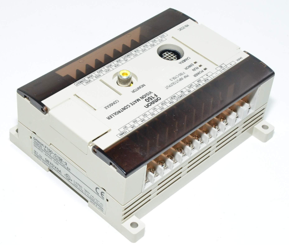 OMRON F150-C15E-3 Vision Mate Controller
 -
 OMRON CS1G-CPU44H PLC CPU
 -
 GE Fanuc DS6800CCIE1E1D CPU Module
 -
 Omron CP1L-M30DR-A PLC CP1W-CIF01 CPU Unit
 -
 Heraeus 585923 2M130 M8 Electrode Assembly Sensor
 -
 Omron C40P-EDT1-D C Series PLC Controller
 -
 Yaskawa SGMGH-09DCA6F-OY Servo Motor SGDH Driver
 -
 Datalogic SG-BWS-T4-MT Safety Control Unit Category 4
 -
 Pro-face PFXLM4301TADDC HMI Controller LT-4301M
 -
 Mitsubishi FX1N-60MR-DS PLC Main Unit 60 I/O
 -
 Omron NJ501-1320 Sysmac Database Connection CPU
 -
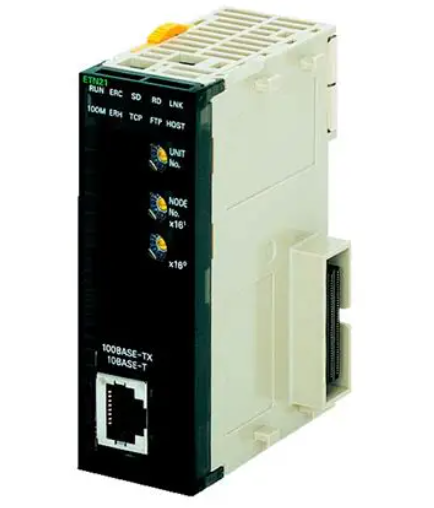
 Omron CJ1W-ETN21 Ethernet Unit CJ Series Module
 -
 Siemens 6ES7517-3AP00-0AB0 CPU 1517-3 PN/DP
 -
 Pasaban MTC-3052 Fast I/O PLC Module
 -
 Mitsubishi FX3U-128MR/ES-A PLC
 -
 OMRON CS1W-CLK21 Controller Link Unit
 -
 Yokogawa ADV151-E63 Digital Input Module
 -
 Allen Bradley MPL-B680B-M-X227 Motor
 -
 OMRON CJ1W-NC413 4-Axis Position Unit
 -
 Yaskawa SGMGH-30DCA6H-OY Servo Motor
 -
 Bosch 1070075337-101 Output Card
 -
 OMRON CQM1-CPU45-EV1 PLC CPU Unit
 -
 Siemens 6SE7090-0XX84-0AG1 CU3 Control Module
 -
 OMRON CQM1-TC101 Temperature Control Module
 -
 MOOG OEM-1030-422 Wind Energy PLC Controller
 -
 OMRON ZFX-C15 Vision Sensor
 -
 Square D 8702SCO2V02 Reversing Contactor
 -
 OMRON C20-LK201-EV1 PLC Link Adapter
 -
 OMRON NB7W-TW01B HMI PLC
 -
 Siemens 7ME6920-1AA10-1AA0 Flow Transmitter
 -
 Allen Bradley 1791-8BR Block I/O Module
 -
 OMRON CQM1-AD041 Analog Input Module
 -
 OMRON CJ1M-CPU21 PLC Module
 -
 Omron Z500-MC10E-001 Laser Profile Controller
 -
 Omron NA5-7W001B-V1 NA Series Programmable Terminal HMI
 -
 Allen-Bradley 1606-XLS960EE Power Supply 960W 24VDC
 -
 GE DS3800NEPB1F1E Power Excitation Board Mark IV
 -
 Yaskawa SGDH-04AE-OY Sigma-II Servo Drive 400W
 -
 Allen-Bradley 2711P-RBT7 PanelView Plus 7 Bezel
 -
 CCS PD3-3024-3-EI Digital Control Unit 3 Channel
 -
 Yaskawa CPU301 MP3300 Controller JAPMC-CP3301-2-E
 -
 Omron C40P-EDR-D PLC C Series P Type Controller
 -
 Omron NX-SID800 Safety Input Unit 8 PNP 24VDC
 -
 ABB SCC-C 23070-0-10232110 gas cooler
 -
 Sick LGTN101-521 CPU Module
 -
 Okuma 1911-2836 PLC Circuit Board
 -
 Mitsubishi Melsec PM-120M PLC
 -
 Omron F210-C15 Vision Mate Controller System
 -
 Siemens 7ML5110-1GD07-4AF3 Ultrasonic Level Gauge
 -
 ABB Pluto S46 V2 Safety Relay
 -
 Omron Z3RN-5A Optical Serial Link
 -
 Omron R7D-APA3H 30W Servo Drive
 -
 Giddings Lewis 502-03638-41R3 PLC Processor
 -
 Omron SCY-P1 Sequencer Controller
 -
 Siemens C98043-A7002-L1-13 PCB Board


