
ABB Panel 800 Version 6 PP885 Hardware and Installation
ABB Panel 800 Version 6 PP885 Hardware and Installation
Product positioning: Panel 800 Version 6 PP885 is an operation panel designed for human-computer interaction scenarios, suitable for industrial control fields. It can be connected to automation equipment such as PLCs, servo systems, and drives to achieve functions such as text display and control, dynamic indication, time channel management, alarm processing, and formula management.
Safety precautions
(1) General safety requirements
Preparation: Installation personnel, equipment owners, and operators must read and understand this installation manual; Carefully read the safety precautions and check if there is any transportation damage to the delivered products. If there is any damage, immediately notify the supplier; Suppliers are not responsible for modified, altered, or modified equipment and are only allowed to use parts and accessories that meet the supplier's specifications.
Operation specifications: Before installing, using or repairing the operation panel, carefully read the installation and operation instructions; It is strictly prohibited for liquids, metal debris, or wiring debris to enter any opening of the operation panel to prevent fire or electric shock; Only qualified personnel are allowed to operate the control panel.
Storage and special case handling: The operation panel should be stored within the recommended temperature range. If the temperature is too low, it may cause the LCD display liquid to solidify, and if it is too high, it may cause isotopic phenomena; LCD display liquid contains highly irritating substances. If it comes into contact with the skin, immediately rinse with plenty of water. If it comes into contact with the eyes, open the eyes and rinse with plenty of water before seeking medical attention; The illustrations in the manual are only for illustration purposes. Due to the existence of multiple variables in the installation scenario, the supplier is not responsible for the actual use based on the illustrations; Suppliers do not guarantee that the operation panel is suitable for specific applications, nor are they responsible for product design, installation, or operation; It is recommended to perform at least one power on/off operation on the control panel before installing any components/cards or connecting external devices (such as serial devices).
(2) Disposal requirements under WEEE regulations
EU professional users: If you need to dispose of electrical and electronic equipment (EEE), you need to contact the distributor or supplier for further information.
Non EU country users: If you need to dispose of this product, you need to contact the local regulatory authority or distributor to understand the correct disposal method.
(3) UL and cUL installation requirements
Usage environment and power supply: The equipment is only suitable for Class 2 non hazardous locations; The combination of devices in the system must undergo inspection by the local regulatory authorities during installation; All devices must be powered by a Class 2 power supply, and disconnection is prohibited when powered on.
Expansion unit and battery: Only UL and cUL certified expansion units are allowed to be connected to ports labeled "EXPANSION", and there are currently no such evaluated or approved units for use; Before replacing the expansion unit, it is necessary to ensure that the power is turned off or that the area is non hazardous; The product contains batteries and can only be replaced in known non hazardous areas. BR 2032 batteries must be used, as using other types of batteries may pose a risk of fire or explosion; Improper handling of batteries may cause explosions. Charging, dismantling, or putting them into fire is prohibited.
Installation and wiring: can only be used on flat surfaces of Class 4 indoor enclosures; Only copper wires with a minimum temperature rating of 75 ° C are allowed to be used; The wiring connection of the power cord connector must comply with the cable and torque specifications (the torque corresponding to the wire size is 3.5 pounds per inch); These devices are Class 2 power supply programmable controllers (industrial PCs) suitable for industrial control equipment, intended for (front) panel installation (Class 1 and Class 4X, indoor use only); The protection level of the shell should be at least IP20, but it needs to reach IP54 when installed in the equipment.
(4) Safety requirements during installation
Installation environment: The operation panel is designed for fixed installation on a flat surface, and the installation environment must meet the conditions of no high explosion risk, no strong magnetic field, no direct sunlight, and no drastic temperature changes.
Installation operation specifications: Install the operation panel according to the attached installation instructions and perform grounding treatment; Only qualified personnel are allowed to install the operation panel; Separate the layout of high-voltage cables, signal cables, and power supply cables; Before connecting the power socket, it is necessary to confirm that the power voltage and polarity are correct; Peripheral devices need to be suitable for the application scenario and installation location.
Special area installation: In Zone 2 environment, the equipment needs to be installed in a casing with a protection level of not less than IP54 and not more than IP65 (in accordance with IEC/EN 600079-0 standard), and the IP level of the equipment is limited by the IP level of the installed casing; In the 22 zone environment, the equipment needs to be installed in an enclosure with a protection level of not less than IP64 and not more than IP65 (in accordance with IEC/EN 600079-0 standard), and the IP level of the equipment is also limited by the IP level of the enclosure.
(5) Safety requirements during use
Keep the operation panel clean; Emergency stop and other safety functions shall not be controlled through the operation panel; Do not use excessive force or sharp objects when operating the touch screen.
(6) Service and Maintenance Security Requirements
Only qualified personnel are allowed to carry out repairs; Follow the agreed warranty terms; Before performing any cleaning or maintenance operations, the power connection of the equipment must be disconnected; Clean the display screen and surrounding front cover with a soft cloth and mild cleaning agent; Improper battery replacement may result in explosion. Only use batteries recommended by the supplier. During the warranty period, batteries must be replaced by authorized ABB service centers.
(7) Dismantling and scrapping safety requirements
The operation panel or its components must be recycled and disposed of in accordance with local regulations; Components such as lithium batteries, electrolytic capacitors, and displays in the equipment contain substances that may be harmful to health and the environment.
(8) Air appears in the touch screen
The layered structure of the touch screen contains air, and in rare cases, bubbles may appear, which only affects the appearance and does not affect any function of the operation panel. This phenomenon may occur under specific environmental conditions such as temperature, humidity, and air pressure.
Installation related
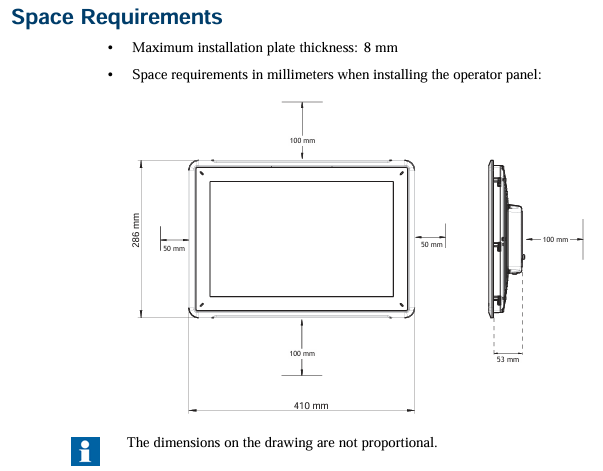
(1) Space requirements
Installation plate thickness: The maximum installation plate thickness is 8mm.
Size requirements: When installing the operation panel, the space requirements in all directions (unit: mm) are as follows: 100mm (partial area), 286mm (partial area), 50mm (both sides), 53mm (partial area), 410mm (overall relevant dimensions). Please refer to the outline drawing in the manual for accurate installation dimensions, which are not drawn to scale.
(2) Installation process
Preparation: Prepare Torx TX7 screwdriver; Unpack and inspect the delivered products. If any damage is found, notify the supplier; During installation, place the control panel on a stable surface to prevent it from falling and causing damage.
Cutting and fixing of openings: Cut suitable openings for the operation panel according to the opening size in the contour diagram (refer to the "Operation Panel Drawing" and "Technical Data" sections for detailed information); Use M4 Torx screws (specification M4 × 20.7, torque 0.4Nm) to secure the operation panel, ensuring that the built-in bracket is tightly attached to the panel.
Cable connection: Connect the cables in the specified order according to the diagram and the following steps:
Before starting the operation panel, it is necessary to reach the ambient temperature. If condensation occurs, ensure that the operation panel is dry before connecting to the power outlet.
Ensure that the operation panel and controller system have the same electrical grounding (reference voltage level), otherwise communication errors may occur.
Confirm that the power supply voltage and polarity are correct; Separate high-voltage cables from signal cables and power supply cables; Suggest using shielded communication cables.
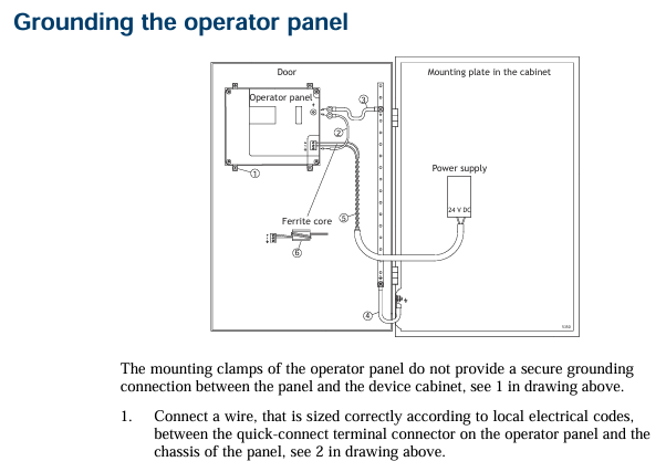
Connect cable A (24V DC); Connect cable B using M5 screws and grounding wire (as short as possible, with dimensions in accordance with local electrical regulations); Connect cable C (Ethernet); Connect cable D (RS232/RS422/RS485), with a recommended cable cross-section of 1.5mm ².
Removal of protective film: Carefully remove the protective film on the operation panel display screen, taking care to avoid static electricity damaging the panel.
(3) Connection with controller
For information on the cables used to connect the control panel to the controller, please refer to the help files of the relevant driver programs.
(4) Other connections and peripheral devices
Cables, peripheral devices, and accessories should be suitable for the application scenario and its environment. For detailed information or suggestions, please consult the supplier.
Technical data
Project parameters
Cover layer Autoflex EBA 180L (see "Chemical Resistance" section for details)
Shell material powder coated aluminum
Communication interface (1) 9-pin D-sub interface, supports RS232 RTS/CTS, chassis mounting female head, with standard locking screw (4-40 UNC)
Communication interface (2) 9-pin D-sub interface, supports RS232 RTS/CTS, chassis mounting female head, with standard locking screw (4-40 UNC)
Store 2GB SSD (NAND Flash) and support formats with a maximum storage capacity of 2GB
1GB of memory (DDR2)
One multi-color indicator light (on-chip integrated)
Lithium battery, model BR 2032 (or CR 2032)
Power consumption 24W
Power input 3.15A slow melting,+24V DC (18-32V DC)
Power compliance CE: The power supply must comply with the requirements of IEC 60950 and IEC 61558-2-4 standards; UL and cUL: The power supply must meet the requirements of Class 2 power supply
Display TFT-LCD with LED backlight, resolution 1280 × 800 pixels, 262k colors
Display performance: brightness of 450cd/m ², horizontal viewing angle of 160 °, vertical viewing angle of 140 °
Backlight lifespan of 50000 hours
Display screen size 331.2 × 207.0mm
Working temperature range -10 ° C to+50 ° C
Storage temperature range -20 ° C to+70 ° C
Working humidity range 5% -85% (no condensation)
CE certification complies with EMC Directive 2004/108/EC+A1:2011
Chemical resistance
(1) Metal casing
Powder coating has almost no or no resistance to the following chemicals at room temperature: concentrated acetic acid, toluene, 30% nitric acid, and 97 octane unleaded gasoline.
(2) Touch screen and covering material
Autoflex EBA 180L: Not tolerant to high-pressure steam above 100 ° C, nor to various chemical substances (specific substance and contact time requirements: some substances may have adverse effects after 10 minutes of contact, please refer to the detailed list in the manual).
Touch screen surface: After exposure to solvents such as toluene, there is no visible change on the touch screen surface of the operation panel (refer to the manual for a detailed solvent list).
Touch screen protective film: It is recommended to use Autoflex EBA 180L protective film (model RX885/893, can be ordered from ABB), and its chemical resistance is detailed in the "Autoflex EBA 180L" section; Like all polyester based films, Autoflex EBA 180L is not suitable for long-term exposure to direct sunlight; The layered structure of the touch screen contains air, and in rare cases, bubbles may appear, which only affect the appearance and not the function, and may occur under specific environmental conditions.
Operation panel drawing
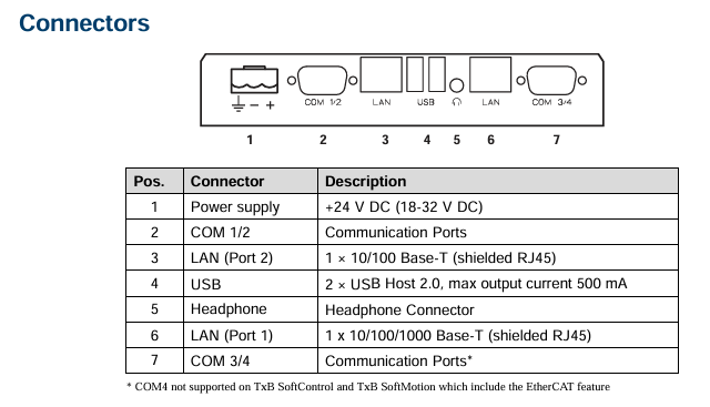
(1) Connector
The drawings indicate the positions of connectors and related interfaces (such as COM1/2, LAN, USB, C LAN, COM3/4, etc.), but COM4 is not supported on TxB SoftControl and TxB SoftMotion that include EtherCAT functionality. For detailed interface layout and pin definitions, please refer to the illustrations in the manual.
(2) Communication port
Port function and connection: The communication port supports protocols such as RS232, RS422, RS485, etc. Some port pins are defined as follows (example): RS232 TxD, RS422 Rx+, GND, RS422 Tx -, RS485 Tx -/Rx -, etc. (detailed pin allocation reference manual diagram); COM4 is not supported on specific models.
Special connection requirements: If two communication ports need to be used on the same physical port, Y-shaped distribution cable TK860V001 (part number 3BSE069476R1) must be used.
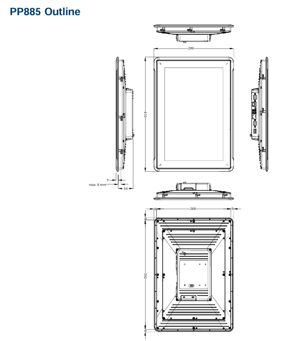
(3) PP885 contour
The contour diagram indicates the key dimensions of the operation panel (unit: mm), such as 286mm (partial length), maximum 8mm (related to installation plate thickness), 54mm (partial height), 268mm (partial length), 392mm (partial length), 410mm (overall length), etc. For detailed dimensions, please refer to the contour diagram in the manual.
(4) Environmental temperature
Temperature influencing factors: The maximum ambient temperature of the operation panel is specified in the specifications. Here, the ambient temperature refers to the temperature at which the electronic components of the operation panel are cooled inside the equipment cabinet; In most cases, the ambient temperature of the control panel is much higher than that of the equipment cabinet; If the cabinet is high and contains multiple heating devices, the temperature at the top of the cabinet will be much higher than the expected temperature rise. All electronic devices are sensitive to heat, and the lifespan of electrolytic capacitors will be reduced by half with an increase of 8-10 ° C in temperature, and by a quarter with an increase of 15-20 ° C, and so on.
Temperature control suggestion: Rittal provides a solution for estimating the expected average temperature of the cabinet and various cabinet temperature control systems; The radiant heat value of enamel steel cabinets is 5.5W/(m ² ·° C); Installing fans inside the cabinet can make the temperature uniform, and the cooling effect of flowing air is much better than that of static air; The fan should be installed in a cooler area to blow cold air towards the control panel. If the fan is installed at the top and draws heat absorbing air upwards, it will cause the ambient temperature of the fan to rise and shorten its lifespan; The net power consumption of the operation panel can be estimated by multiplying the power supply voltage by the operating current of the operation panel (assuming that all power supply is converted into heat).
(5) Security
Power supply safety: Most operation panels are powered by 24V DC; If using a power supply that meets safety standards and only supplies power to the operation panel, there are no safety issues; If a 24V power supply is supplying power to other devices at the same time, caution should be taken. In the event of a potential short circuit between 230V AC and 24V DC on the control panel, insulation that meets safety requirements is not available. Assuming that 24V power supply is safe (such as SELV that complies with EN 60950 (anti electric shock) and UL 950 standards).
Potential risks and solutions: In small controllers, if the 24V relay contacts are mixed with the 230V AC relay contacts, it may compromise the safety of 24V DC power supply. It is necessary to check whether the electrical clearance and creepage distance between 24V DC and 230V AC comply with EN 60950 or UL 950 standards. If they do not comply, a separate 24V power supply needs to be configured for the operation panel; If the distance between the contacts of 24V DC and 230V AC relays is large enough, the same 24V device can be used to power all devices; There are three advantages to grounding a 24V power supply with 0V: improving safety (if there is a connection error or short circuit between the 0V (24V) and 230V phase lines, the 24V power supply will not be charged), guiding transient signals on the 24V power supply to the ground, and avoiding the 24V power supply being at a high potential relative to the ground (which is prone to occur when static electricity is high).
(6) Galvanic isolation
Isolation feature: The operation panel has electrical isolation for 24V DC power supply, but there is no electrical isolation between communication ports such as RS232, RS422/485, and USB. Only Ethernet connections have electrical isolation.
Grounding and communication risks: When the PC is connected to the operation panel, the internal 0V (GND) of the panel is connected to the protective ground through the PC; The shielding layer of multiple USB devices may be connected to the protective ground, for example, when inserting USB flash drives, keyboards, and other devices, the 0V (GND) of the operation panel will be connected to the protective ground; If multiple devices have 0V and ground connections, and are connected to different grounding points, it is highly likely to cause problems. Grounding current may pass through communication cables, controller backplanes, and the interior of the operation panel, leading to errors.
Improvement measures: External devices can be used to improve communication and achieve electrical isolation, such as Westermo's industrial standard isolator (also isolated from 24V DC feed); It is necessary to ensure that the 24V power supply of the external isolator is not connected to any communication output terminal. If it is not 100% isolated from the 24V power supply, the interference of 0V on the 24V side and the grounding current will interfere with communication. Such equipment may solve one problem but cause bigger problems. Improper installation may temporarily work normally, but faults may occur when connecting other devices.
(7) RS485 cable and bus terminal
Cable requirements: If maximum transmission distance and maximum transmission speed are required, shielded twisted pair cables should be used, with a mutual capacitance not exceeding 52.5pF/m and a cable cross-sectional area of at least 0.25mm ² (AWG 24); The communication reference voltage of 0V should be included in the cable, and bidirectional communication requires the use of two pairs of wires (one pair for communication and one pair for 0V).
Shielding and termination: The shielding layer needs to be grounded at one end, and the other end is usually also grounded. However, when long-distance transmission or grounding potential is different, the shielding layer should be grounded through a 0.1 μ F/250V plastic capacitor to prevent grounding current from being generated in the braided shielding layer; Different manufacturers have different systems for bus terminals. Depending on the design of the receiving end, the bus wires may be at the same level or require pull-up/pull-down resistors to ensure that no error signals are detected when the bus is in idle mode (all transmitters are disconnected).
- OMRON
- ABB
- General Electric
- EMERSON
- Honeywell
- HIMA
- ALSTOM
- Rolls-Royce
- MOTOROLA
- Rockwell
- Siemens
- Woodward
- YOKOGAWA
- FOXBORO
- KOLLMORGEN
- MOOG
- KB
- YAMAHA
- BENDER
- TEKTRONIX
- Westinghouse
- AMAT
- AB
- XYCOM
- Yaskawa
- B&R
- Schneider
- KONGSBERG
- NI
- WATLOW
- ProSoft
- SEW
- ADVANCED
- Reliance
- TRICONEX
- METSO
- MAN
- Advantest
- STUDER
- DANAHER MOTION
- Bently
- Galil
- EATON
- MOLEX
- DEIF
- B&W
- ZYGO
- Aerotech
- DANFOSS
- Beijer
- Moxa
- Rexroth
- Johnson
- WAGO
- TOSHIBA
- BMCM
- SMC
- HITACHI
- HIRSCHMANN
- Application field
- XP POWER
- CTI
- TRICON
- STOBER
- Thinklogical
- Horner Automation
- Meggitt
- Fanuc
- Baldor
- SHINKAWA
- Other Brands
- UniOP
- KUKA
- Iba
- Beckhoff
-
 Basler DECS-200-2L Digital Excitation Control
 -
 Basler BE1-47N Voltage Phase Sequence Relay
 -
 Basler AEC63-7 Analog Excitation Controller 220-277V
 -
 Basler BE1-50/51B-107 Overcurrent Relay
 -
 Basler Electric BE1‑32R BE1‑E1P‑BON0F Protective Relay
 -
 Basler BE1-25 Solid State Time Overcurrent Relay M1EA6PA5S1F
 -
 Basler MVC 232 Manual Voltage Control Module 90 37000 103 60VAC 55VDC
 -
 Basler RAL6144-16GM Racer GigE Line Scan Camera
 -
 Basler SSR 63-12 Static Voltage Regulator
 -
 Basler BE1-51A Overcurrent Relay
 -
 Basler BE1-87T Solid State Protective Relay
 -
 Basler SR4A2B01B3A Static Voltage Regulator
 -
 Basler SSR 32-12 Static Voltage Regulator
 -
 Basler TRR00696 Transformer 1KVA 115V
 -
 Basler DECS-100-B15 AVR Replacement
 -
Basler BE1-27 Under-Voltage Relay
-
 Basler ACA2000-50GM Interface Module
 -
 Basler AEC63-7 Analog Excitation Controller
 -
 Basler PRS 250 Veri-Sync Relay
 -
 Basler SR4A-2B15B3A Static Voltage Regulator
 -
Basler BE1-32R Power Relay
-
Basler SR8A-2B06B3E Static Voltage Regulator
-
Basler BE1-81 O/U Frequency Relay
-
 Basler BE1-51A-K2E-W6M-B1N0F Overcurrent Relay
 -
Basler BE1-851 Overcurrent Relay G3A1S1 – 48-125V AC/DC
-
 Basler BEI-51 Overcurrent Relay – NSN 5945-01-293-2363
 -
Basler Electric L301KC Protective Relay – L301KC
-
 Basler DECS-100-B15 Automatic Voltage Regulator – Generator AVR
 -
 Basler SR4A-2B15B3A Static Voltage Regulator – SR4A2B15B3A
 -
 Basler UF 312 Under Frequency Protective Module – 9094700100
 -
Basler Electric MVC 232 Manual Control Module – 60VAC 55VDC 20A
-
Basler PRS 250 Veri-Sync Relay – Generator Synchronizing Relay
-
 Basler DECS-100-A05 Digital Regulator Review
 -
 Basler AEM-2020 Analog Expansion Module Specs
 -
 Basler DECS-100-B15 Digital Excitation Specs
 -
Basler Electric 9125600106 Regulator Component
-
Basler BE1-51A-K1E-W6M-B1N0F Overcurrent Relay
-
 Basler MVC-301 MVC 300 Excitation Controller
 -
 Basler SSR 32-12 Static Voltage Regulator
 -
 Basler 9-2849-00-101 Control Module
 -
Basler BE1-51A Overcurrent Relay
-
 Basler BE1-51/27R Overcurrent Relay
 -
 Basler BE1-51 Overcurrent Relay
 -
 Basler SR8A-2B15B3A Static Voltage Regulator
 -
 Basler BE32965001 Transformer and Timer Board
 -
 Basler 9174700100 EL200-7 Excitation Limiter
 -
 Basler BE2000E AVR Voltage Regulator
 -
Basler BE1-87G Differential Relay
-
 Basler BE21834001 Generator Control Module
 -
Basler DECS-100-B15 AVR
-
 Basler D90 96801 100 PCB Card
 -
 Basler XR2002F Voltage Regulator (110 VAC, 48-480 Hz)
 -
 Basler SR8A-2B14B3A Regulator
 -
 Basler 9561500100 Module
 -
 Basler DECS-400 BE1-11 System
 -
 Basler DECS-100-B15 Excitation Control
 -
 Basler SCP 210 Frequency Controller
 -
Basler SR4A-2B15B3A Static Voltage Regulator
-
Basler BE1-32R Power Relay
-
 Basler PIA2400-17GM Power Interface Adapter
 -
 Basler MVC 232 Manual Voltage Control Module
 -
 Basler SSR 32-12 Static Voltage Regulator
 -
Basler 5MW AVR Generator Voltage Regulator
-
 Basler VR63-4B Voltage Regulator
 -
Basler DECS-100-A05 AVR for Engine Generator
-
Basler DECS-100-B15 Automatic Voltage Regulator
-
Basler BE1-32R Directional Power Relay
-
Basler BE1-87B Differential Relay
-
 Basler UFOV 260A Protective Module
 -
 Basler 9-2614-02-100 PCB Rev M
 -
Basler DECS-100-B15 Digital AVR
-
 Basler 9284900103 PS DECS-400N
 -
 Basler D4N3H1U Intertie Protection
 -
 Basler DECS-100-B15 A15 AVR
 -
 Basler KR4F Voltage Regulator
 -
 Basler BE26434 T14 Transformer
 -
 Basler SR8A-2B15B3A Regulator
 -
 Westinghouse 774B472A12 AR Relay
 -
Basler DECS-100-B15 AVR
-
Basler XR2002F Regulator 110V
-
Basler SR125-E Static Regulator
-
Basler SSR 125-12 Regulator
-
Basler MOC2599 Motor Pot
-
 Basler BE1-DFPR Feeder Relay
 -
 Basler CBS 305 Current Boost
 -
Basler BE1-25 AutoSync
-
Basler MVC 300 Voltage Control
-
 Basler BE3-25A AutoSync
 -
 Basler KR7FF Static Regulator
 -
Basler 90-49000-100 Regulator
-
 Basler 880 kVA Dry Type Transformer Specs
 -
Basler Electric BE1-25 Sync-Check Relay Specs
-
 Basler SSR 125-12 Voltage Regulator Specs
 -
 Basler Electric BE1-851 Overcurrent Relay Review
 -
Basler Electric 149D930G02 Control Sub-Assembly
-
 Basler Electric BE1-81O/UT Frequency Relay Specs
 -
 Basler Electric BE1-51/27C Overcurrent Relay
 -
 Basler Electric 149D956G02 Industrial Component
 -
Basler Electric BE1-51A Overcurrent Relay Specs
-
 Basler Electric BE1-40Q Loss of Excitation Relay
 -
Basler DECS-200 Excitation Control System
-
 Basler DECS-200 Voltage Regulator 56-277V AC / 125V DC
 -
Basler BE1-87T Transformer Differential Relay
-
 Basler RDP-110-S1 Protection Relay
 -
 Basler BE1-700V Digital Protective Relay
 -
 Basler BE1-951 Overcurrent Protection System
 -
 Basler DECS-300 Digital Excitation Control
 -
 Basler DECS-200 Digital Excitation Control
 -
 Basler DECS-200-1C Excitation Control System
 -
Basler DECS-200-1L Digital Excitation Control
-
 Basler Electric BE1-GPS Generator Protection System
 -
Basler Electric DECS-200-1C Digital Excitation Controller
-
 Basler Electric DECS125-15 Excitation Control with Power Module
 -
Basler Electric BE1-87G Differential Relay
-
 Basler Electric BE1-11 Protection System I5A3M2P2N0EA00
 -
Basler Electric DECS-200-1C Excitation Control System
-
Basler Electric BE1-11g Generator Protection Relay
-
Basler Electric DECS 125-15-B2C1 V2.0.9 Excitation Control
-
Basler Electric BE1-81O/UT3ED1JA7N2F Frequency Relay
-
Basler Electric BE1-81O/UT3EE1YB7N1F Frequency Relay
-
 Basler Electric DECS-200-1L Digital Excitation Control System
 -
Basler DECS125-15-B2C1 Excitation Control
-
 Basler 9507900205 SSR Retrofit Voltage Regulator
 -
 Basler BE2000E Digital Voltage Regulator
 -
 Basler BE1-GPS Generator Protection System
 -
Basler DECS-250-CN1CN1N Digital Excitation Control
-
 Basler DGC-2020 Genset Controller
 -
Basler BE1-81O UT3ED1LA7N0F Frequency Relay (Variant)


