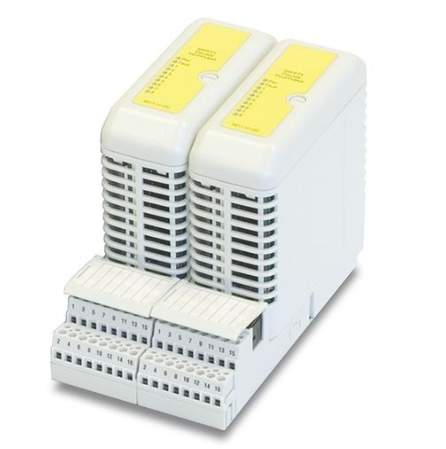
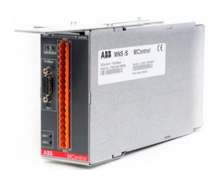
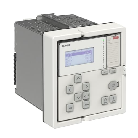
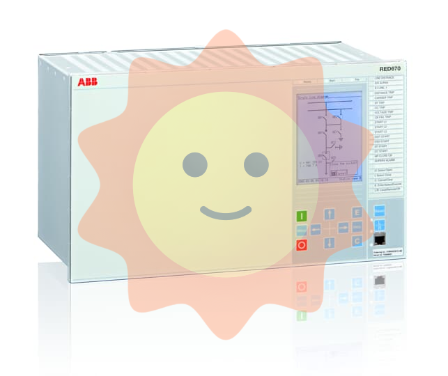
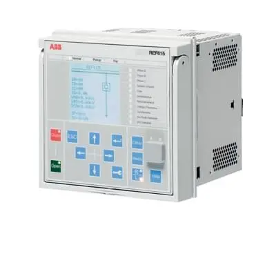
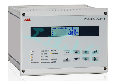
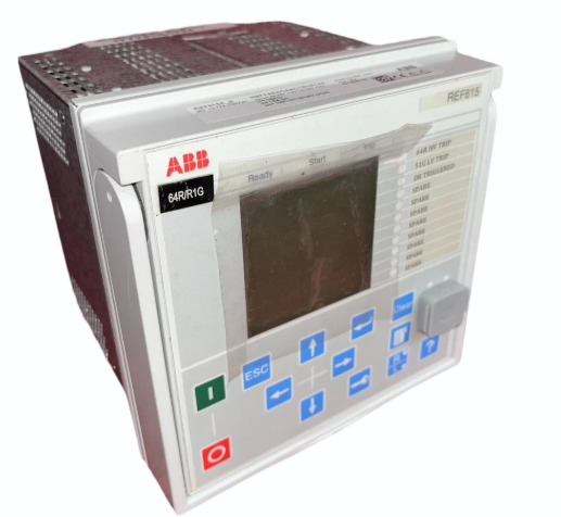
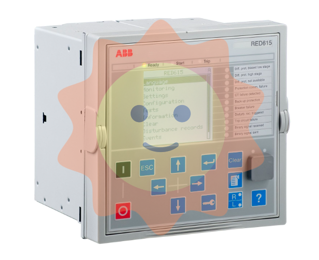
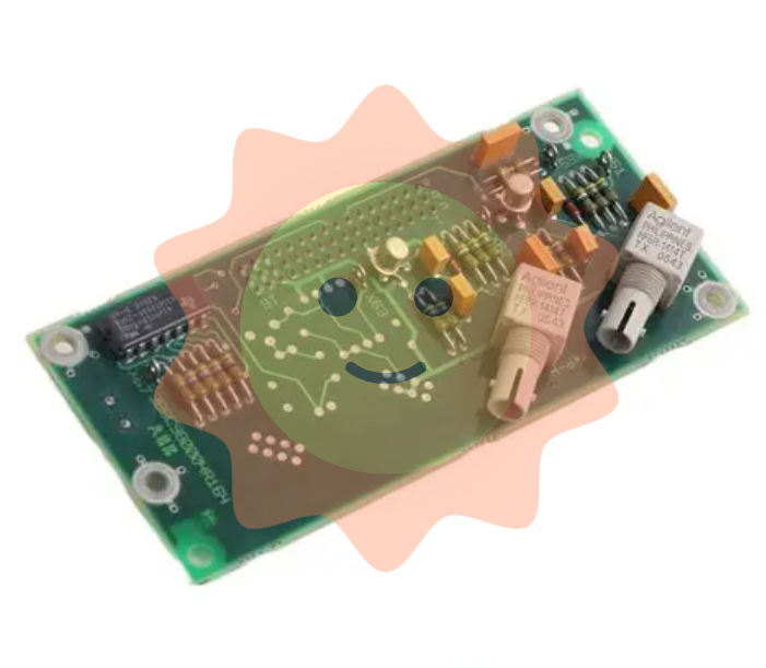
ABB RELION ® 615 series REU615 voltage protection and control relay
Actual accuracy limit coefficient calculation: The actual accuracy limit coefficient (F a) is related to the rated accuracy limit coefficient (F n), CT rated load (S n), CT internal secondary load (S in), and actual external load (S). The calculation formula is:
F a ≈ F n × ∣ S n+S ∣∣ S in+S n ∣ CT selection principle: For non directional overcurrent protection, it is recommended to choose a CT with an actual accuracy limit factor of at least 20. The rated primary current (I 1n) of the CT should meet the requirement of I 1n>I kmax/100 (I kmax is the maximum fault current) to avoid exceeding the thermal and dynamic intensity of the input current measurement of the protective relay.
Suggestion for starting current setting: If I kmin is the lowest current that should be activated during the highest set overcurrent stage, the starting current should be set to:
The current starting value, with a coefficient of 0.7, takes into account protection relay error, CT error, and short-circuit calculation deviation.
2、 Input parameters
(1) Incentive input
Phase current (configuration B)
Terminals: X120:7-8 (IL1), X120:9-10 (IL2), X120:11-12 (IL3)
Can be used for single-phase or two-phase applications, where some excitation inputs can be left vacant, but at least X120:7-8 needs to be connected
Residual current (configuration B)
Terminal: X120:13-14 (Io)
Phase voltage (configuration B)
Terminals: X120:1-2 (U1), X120:3-4 (U2), X120:5-6 (U3)
Phase voltage (configuration A)
Terminals: X130:11-12 (U1), X130:13-14 (U2), X130:15-16 (U3)
SECRSYN1 reference voltage (configuration A)
Terminal: X130:9-10 (U12B)
Residual voltage (configuration A)
Terminal: X130:17-18 (Uo)
(2) RTD/mA input (configuration B optional)
Terminals and corresponding functions:
X130:1-2:mA1(AI1)
X130:3-4:mA2(AI2)
X130:5-6:RTD1(AI3)
X130:7-8:RTD2(AI4)
X130:9-10:RTD3(AI5)
X130:11: RTD channels 1-3 common ground
X130:12: RTD channels 4-6 common ground
X130:13-14:RTD4(AI6)
X130:15-16:RTD5(AI7)
X130:17-18:RTD6(AI8)

- EMERSON
- Honeywell
- CTI
- Rolls-Royce
- General Electric
- Woodward
- Yaskawa
- xYCOM
- Motorola
- Siemens
- Rockwell
- ABB
- B&R
- HIMA
- Construction site
- electricity
- Automobile market
- PLC
- DCS
- Motor drivers
- VSD
- Implications
- cement
- CO2
- CEM
- methane
- Artificial intelligence
- Titanic
- Solar energy
- Hydrogen fuel cell
- Hydrogen and fuel cells
- Hydrogen and oxygen fuel cells
- tyre
- Chemical fiber
- dynamo
- corpuscle
- Pulp and paper
- printing
- fossil
- FANUC
- Food and beverage
- Life science
- Sewage treatment
- Personal care
- electricity
- boats
- infrastructure
- Automobile industry
- metallurgy
- Nuclear power generation
- Geothermal power generation
- Water and wastewater
- Infrastructure construction
- Mine hazard
- steel
- papermaking
- Natural gas industry
- Infrastructure construction
- Power and energy
- Rubber and plastic
- Renewable energy
- pharmacy
- mining
- Plastic industry
- Schneider
- Kongsberg
- NI
- Wind energy
- International petroleum
- International new energy network
- gas
- WATLOW
- ProSoft
- SEW
- wind
- ADVANCED
- Reliance
- YOKOGAWA
- TRICONEX
- FOXBORO
- METSO
- MAN
- Advantest
- ADVANCED
- ALSTOM
- Control Wave
- AB
- AMAT
- STUDER
- KONGSBERG
- MOTOROLA
- DANAHER MOTION
- Bently
- Galil
- EATON
- MOLEX
- Triconex
- DEIF
- B&W
- ZYGO
- Aerotech
- DANFOSS
- KOLLMORGEN
- Beijer
- Endress+Hauser
- MOOG
- KB
- Moxa
- Rexroth
- YAMAHA
- Johnson
- Westinghouse
- WAGO
- TOSHIBA
- TEKTRONIX


Email:wang@kongjiangauto.com

