
TOSHIBA TOSBERT S11 series frequency converter
2. Control circuit wiring
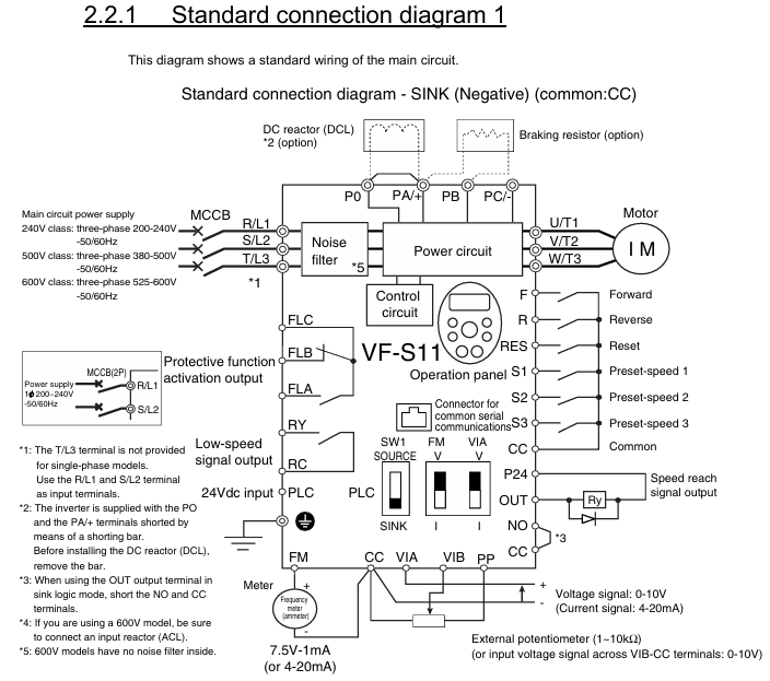
Analog input (AI1/AI2):
Terminal default function configurable function wiring requirements
AI1 0-10VDC (frequency command) 4-20mA (parameter P07.01) Load resistance ≤ 500 Ω, shielded twisted pair (0.5mm ²)
AI2 4-20mA (torque command) 0-10VDC (parameter P07.02) Same as AI1, cable length ≤ 20m
Switching input (DI1-DI6):
Default functions: DI1=forward rotation, DI2=reverse rotation, DI3=multi speed 1, DI4=multi speed 2, DI5=jog, DI6=reset.
Input method: leakage type (default)/source type optional (P06.01), 24Vdc ± 10%, current ≤ 8mA.
Communication interface:
Standard RS485 (terminals A/B), supports MODBUS-RTU, baud rate 9600-115200bps (P20.01).
Optional RS232 module (requires TX/RX/GND terminals) for direct communication with PC.
3. Wiring taboos
Do not connect compensation capacitors at the motor end (which may cause overvoltage tripping).
The distance between the control cable and the main circuit cable should be ≥ 15cm to avoid parallel wiring (reduce EMI interference).
After wiring the IP40 model, it is necessary to check whether the sealing ring is compacted to prevent dust/water vapor from entering.
Operation panel and core operations
1. Analysis of the operation panel
Panel layout (Figure 4-1):
Display: 2-line LCD screen (supports Chinese/English, parameter P00.02 switching), displaying frequency, current, and fault codes.
Buttons: RUN, STOP, MODE, △/▽ (parameter adjustment), ENTER (confirm).
Indicator lights: Power (PWR), Run (RUN), Fault (ALM).
Menu structure: First level menu (monitoring/parameters/faults) → Second level menu (parameter group P00-P29) → Third level menu (specific parameters).
2. Basic operation process (panel control)
Power on standby: Close the MCCB, the PWR light is on, the screen displays "0.0Hz", and there is no ALM alarm.
Frequency setting: Press MODE to select "Panel Control", press △/▽ to set the target frequency (such as 50Hz), and confirm with ENTER.
Start/Stop: Press RUN to start (RUN light on), press STOP to soft stop (deceleration time P03.02 defaults to 3 seconds).
Fault reset: When the ALM light is on, press STOP for 2 seconds to reset after troubleshooting.
3. External/Communication Control Operations
External control: P05.01=1 (external mode), DI1 is connected to the forward switch, AI1 is connected to the potentiometer, and the switch is closed to start.
Communication control: P05.01=2 (communication mode), PC sends instructions through MODBUS (such as writing frequency 0x0001=5000 → 50Hz).
Core functions and parameter configuration
1. Control mode and key parameters
Control mode parameters (P01.01) core parameters applicable scenarios
V/f control 0 P01.02 (V/f curve: 0=linear, 1=square) Fan/pump (variable torque)
Sensorless vector (SVC) 1 P01.04 (vector gain: 0.1-10.0), P04.01 (torque limit: 50-200%) machine tool/conveyor (constant torque)
2. Multi speed and brake control
16 speed operation: P08.01-P08.16 set the 16 speed frequency (0.0-400.0Hz), and select the combination of DI3-DI6 (such as DI3=ON → S1).
DC injection braking: P09.01=1 (enabled), P09.02=0-10Hz (starting frequency), P09.03=0-30% (voltage), suitable for positioning scenarios.
3. Energy saving function
Fan/pump energy-saving: P15.01=1 (enabled), P15.02=1 (square curve), energy-saving of 5-12%.
Automatic sleep: P15.05=1, P15.06=5.0Hz (sleep threshold), P15.07=10 seconds (delay), light load shutdown energy-saving.
Troubleshooting and Maintenance
1. Common fault codes and solutions
Fault code type, cause, and solution measures
OC1 acceleration overcurrent acceleration time short, motor short circuit, large load increase P03.01, motor insulation measurement, load reduction
OH1 module overheating fan fault, insufficient gap, environmental heat exchange fan (FS-6015), gap adjustment, cooling
OV1 bus overvoltage, high grid voltage, short deceleration, high regenerative energy measurement grid voltage, increased P03.02, connected to braking unit
GF grounding fault motor grounding, cable damage, grounding difference measurement motor insulation, cable replacement, rectification of grounding (≤ 10 Ω)
Err12 communication fault, cable breakage, baud rate mismatch. Check RS485 wiring and unify P20.01 parameters
2. Maintenance plan
Periodic project operation
Monthly visual inspection to ensure that the casing/terminals are free from damage or oxidation
Tighten the main circuit screws every 6 months with a torque of 2.5-4.0N · m
Clean the compressed air (0.2MPa) fan/heat sink every 6 months to dissipate heat
Measure the capacitance of the busbar every 2 years (attenuation ≤ 20%) through capacitance testing
Optional accessories and warranty
Optional accessories:
Accessory model and function
Input reactor ACL-S11-04 suppresses harmonics and increases power factor to 0.95
Braking resistor BR-S11-10 is compatible with 15kW models and can absorb regenerative energy
MOD-S11-RS232 communication module expands RS232 communication
External panel OP-S11-1M 1-meter cable, remote operation
Warranty terms:
Deadline: 12 months for the host and 3 months for the accessories.
Failure situation: unauthorized modification, overvoltage operation, natural disasters, etc.
- OMRON
- ABB
- General Electric
- EMERSON
- Honeywell
- HIMA
- ALSTOM
- Rolls-Royce
- MOTOROLA
- Rockwell
- Siemens
- Woodward
- YOKOGAWA
- FOXBORO
- KOLLMORGEN
- MOOG
- KB
- YAMAHA
- BENDER
- TEKTRONIX
- Westinghouse
- AMAT
- AB
- XYCOM
- Yaskawa
- B&R
- Schneider
- KONGSBERG
- NI
- WATLOW
- ProSoft
- SEW
- ADVANCED
- Reliance
- TRICONEX
- METSO
- MAN
- Advantest
- STUDER
- DANAHER MOTION
- Bently
- Galil
- EATON
- MOLEX
- DEIF
- B&W
- ZYGO
- Aerotech
- DANFOSS
- Beijer
- Moxa
- Rexroth
- Johnson
- WAGO
- TOSHIBA
- BMCM
- SMC
- HITACHI
- HIRSCHMANN
- Application field
- XP POWER
- CTI
- TRICON
- STOBER
- Thinklogical
- Horner Automation
- Meggitt
- Fanuc
- Baldor
- SHINKAWA
- Other Brands
- UniOP
- KUKA
- Iba
- Beckhoff
-
 Basler BE1-25 Time Overcurrent Relay M1FA6PA4S0F
 -
 Basler SR4A2B05B3E Static Voltage Regulator
 -
 Basler DECS-200-2L Digital Excitation Control
 -
 Basler BE303280001 Control Transformer
 -
 Basler 9262103004 Voltage Regulator Board For Basler DECS-400
 -
 Basler ICRM-7 Inrush Current Reduction Module
 -
 Basler BE1-32R Power Relay
 -
 BASLER ELECTRIC KR4F VOLTAGE REGULATOR 9042600100 600V 50/60Hz
 -
 Basler 9222600101 Power Module
 -
 Basler SR8A-2B15B3A Static Voltage Regulator
 -
 BASLER BE1-87G G1E A1L A0N1P Generator Differential Relay w/ Reactor 9170818100
 -
Basler 9284900101 DECS Power Module
-
 Basler PRS250 Veri-Sync Relay
 -
 Basler BE 12296 001 Transformer
 -
 Basler 905970-104 Rev.M Voltage Regulator
 -
Basler BE1-87T Transformer Differential Relay
-
 Basler SR8A-2B15B3A Static Voltage Regulator
 -
 Basler SR32A2B05B3E Static Voltage Regulator
 -
 Basler SR4A-2B16B3A Static Voltage Regulator
 -
 Basler SR32A-2B13B3E Static Voltage Regulator
 -
 Basler KR4F Voltage Regulator 9042600100
 -
 Basler SSR 32-12 Static Voltage Regulator 400Hz
 -
 Basler CBS 212A Current Boost System
 -
 Basler MVC236 Manual Control Module
 -
Basler UFOV Protective Module 9040000100
-
 Basler SSR 125-12 Static Voltage Regulator
 -
 Basler SR4A2B10A3E Static Voltage Regulator
 -
 Basler BE1-25 Solid State Time Overcurrent Relay
 -
 Basler MVC 232 Manual Voltage Control Module
 -
Basler PRS 250 Veri-Sync Relay
-
 Basler UFOV 260A Under Frequency Over Voltage Relay
 -
 Basler RUL2098-10GC Load Relay
 -
 Basler 9 1049 04 100 PC Board
 -
Basler 125-12 Static Voltage Regulator
-
Basler PRS 250 Veri-Sync Relay
-
Basler 9185900102 SSR 125-12 Regulator
-
Basler BE12819001 Reactor
-
 Teradyne 535-100-00 Power Supply
 -
 Basler BE1-67 Directional OC Relay
 -
 Basler PRP110 Reverse Power Relay
 -
 Basler BE30631001 Isolation Transformer
 -
 Basler DECS-200-2L Digital Excitation Control
 -
 Basler BE1-47N Voltage Phase Sequence Relay
 -
 Basler AEC63-7 Analog Excitation Controller 220-277V
 -
Basler BE1-50/51B-107 Overcurrent Relay
-
 Basler Electric BE1‑32R BE1‑E1P‑BON0F Protective Relay
 -
Basler BE1-25 Solid State Time Overcurrent Relay M1EA6PA5S1F
-
 Basler MVC 232 Manual Voltage Control Module 90 37000 103 60VAC 55VDC
 -
Basler RAL6144-16GM Racer GigE Line Scan Camera
-
Basler SSR 63-12 Static Voltage Regulator
-
 Basler BE1-51A Overcurrent Relay
 -
Basler BE1-87T Solid State Protective Relay
-
Basler SR4A2B01B3A Static Voltage Regulator
-
 Basler SSR 32-12 Static Voltage Regulator
 -
 Basler TRR00696 Transformer 1KVA 115V
 -
 Basler DECS-100-B15 AVR Replacement
 -
Basler BE1-27 Under-Voltage Relay
-
 Basler ACA2000-50GM Interface Module
 -
 Basler AEC63-7 Analog Excitation Controller
 -
Basler PRS 250 Veri-Sync Relay
-
 Basler SR4A-2B15B3A Static Voltage Regulator
 -
Basler BE1-32R Power Relay
-
Basler SR8A-2B06B3E Static Voltage Regulator
-
Basler BE1-81 O/U Frequency Relay
-
 Basler BE1-51A-K2E-W6M-B1N0F Overcurrent Relay
 -
Basler BE1-851 Overcurrent Relay G3A1S1 – 48-125V AC/DC
-
 Basler BEI-51 Overcurrent Relay – NSN 5945-01-293-2363
 -
Basler Electric L301KC Protective Relay – L301KC
-
 Basler DECS-100-B15 Automatic Voltage Regulator – Generator AVR
 -
Basler SR4A-2B15B3A Static Voltage Regulator – SR4A2B15B3A
-
Basler UF 312 Under Frequency Protective Module – 9094700100
-
Basler Electric MVC 232 Manual Control Module – 60VAC 55VDC 20A
-
Basler PRS 250 Veri-Sync Relay – Generator Synchronizing Relay
-
 Basler DECS-100-A05 Digital Regulator Review
 -
 Basler AEM-2020 Analog Expansion Module Specs
 -
 Basler DECS-100-B15 Digital Excitation Specs
 -
Basler Electric 9125600106 Regulator Component
-
Basler BE1-51A-K1E-W6M-B1N0F Overcurrent Relay
-
 Basler MVC-301 MVC 300 Excitation Controller
 -
Basler SSR 32-12 Static Voltage Regulator
-
Basler 9-2849-00-101 Control Module
-
Basler BE1-51A Overcurrent Relay
-
 Basler BE1-51/27R Overcurrent Relay
 -
 Basler BE1-51 Overcurrent Relay
 -
 Basler SR8A-2B15B3A Static Voltage Regulator
 -
 Basler BE32965001 Transformer and Timer Board
 -
 Basler 9174700100 EL200-7 Excitation Limiter
 -
 Basler BE2000E AVR Voltage Regulator
 -
Basler BE1-87G Differential Relay
-
 Basler BE21834001 Generator Control Module
 -
Basler DECS-100-B15 AVR
-
 Basler D90 96801 100 PCB Card
 -
 Basler XR2002F Voltage Regulator (110 VAC, 48-480 Hz)
 -
 Basler SR8A-2B14B3A Regulator
 -
 Basler 9561500100 Module
 -
 Basler DECS-400 BE1-11 System
 -
 Basler DECS-100-B15 Excitation Control
 -
Basler SCP 210 Frequency Controller
-
Basler SR4A-2B15B3A Static Voltage Regulator
-
Basler BE1-32R Power Relay
-
 Basler PIA2400-17GM Power Interface Adapter
 -
 Basler MVC 232 Manual Voltage Control Module
 -
Basler SSR 32-12 Static Voltage Regulator
-
Basler 5MW AVR Generator Voltage Regulator
-
 Basler VR63-4B Voltage Regulator
 -
Basler DECS-100-A05 AVR for Engine Generator
-
Basler DECS-100-B15 Automatic Voltage Regulator
-
Basler BE1-32R Directional Power Relay
-
Basler BE1-87B Differential Relay
-
 Basler UFOV 260A Protective Module
 -
 Basler 9-2614-02-100 PCB Rev M
 -
Basler DECS-100-B15 Digital AVR
-
 Basler 9284900103 PS DECS-400N
 -
 Basler D4N3H1U Intertie Protection
 -
 Basler DECS-100-B15 A15 AVR
 -
 Basler KR4F Voltage Regulator
 -
 Basler BE26434 T14 Transformer
 -
 Basler SR8A-2B15B3A Regulator
 -
 Westinghouse 774B472A12 AR Relay
 -
Basler DECS-100-B15 AVR
-
Basler XR2002F Regulator 110V
-
Basler SR125-E Static Regulator
-
Basler SSR 125-12 Regulator
-
Basler MOC2599 Motor Pot
-
 Basler BE1-DFPR Feeder Relay
 -
 Basler CBS 305 Current Boost
 -
Basler BE1-25 AutoSync
-
Basler MVC 300 Voltage Control


